Transcription
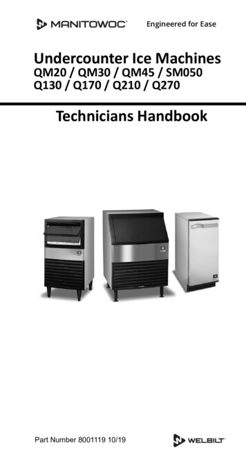
UnderCounter Ice MachinesQM45 ModelsInstallation, Operation and Maintenance ManualThis manual is updated as new information and models are released. Visit our website for the latest manual.Part Number: 040001360 6/14
Table of ContentsSection 1General InformationModel Numbers . . . . . . . . . . . . . . . . . . . . . . . . . . . . . . . . . . . . . . . . . . . . . . . . . . . . .Accessories . . . . . . . . . . . . . . . . . . . . . . . . . . . . . . . . . . . . . . . . . . . . . . . . . . . . . . .Tri-liminator Water Filter System . . . . . . . . . . . . . . . . . . . . . . . . . . . . . . . . . . . .Manitowoc Cleaner and Sanitizer . . . . . . . . . . . . . . . . . . . . . . . . . . . . . . . . . . .4444Section 2Installation InstructionsLocation of Ice Machine . . . . . . . . . . . . . . . . . . . . . . . . . . . . . . . . . . . . . . . . . . . . . .Ice Machine Heat of Rejection . . . . . . . . . . . . . . . . . . . . . . . . . . . . . . . . . . . . . . . . .Leveling the Ice Machine . . . . . . . . . . . . . . . . . . . . . . . . . . . . . . . . . . . . . . . . . . . . .Electrical Service . . . . . . . . . . . . . . . . . . . . . . . . . . . . . . . . . . . . . . . . . . . . . . . . . . .Voltage . . . . . . . . . . . . . . . . . . . . . . . . . . . . . . . . . . . . . . . . . . . . . . . . . . . . . . .Fuse/Circuit Breaker . . . . . . . . . . . . . . . . . . . . . . . . . . . . . . . . . . . . . . . . . . . . .Electrical Rating . . . . . . . . . . . . . . . . . . . . . . . . . . . . . . . . . . . . . . . . . . . . . . . . .Water Service/Drains . . . . . . . . . . . . . . . . . . . . . . . . . . . . . . . . . . . . . . . . . . . . . . . .Water Supply . . . . . . . . . . . . . . . . . . . . . . . . . . . . . . . . . . . . . . . . . . . . . . . . . . .Drain Connections . . . . . . . . . . . . . . . . . . . . . . . . . . . . . . . . . . . . . . . . . . . . . . .Water Supply and Drain Line Sizing/Connections . . . . . . . . . . . . . . . . . . . . . . .Installation Checklist . . . . . . . . . . . . . . . . . . . . . . . . . . . . . . . . . . . . . . . . . . . . . . . .Before Starting the Ice Machine . . . . . . . . . . . . . . . . . . . . . . . . . . . . . . . . . . . . . . .Ice Machine Inspection . . . . . . . . . . . . . . . . . . . . . . . . . . . . . . . . . . . . . . . . . . . . . .55566666667888Ice Making Sequence of Operation . . . . . . . . . . . . . . . . . . . . . . . . . . . . . . . . . . . . .Initial Start-up Or Start-up After Automatic Shut-off . . . . . . . . . . . . . . . . . . . . . .Freeze Sequence . . . . . . . . . . . . . . . . . . . . . . . . . . . . . . . . . . . . . . . . . . . . . . .Harvest Sequence . . . . . . . . . . . . . . . . . . . . . . . . . . . . . . . . . . . . . . . . . . . . . . .Automatic Shut-off . . . . . . . . . . . . . . . . . . . . . . . . . . . . . . . . . . . . . . . . . . . . . . .Operational Checks . . . . . . . . . . . . . . . . . . . . . . . . . . . . . . . . . . . . . . . . . . . . . . . . .General . . . . . . . . . . . . . . . . . . . . . . . . . . . . . . . . . . . . . . . . . . . . . . . . . . . . . . .Siphon System . . . . . . . . . . . . . . . . . . . . . . . . . . . . . . . . . . . . . . . . . . . . . . . . .Water Float Valve Check . . . . . . . . . . . . . . . . . . . . . . . . . . . . . . . . . . . . . . . . . .Water Level Check . . . . . . . . . . . . . . . . . . . . . . . . . . . . . . . . . . . . . . . . . . . . . .Ice Bridge Thickness Check . . . . . . . . . . . . . . . . . . . . . . . . . . . . . . . . . . . . . . .99999101010101111Section 3Operation2Part Number 040001360 6/14
Table of Contents (continued)Section 4MaintenanceInterior Cleaning and Sanitizing . . . . . . . . . . . . . . . . . . . . . . . . . . . . . . . . . . . . . . .General . . . . . . . . . . . . . . . . . . . . . . . . . . . . . . . . . . . . . . . . . . . . . . . . . . . . . . .Cleaning and Sanitizing Procedure . . . . . . . . . . . . . . . . . . . . . . . . . . . . . . . . . .Exterior Cleaning . . . . . . . . . . . . . . . . . . . . . . . . . . . . . . . . . . . . . . . . . . . . . . . . . . .Cleaning the Condenser . . . . . . . . . . . . . . . . . . . . . . . . . . . . . . . . . . . . . . . . . . . . .Removal from Service/Winterization . . . . . . . . . . . . . . . . . . . . . . . . . . . . . . . . . . .121212171818Checklist . . . . . . . . . . . . . . . . . . . . . . . . . . . . . . . . . . . . . . . . . . . . . . . . . . . . . . . . . .Safety Limit Feature . . . . . . . . . . . . . . . . . . . . . . . . . . . . . . . . . . . . . . . . . . . . . . . . .Commercial Ice Machine Warranty . . . . . . . . . . . . . . . . . . . . . . . . . . . . . . . . . . . .Residential Ice Machine Limited Warranty . . . . . . . . . . . . . . . . . . . . . . . . . . . . . .19202122Section 5Customer SupportPart Number 040001360 6/143
Section 1General InformationModel NumbersAccessoriesThis manual covers the following models:Contact your Manitowoc distributor for these 1230/60/1TRI-LIMINATOR WATER FILTER SYSTEMEngineered specifically for Manitowoc ice machines, TriLiminator water filters are an efficient, dependable, andaffordable method of inhibiting scale formation, filteringsediment, and removing chlorine taste and odor.MANITOWOC CLEANER AND SANITIZERManitowoc Ice Machine Cleaner and Sanitizer areavailable in convenient 16 oz. (473 ml) and 1 gal (3.78 l)bottles. These are the only cleaner and sanitizerapproved for use with Manitowoc products.Cleaner Part Number16oz94-0456-31 Gallon 94-0580-34Sanitizer Part number16oz94-0565-31 Gallon94-0581-3Part Number 040001360 6/14
Section 2Installation InstructionsLocation of Ice MachineThe location selected for the ice machine must meet thefollowing criteria. If any of these criteria are not met,select another location. The location must be indoors. The location must be free of airborne and othercontaminants. The air temperature must be at least 2 C (35 F), butmust not exceed 43 C (110 F). The location must not be near heat-generatingequipment or in direct sunlight. The location must be capable of supporting theweight of the ice machine and a full bin of ice. The location must allow enough clearance for water,drain and electrical connections in the rear of the icemachine. The location must not obstruct airflow through oraround the ice machine (condenser airflow is in andout the front). Refer to the chart below for clearancerequirements.Top/SidesBackIce Machine Heat of RejectionSeriesIce MachineQM45Heat of Rejection*Air Conditioning**Peak17502600* B.T.U./Hour** Because the heat of rejection varies during the ice makingcycle, the figure shown is an average.Ice machines, like other refrigeration equipment, rejectheat through the condenser. It is helpful to know theamount of heat rejected by the ice machine when sizingair conditioning equipment where self-contained aircooled ice machines are installed.Leveling the Ice MachineAfter moving the ice machine into the installationlocation, it must be leveled for proper operation. Followthese steps to level the ice machine:1. Check the level of the ice machine from front to backand from side to side.2. If the ice machine is not level, adjust the levelingglides on each corner of the base of the ice machineas necessary.Self-Contained Air-Cooled5" (127 mm)*5" (127 mm)*NOTE: The ice machine may be built into a cabinet.* There is no minimum clearance requirement for the top or left andright sides of the ice machine. The listed values are recommendedfor efficient operation and servicing only.! CautionThe ice machine must be protected if it will besubjected to temperatures below 32 F (0 C).Failure caused by exposure to freezingtemperatures is not covered by the warranty. See“Removal from Service/Winterization” Section 4.Part Number 040001360 6/14Leveling Glide3. Check the level of the ice machine after eachadjustment of the leveling glides.4. Repeat steps 2 and 3 until the ice machine is levelfrom front to back and from side to side.5
Installation InstructionsSection 2Electrical ServiceWater Service/DrainsWATER SUPPLY! WarningAll wiring must conform to local, state and nationalcodes.Voltage Phase230/50/1230/60/1115/60/1Local water conditions may require treatment of thewater to inhibit scale formation, filter sediment, removechlorine, and improve taste and clarity.Total Amps2.63.15.2ImportantIf you are installing a Manitowoc Tri-Liminatorwater filter system, refer to the InstallationInstructions supplied with the filter system for icemaking water inlet connections.VOLTAGEThe maximum allowable voltage variation is 10% ofthe rated voltage on the ice machine model/serialnumber plate at start-up (when the electrical load ishighest).Follow these guidelines to install water inlet lines: Connect to potable water supply only. Do not connect the ice machine to a hot watersupply. Be sure all hot water restrictors installed forother equipment are working. (Check valves on sinkfaucets, dishwashers, etc.) If water pressure exceeds the maximumrecommended pressure, obtain a water pressureregulator from your Manitowoc distributor. Install a water shut-off valve for both the ice makingand condenser water lines (if applicable). Insulate water lines to prevent condensation.! WarningThe ice machine must be grounded in accordancewith national and local electrical codes.! WarningNever use an extension cord. If an outlet is notwithin reach of the ice machine’s power cord, havea proper amperage outlet wired closer to the icemachine.ImportantThe water inlet line is connected to the watervalve. This valve is located just behind the frontpanel of the ice machine.FUSE/CIRCUIT BREAKERA separate fuse/circuit breaker must be provided foreach ice machine.NOTE: A disconnect means must be provided for fieldwiring.ELECTRICAL RATINGThe electrical rating is used to help select the wire sizeof the electrical supply. The wire size (or gauge) alsodepends on location, materials used, length of run, etc.,so it must be determined by a qualified electrician.6DRAIN CONNECTIONSFollow these guidelines when installing drain lines toprevent drain water from flowing back into the icemachine and storage bin: Drain lines must have a 2.5 cm drop per 1 meter ofrun (1.5 inch per 5 feet), and must not create traps. The floor drain must be large enough toaccommodate drainage from all drains. Insulate the bin drain line to prevent condensation.Part Number 040001360 6/14
Section 2Installation InstructionsWATER SUPPLY AND DRAIN LINE SIZING/CONNECTIONS! CautionPlumbing must conform to state and local codes.Ice MakingWater InletIce Making/BinWater DrainWaterTemperature0.6 C (33 F) Min.132.2 C (90 F) Max.2WaterPressure137.9 kPA (20 psi) Min.1551.5 kPA (80 psi) Max.2————Ice MachineFitting3/8" male hoseconnection1.59 cm (5/8") insidediameter flexible hoseTubing Size Up to IceMachine Fitting0.95 cm (3/8") minimuminside diameter1.59 cm (5/8") minimuminside diameter1 Min. Minimum2 Max. MaximumICE MAKING WATER INLETTUBING 0.95 cm (3/8") MIN.I.D.WATER SHUTOFFVALVEICE MAKING WATER/BINDRAIN 1.59 cm (5/8") MIN.I.D.Typical Water Supply and Drain Line Sizing and ConnectionsPart Number 040001360 6/147
Installation InstructionsInstallation ChecklistIs the ice machine level?Section 2Before Starting the Ice MachineAll Manitowoc ice machines are factory-operated andadjusted before shipment. Normally, new installations donot require any adjustment.Has all of the internal packing been removed?To ensure proper operation, follow the OperationalChecks. Starting the ice machine and completing theOperational Checks are the responsibilities of the owner/operator.Have all of the electrical and water connectionsbeen made?Adjustments and maintenance procedures outlined inthis manual are not covered by the warranty.Ice Machine InspectionHas the supply voltage been tested andchecked against the rating on the nameplate?Check all water fittings and lines for leaks. Also, makesure the refrigeration tubing is not rubbing or vibratingagainst other tubing, panels, etc.Is there proper clearance around the icemachine for air circulation?Do not put anything (boxes, etc.) in front of the icemachine. There must be adequate airflow through andaround the ice machine to maximize ice production andensure long component life.Has the ice machine been installed whereambient temperatures will remain in the rangeof 35 – 110 F (2 – 43 C)?Has the ice machine been installed where theincoming water temperature will remain in therange of 33 – 90 F (1 – 32 C)?! WarningPERSONAL INJURY POTENTIALDo not operate equipment that has been misused,abused, neglected, damaged, or altered/modifiedfrom that of original manufactured specifications.Are all electrical leads free from contact withrefrigeration lines and moving equipment?Has the owner/operator been instructedregarding maintenance and the use ofManitowoc Cleaner and Sanitizer?Has the owner/operator completed the warrantyregistration card?Has the ice machine and bin been sanitized?Has this manual been given to the owner/operator?8Part Number 040001360 6/14
Section 3OperationIce Making Sequence of OperationINITIAL START-UP OR START-UP AFTERAUTOMATIC SHUT-OFF1. Pressure EqualizationBefore the compressor starts the hot gas valve isenergized for 15 seconds to equalize pressures duringthe initial refrigeration system start-up.2. Refrigeration System Start-UpThe compressor starts after the 15-second pressureequalization, and remains on throughout the entireFreeze and Harvest Sequences. The hot gas valveremains on for 5 seconds during initial compressor startup and then shuts off.At the same time the compressor starts, the condenserfan motor (air-cooled models) is supplied with powerthroughout the entire Freeze and Harvest Sequences.The fan motor is wired through a fan cycle pressurecontrol, therefore it may cycle on and off. (Thecompressor and condenser fan motor are wired throughthe relay. As a result, any time the relay coil is energized,the compressor and fan motor are supplied with power.)FREEZE SEQUENCE3. PrechillThe compressor is on for 30 seconds prior to water flowto Prechill the evaporator.4. FreezeThe water pump starts after the 30-second Prechill. Aneven flow of water is directed across the evaporator andinto each cube cell, where it freezes.HARVEST SEQUENCE5. HarvestThe water pump de-energizes stopping flow over theevaporator. The rising level of water in the sump troughdiverts water out of the overflow tube, purging excessminerals from the sump trough. The hot gas valve alsoopens to divert hot refrigerant gas into the evaporator.The refrigerant gas warms the evaporator causing thecubes to slide, as a sheet, off the evaporator and into thestorage bin. The sliding sheet of cubes contacts the icedamper, opening the bin switch.The momentary opening and re-closing of the bin switchterminates the Harvest Sequence and returns the icemachine to the Freeze Sequence (steps 3 - 4).AUTOMATIC SHUT-OFF6. Automatic Shut-OffWhen the storage bin is full at the end of a HarvestSequence, the sheet of cubes fails to clear the icedamper and will hold it down. After the ice damper isheld open for 7 seconds, the ice machine shuts off. Theice machine remains off for 3 minutes before it canautomatically restart.The ice machine remains off until enough ice has beenremoved from the storage bin to allow the ice to fall clearof the damper. As the ice damper swings back to theoperating position, the bin switch re-closes and the icemachine restarts (steps 1 - 2), provided the 3-minutedelay period is complete.When sufficient ice has formed, the water flow (not theice) contacts the ice thickness probe. Afterapproximately 7 seconds of continual water contact, theHarvest Sequence is initiated. The ice machine cannotinitiate a Harvest Sequence until a 6-minute freeze timehas been surpassed.Part Number 040001360 6/149
OperationSection 3Operational ChecksGENERALWATER FLOAT VALVE CHECKYour Manitowoc ice machine was factory-operated andadjusted before shipment. Normally, a newly installed icemachine does not require any adjustment.Before water will flow into the water trough the floatvalve shut-off must be in the OPEN position.To ensure proper operation, always follow theseOperational Checks when starting the ice machine:PRESS TOOPEN for the first time after a prolonged out of service period after cleaning and sanitizingRoutine adjustments and maintenance proceduresoutlined in this manual are not covered by the warranty.PRESS TOCLOSESIPHON SYSTEMTo reduce mineral build-up and cleaning frequency, thewater in the sump trough must be purged during eachharvest cycle.When the water pump de-energizes the level in thewater trough rises above the standpipe starting a siphonaction. The siphon action stops when the water level inthe sump trough drops. When the siphon action stops,the float valve refills the water trough to the correct level.Siphon System CheckFollow steps 1 through 6 under water level check.SIPHONCAPWATERLEVELSTANDPIPEDRAIN10Part Number 040001360 6/14
Section 3OperationWATER LEVEL CHECKICE BRIDGE THICKNESS CHECKCheck the water level while the ice machine is in the icemode and the water pump is running. The correct waterlevel is 1/4" (6.3 mm) to 3/8" (9.5 mm) below the top ofthe standpipe a line in the water trough indicates thecorrect level.NOTE: During shipping and installation the ice thicknessprobe may shift, requiring further adjustment to achievethe rated energy efficiency and production. The iceweight per cycle must be within the minimum andmaximum for your ice machine series. Capture andweigh the ice from the second freeze/harvest cycle. Thetarget weight is the middle of the minimum andmaximum weight in the chart below.SIPHON CAPSeriesIce MachineQM45Ice Weight From One CycleMinimum IceMaximum IceWeightWeight1.1 lbs1.3 lbsTarget weight is the middle of the minimum and maximum weight.SET THE WATER LEVELTO THE LINE IN THEWATER TROUGHThe ice thickness probe is factory-set to maintain the icebridge thickness at 1/8" (3.2 mm).1. Inspect the bridge connecting the cubes. It shouldbe about 1/8" (3.2 mm) thick.The float valve is factory-set for the proper water level. Ifadjustments are necessary:1. Verify the ice machine is level (see page 4-6).2. Remove the siphon cap from the standpipe.3. Place the main ON/OFF/WASH toggle switch to theON position, and wait until the float valve stopsadding water.2. If adjustment is necessary, turn the ice thicknessprobe adjustment screw clockwise to increasebridge thickness, or counterclockwise to decreasebridge thickness.NOTE: Turning the adjustment 1/3 of a turn will changethe ice thickness about 1/16" (1.5 mm).ADJUSTING SCREW4. Adjust the water level to (1/4" to 3/8" [6.3 to 9.5 mm]below the standpipe) the line in the water trough.5. Loosen the two screws on the float valve bracket.6. Raise or lower the float valve assembly asnecessary, then tighten the screws.7. Move the main ON/OFF/ WASH toggle switch to theOFF position. The water level in the trough will riseabove the standpipe and run down the drain.1/8" ICE BRIDGE THICKNESS8. Replace the siphon cap on the standpipe, and verifywater level and siphon action by repeating steps 3through 5.Make sure the ice thickness probe wire and the bracketdo not restrict movement of the probe.Part Number 040001360 6/1411
Section 4MaintenanceInterior Cleaning and SanitizingGENERALClean and sanitize the ice machine every six months forefficient operation. If the ice machine requires morefrequent cleaning and sanitizing, consult a qualifiedservice company to test the water quality andrecommend appropriate water treatment.The ice machine must be taken apart for cleaning andsanitizing.! CautionUse only Manitowoc approved Ice Machine Cleaner(part number 94-0546-3) and Sanitizer (partnumber 94-0565-3). It is a violation of Federal lawto use these solutions in a manner inconsistent withtheir labeling. Read and understand all labelsprinted on bottles before use.CLEANING AND SANITIZING PROCEDURE! CautionDo not mix Ice Machine Cleaner and Sanitizersolutions together. It is a violation of Federal law touse these solutions in a manner inconsistent withtheir labeling.Step 1 Set the toggle switch to the OFF position afterice falls from the evaporator at the end of a Harvestcycle. Or, set the switch to the OFF position and allowthe ice to melt off the evaporator.! CautionNever use anything to force ice from the evaporator.Damage may result.Step 2 Remove all ice from the bin.Step 3 To start a cleaning cycle, move the toggle switchto the WASH position.Step 4 Add the proper amount of Manitowoc IceMachine Cleaner to the water trough.ModelQM45Amount of Cleaner1.5 ounces (45 ml)Step 5 Wait until the clean cycle is complete(approximately 22 minutes) then place the toggle switchin the OFF position, disconnect power and watersupplies to the ice machine.! WarningDisconnect electric power to the ice machine at theelectric switch box before proceeding.! WarningWear rubber gloves and safety goggles (and/or faceshield) when handling Ice Machine Cleaner orSanitizer.Ice machine cleaner is used to remove lime scale andmineral deposits. Ice machine sanitizer disinfects andremoves algae and slime.Step 6 Remove parts for cleaning.A. Remove Two Thumbscrews and Water PumpCover (When Used).B. Remove the Vinyl Hose Connecting theWater Pump and Water Distribution TubeC. Remove Water Pump Disconnect the water pump power cord Loosen the screws securing the pumpmounting bracket to the bulkhead Lift the pump and bracket assembly off themounting screws.12Part Number 040001360 6/14
Section 4Maintenance.Ice Thickness Probe Cleaning Mix a solution of Manitowoc ice machine cleaner andwater (2 ounces of cleaner to 16 ounces of water) ina container. Soak the ice thickness probe a minimum of 10minutes.When Used - REMOVETHUMBSCREWS ANDWATER PUMP COVERDO NOT SOAKWATER PUMP MOTOR INCLEANER OR SANITIZERSOLUTIONSClean all ice thickness probe surfaces and verify the icethickness probe cavity is clean. Rinse thoroughly withclean water, then dry completely. Incomplete rinsing anddrying of the ice thickness probe can cause prematureharvest.E. Remove the Water Distribution Tube31. LIFT UP2. SLIDE BACK3. SLIDE TO RIGHT21DISTRIBUTIONTUBETHUMBSCREWWater Pump RemovalLOCATINGPIND. Remove the Ice Thickness Probe Compress the side of the ice thickness probenear the top hinge pin and remove it from thebracket.THUMBSCREWNOTE: At this point, the ice thickness probe can easilybe cleaned. If complete removal is desired follow the icethickness probe wire to the bulkhead grommet (exitpoint) in the back wall. Pop the bulkhead grommet out ofthe back wall by inserting fingernails or a flat objectbetween the back wall and the grommet and pryingforward. Pull the bulkhead grommet and wire forwarduntil the connector is accessible, then disconnect thewire lead from the connector. Loosen the two thumbscrews, which secure thedistribution tube. Lift the right side of the distribution tube up off thelocating pin, then slide it back and to the right.! CautionDo not force this removal. Be sure the locating pin isclear of the hole before sliding the distribution tubeout.Part Number 040001360 6/1413
MaintenanceSection 4DisassemblyF. Remove the Float Valve Twist both of the inner tube ends until the tabs line upwith the keyways. Pull the inner tube ends outward. Turn the splash shield counterclockwise one or twoturns.FLOAT VALVEBRACKETINNER TUBECOMPRESSIONFITTINGSHUT-OFF VALVETABINNER TUBESPLASH SHIELDKEYWAYCAP ANDFILTER SCREENFLOAT14 Pull the float valve forward and off the mountingbracket. Disconnect the water inlet tube from the float valve atthe compression fitting. Remove the cap and filter screen for cleaning.Part Number 040001360 6/14
Section 4MaintenanceG. Remove the Water TroughH. Remove the ice damper. Apply downward pressure on the siphon tube andremove from the bottom of the water trough. Remove the upper thumbscrew. While supporting the water trough remove the twothumbscrews from beneath the water trough. Remove the water trough from the bin area.UPPERTHUMBSCREWLOWERTHUMBSCREWSREMOVESIPHON TUBE Grasp ice damper and apply pressure toward the lefthand mounting bracket. Apply pressure to the right hand mounting bracketwith thumb. Pull ice damper forward when the right hand icedamper pin disengages.InstallationPart Number 040001360 6/14 Place ice damper pin in left hand mounting bracketand apply pressure toward the left hand mountingbracket. Apply pressure to the right hand mounting bracketwith thumb. Push ice damper toward evaporator until right handdamper pin engages.15
MaintenanceSection 4I. Remove the Bin Door Grasp the rear of the bin door and pull bin doorforward approximately 5" (13 cm). Slide bin door to the rear while applying upwardpressure (The rear door pins will ride up into the trackslot and slide backward to the stop tab). While applying pressure against the bin door pulldown on the rear of each bin door track until the doorpins clear the stop tabs. Slide the rear door pins off the end and then belowthe door track. Slide bin door forward allowing theback of the door to lower into the bin. Continueforward with the bin door until the front pins bottomout in the track. Lift right side of door until the front pins clear thetrack, then remove door from bin.PRESS DOWNTO RELEASEDOORStep 7 Mix a solution of cleaner and warm water.Depending on the amount of mineral buildup, a largerquantity of solution may be required. Use the ratio in thetable below to mix enough solution to thoroughly cleanall parts.Solution TypeWaterMixed withCleaner1 gal. (4 l)16 oz (500 ml) cleanerStep 8 Use 1/2 of the cleaner/water solution to clean allcomponents. The cleaner solution will foam when itcontacts lime scale and mineral deposits; once thefoaming stops use a soft bristle brush, sponge or cloth(not a wire brush) to carefully clean the parts. Soak theparts for 5 minutes (15 – 20 minutes for heavily scaledparts). Rinse all components with clean water.Step 9 While components are soaking, use 1/2 of thecleaner/water solution to clean all foodzone surfaces ofthe ice machine and bin. Use a nylon brush or cloth tothoroughly clean the following ice machine areas:STOP TAB Evaporator plastic parts – including top, bottom andsides Bin bottom, sides and topTRACK SLOTRinse all areas thoroughly with clean water.SLIDE DOORFORWARDStep 10 Mix a solution of sanitizer and warm water.Solution TypeWaterMixed WithSanitizer6 gal. (23 l)4 oz (120 ml) sanitizerStep 11 Use 1/2 of the sanitizer/water solution tosanitize all removed components. Use a cloth or spongeto liberally apply the solution to all surfaces of theremoved parts or soak the removed parts in thesanitizer/water solution. Do not rinse parts aftersanitizing.16Part Number 040001360 6/14
Section 4MaintenanceStep 12 Use 1/2 of the sanitizer/water solution tosanitize all foodzone surfaces of the ice machine andbin. Use a cloth or sponge to liberally apply the solution.When sanitizing, pay particular attention to the followingareas: Evaporator plastic parts - including top, bottom andsidesBin bottom, sides and topDo not rinse the sanitized areas.Step 19 Use 1/2 of the sanitizer/water solution tosanitize all removed components. Use a cloth or spongeto liberally apply the solution to all surfaces of theremoved parts or soak the removed parts in thesanitizer/water solution. Do not rinse parts aftersanitizing.Step 20 Use 1/2 of the sanitizer/water solution tosanitize all foodzone surfaces of the ice machine andbin. Use a cloth or sponge to liberally apply the solution.When sanitizing, pay particular attention to the followingareas:Step 13 Replace all removed components.Step 14 Reapply power and water to the ice machineand place the toggle switch in the WASH position.Step 15 Add the proper amount of Manitowoc IceMachine Sanitizer to the water trough. Evaporator plastic parts - including top, bottom andsides Bin bottom, sides and topDo not rinse the sanitized areas.Step 21 Replace all removed components.ModelQM45Amount of Sanitizer1.5 ounces (45 ml)Step 16 Wait until the sanitize cycle is complete(approximately 22 minutes) then place the toggle switchin the OFF position, disconnect power and watersupplies to the ice machine.! WarningDisconnect electric power to the ice machine at theelectric switch box before proceeding.Step 17 Repeat step 6 to remove parts for handsanitizing.Step 22 Reapply power and water to the ice machineand place the toggle switch in the ICE position.Exterior CleaningClean the area around the ice machine as often asnecessary to maintain cleanliness and efficientoperation.Sponge any dust and dirt off the outside of the icemachine with mild soap and water. Wipe dry with aclean, soft cloth.A commercial grade stainless steel cleaner/polish canbe used as necessary.Step 18 Mix a solution of sanitizer and warm water.Solution TypeSanitizerWater6 gal. (23 l)Part Number 040001360 6/14Mixed With4 oz (120 ml) sanitizer17
MaintenanceSection 4Cleaning the Condenser! WarningDisconnect electric power to the ice machine atthe electric service switch before cleaning thecondenser.A dirty condenser restricts airflow, resulting inexcessively high operating temperatures. This reducesice production and shortens component life. Clean thecondenser at least every six months. Follow the stepsbelow.Removal from Service/WinterizationSpecial precautions must be taken if the ice machine isto be removed from service for an extended period oftime or exposed to ambient temperatures of 32 F (0 C)or below.! CautionIf water is allowed to remain in the ice machine infreezing temperatures, severe damage to somecomponents could result. Damage of this nature isnot covered by the warranty.Follow the applicable procedure below.! WarningThe condenser fins are sharp. Use care whencleaning them.1. The washable aluminum filter on self-contained icemachines is designed to catch dust, dirt, lint andgrease. T
1. Check the level of the ice machine from front to back and from side to side. 2. If the ice machine is not level, adjust the leveling glides on each corner of the base of the ice machine as necessary. Leveling Glide 3. Check the level of the ice machine after each adjustment of the leveling glides. 4. Repeat steps 2 and 3 until the ice .