Transcription
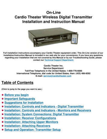
On-LineCardio Theater Wireless Digital TransmitterInstallation and Instruction ManualFull installation instructions accompany your Cardio Theater equipment order. This On-Line version of ourInstallation/Instruction Manual is included in our web site for your convenience. If you have any questionsregarding your installation that are not covered by this Manual or by our Troubleshooting Guide, pleasecontact our Technical Support Department:Cardio Theater Inc.Service DepartmentToll-Free Telephone in the United States: 1-800-776-6695International Telephone, dial code for United States, then: (425) 486-9292E-mail: service@cardiotheater.comTable of Contents(Click to jump to the page you want to see.)Before you beginImportant SafeguardsSuggestions for InstallationInstallation: Controls and Indicators - Digital TransmitterInstallation: Controls and Indicators - Monitors and ReceiversInstallation: System Connections: Digital TransmitterInstallation: Receiver ConfigurationsInstallation: Attaching Upper MonitorsInstallation: Attaching ReceiversSetup and Operation: Transmitter Setup
SpecificationsBefore You BeginPlease insure that you have all of the required equipment before disposing of anypacking materials.Equipment List:Wireless Digital TransmitterUpper Monitors,quantity as orderedAntenna,(1) for each TransmitterPower Cord,quantity (1)Plastic wire ties;(4) for each Upper MonitorReceivers,quantity as orderedCoiled Cables;(1) for each Upper MonitorPower Adapter;As orderedClick here to go back to the Index.Coax Cable;(1) for each Floor Monitor
Important SafeguardsPlease read all of these safeguards before operating the unit. Follow all warnings placed on the unit and adhere to theoperating and use instructions. Retain your manual for future reference.1. Power sources - Connect the unit to a power source onlyof the type described in the operating instructions or as markedon the appliance.2. Power cord protection - Route all power-supplycords so that they are not walked on or pinched by itemsplaced upon or againstthem.3. Grounding - Take precautions so that the grounding orpolarization means of the unit are not defeated.4. Ventilation - Position the unit so that its location doesnot interfere with ventilation. To maintain goodventilation, do not put items on or over the unit. Do notuse the unit on a cushioned surface that may block theventilation openings.5. Water and moisture - Do not locate the unit nearwater.6. Temperature - The unit may not function properly ifused at extreme temperatures. The ideal temperature is41oF (5oC) to 87oF (30oC)7. Heat - The unit should be located away from heat sourcessuch as radiators, heat registers, stoves, etc8. Electric shock - Care should be taken so that objectsdo not fall and liquid is not spilled on the enclosure. If ametal object, such as a hairpin or a needle, comes incontact with the inside of this unit, a dangerous electricshock may result.
9. Enclosure removal - Never open the enclosure. If theinternal parts are accidentally touched, a serious shock mayoccur.10. Cleaning - Do not use solvents such as alcohol;paint thinner, etc. to clean the unit. Use a clean dry cloth.11. Abnormal smell - If an abnormal smell is detected,immediately turn the power OFF and disconnect the powercord. Contact your dealer or service center.12. Stands - Any component should be moved withcare. Quick or excessive force could cause the stand tooverturn.13. Nonuse periods - The power cord should bedisconnected when left unused for a long period of time.14. Damage requiring service - The unit should beserviced by a qualified technician when:A. The power supply cord or the plug has been damaged;B. Objects have fallen, or liquid has been spilled into theunit;C. The unit has been exposed to rain;D. The unit does not appear to operate normally orexhibits a marked change in performance; orE. The unit has been dropped, or the enclosure damaged.15. Servicing - The user should not attempt to service theunit beyond that described in this manual. All other servicingshould be referred to a qualified technician.Safety PrecautionsWARNING: To prevent fire or electric shock, do not expose this applianceto rain or moisture.Caution: If you see this symbol, beaware of its meaning: To reduce therisk of electric shock, do not removethe cover or back of the unit. Nouser-serviceable parts are inside.Refer servicing to a qualifiedtechnician.
This symbol is intended to alert theuser to the presence of uninsulated"dangerous voltage" within theproduct's enclosure that may be ofsufficient magnitude to constitute arisk of electric shock to persons.This symbol is intended to alert theuser to the presence of importantoperating and maintenanceinstructions in the literatureaccompanying the unit.Click here to go back to the Index.Suggestions for InstallationGeneral Suggestions Group the audio components in a single location to minimize cabling. Always place the Transmitter directly on topof amp when stacking with the other audio components. If the audio components are stacked in a stereo cabinet, insure that there is adequate ventilation. The CardioTheater Amplifier and Digital Transmitter each require a minimum one inch (1") clearance on both sides forventilation.Transmitter: Place the Digital Transmitter in a well ventilated area with the front and back easily accessible. Place the transmitter as high as possible to obtain the best possible transmission range. Make sure the antenna on back of transmitter is in the vertical position.Upper Monitors: When mounting Upper Monitors to equipment, take care not to interfere with the normal operation of theequipment. Likewise, the power connections and the coiled cable connecting the Receiver box to the Upper Monitor should notinterfere with normal operation of the cardiovascular equipment.
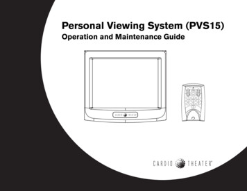
If mounting the Upper Monitor to a control panel, avoid covering controls or indicators.Receivers: The Receivers should be mounted as high as possible on the cardiovascular equipment. Mount the Receivers so that the antenna is on top in the vertical position. Mount the Receivers securely so that vibration from normal equipment operation does not cause the receiver tomove.Click here to go back to the Index.Controls and IndicatorsDigital Transmitter - FrontLegend for Digital Transmitter - Front1. Channel selectFor setting desired channel to be adjusted.2. Channel IndicatorIndicates current channel.3. Frequency IndicatorIndicates frequency assignment.4. Frequency Select
For setting the frequency assignment.5. Power-on IndicatorLights when main power switch is on.Digital Transmitter - BackLegend for Transmitter - Back1. Power Input ConnectorThe power input connector brings 110 Volts 60 Hz AC into the system.2. Main Line FuseMain system fuse for the Transmitter, 2 Amp 250 Volt Slow-Blow.3. Main Power SwitchSwitches power for the Transmitter4. Antenna ConnectorConnector for Transmitter antenna.5. Digital Input ConnectorConnector for coax cable.Click here to go back to the Index.
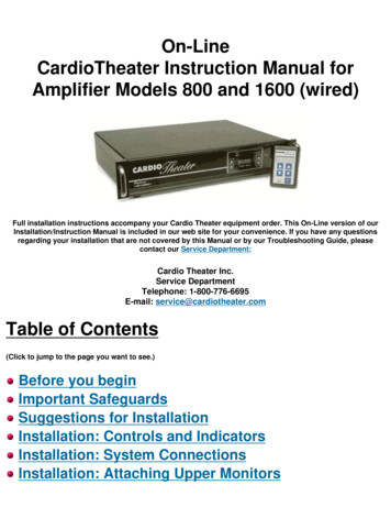
Upper MonitorLegend for Upper Monitor1. Channel DisplayIndicates current channel selected2. Channel SelectTo select the desired listening channel3. Volume AdjustTo select the desired listening volume.4. MuteAudio mute.5. Headphone JackStandard 3.5 mm headphone jack.
ReceiverLegend for Receiver1. AntennaReceives signal from Digital Transmitter.2. Power ConnectorConnector for Power.3. Monitor Box ConnectorConnector for Coiled Cable to Upper Monitor.Click here to go back to the Index.System ConnectionsNOTE:
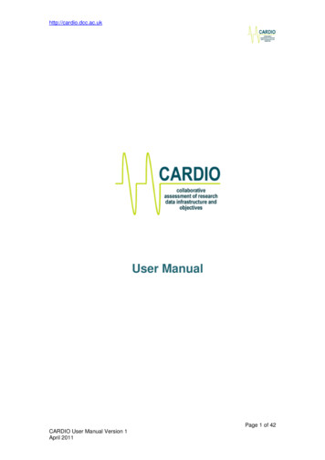
** The Cardio Theater Digital Transmitter works together with the Cardio Theater Main Amplifier. The Cardio TheaterMain Amplifier is shipped separately and is supplied with its own Installation Manual.** Before continuing with this Installation of the Digital Transmitter and Receivers, please refer to the Cardio TheaterMain Amplifier Instruction Manual pages 9 - 12. Make all connections and adjustments to the Main Amplifier beforeproceeding with this installation.Digital TransmitterNOTE: MAKE ALL CONNECTIONS TO DIGITAL TRANSMITTER AND RECEIVERSWITH THE POWER OFF. Step 1 Step 2AorStep 2B Connect the Antenna to the Antenna Connector as shownin Step 1 of diagram above.If there is no unused output connection on the CardioTheater Main Amplifier, install the eight inch (8")Coax withT Connector as shown in Step 2A; OR:If there is an unused output connection on the CardioTheater Main Amplifier, install the eight inch (8") Coax tothe digital input on the Wireless Transmitter as shownabove in Step 2B.
Step 3Use the power cord supplied to connect the DigitalTransmitter to a 120 volt AC outlet.Click here to go back to the Index.Receiver ConfigurationsThere are two (2) configurations for attaching the receivers.Contact the manufacturer of the cardiovascular equipment to determine if the unit is Cardio Theater ready, orcall the Cardio Theater Service Center (1-800-776-6695) for assistance.Receiver with poweradapter and UpperMonitor Box: Forcardiovascular equipmentthat is not Cardio Theaterready, power must besupplied via a poweradapter connected to a110 volt outlet. An UpperMonitor Box is thenattached to the receiver.Receiver powered bymachine with UpperMonitor Box:Forcardiovascular equipmentthat IS Cardio Theaterready, power will besupplied via a connectoron the cardiovascularequipment. An UpperMonitor Box is thenattached to the receiver.Click here to go back to the Index.
Attaching Upper MonitorsThe Upper Monitor can be installed on any piece of equipment.For equipment with round handles or railing, UpperMonitors are supplied with a build-in mounting block.Align the Upper Monitor on the handle or rail as desired.Use two of the supplied Plastic Wire Ties to attach theUpper Monitor to the handle or rail.Pull wire ties firmly to secure.This method is the preferred method of attaching the UpperMonitor to minimize interference with control panels anddisplays.For equipment with flat control panels but no handrails, SuperLock (a form of super strong Velcro) maybe used.Determine the best mounting position.Clean the mounting surface thoroughly.Remove the protective cover from the adhesive strip.Position the Upper Monitor and press firmly for theadhesive to grip.CAUTION: When attaching to a control panel, care shouldbe taken to avoid blocking access to controls orillustrations.Click here to go back to the Index.Attaching ReceiversThe Receivers can be installed on any piece of equipment.IMPORTANT NOTE: Make sure the Receivers are mounted as high as possible in the vertical upright positionas much as physically possible, with the antenna on top.
For equipment withround handles or railing,the Receivers aresupplied with a build-inmounting block.Align the Receiver onthe handle or rail as shown.Use two of the suppliedPlastic Wire Ties to attachthe Receiver to the handleor rail.Pull wire ties firmly tosecure.For equipment that isCardio Theater Ready,the receiver is mountedeither(1) to the back of thepanel using the screwholes, or(2) attached to thehandle or rail.For equipment with flatvertical rails, align theReceiver on the rail asdesired. Insert two PlasticWire Ties through the twolarger holes in each of theL brackets. pull wire tiesfirmly to secure.For equipment that isCardio Theater Ready with
mounting holes providedby the equipmentmanufacturer on the backof the panel, align theReceiver to the equipmentand use either two (2) orfour (4) screws to attachthe Receiver.Click here to go back to the Index.Transmitter SetupFrequency SetupFor most applications no adjustments will be necessary. If, however, one or more channels have interference or alimited range, the transmit frequencies can be adjusted as follows:
Step1Select thechannel tobe adjustedusing thechannelselectbuttons.Step2Change theselectedchannel'stransmitfrequencyusing thefrequencyselectbuttons.NOTE: TheTransmitterwillautomaticallyselect thenextavailablefrequency.Click here to go back to the Index.SpecificationsDigital TransmitterTransmission Frequency RangeFrequency RangeTransmission Power905 MHz to 924.2 MHz16 channels adjustable from 905 MHz to 924 MHz95 dbmv max.
Power Consumption610 Watt Max.DimensionsWidth: 19"/ 483 mmHeight: 3.87" / 98 mmDepth: 14.75" / 375 mm9 lbsWeightUpper MonitorOutput Level / Load ImpedanceDimensionsWeight550mV / 32 OhmWidth: 2.55" / 64.8 mmHeight: 3.93" / 99.8 mmDepth: 0.97" / 24.6 mm3 oz. / 83 gReceiverDimensionsWeightWidth: 3.27" / 83.1 mmHeight: 4.50" / 114.3 mmDepth: 1.13" / 28.7 mm8.2 oz / 233 gRegulatory InformationFCC Compliance and Advisory StatementThis device complies with Part 15 of the FCC Rules. Operation is subject to the following two conditions: 1)this device may not cause harmful interference, and 2) this device must accept any interference received,including interference that may cause undesired operation.This equipment has been tested and found to comply with the limits for a Class B digital device, pursuant toPart 15 of the FCC Rules. These limits are designed to provide reasonable protection against harmfulinterference in a residential installation.This equipment generates, uses, and can radiate radio frequency energy and, if not installed or used inaccordance with the instructions, may cause harmful interference to radio communications. However, there is
no guarantee that interference will not occur in a particular installation.If this equipment does cause harmful interference to radio or television reception, which can be determinedby turning the equipment off and on, the user is encouraged to try to correct the interference by one or moreof the following measures: 1) reorient or relocate the receiving antenna- 2) increase the separation betweenthe equipment and the receiver; 3) connect the equipment to an outlet on a circuit different from that to whichthe receiver is connected; 4) consult the dealer or an experienced radio/TV technician for additionalsuggestions.Any changes or modifications not expressly approved by the party responsible for compliance could void theuser's authority to operate the equipment. Where shielded interface cables have been provided with theproduct or specified additional components or accessories elsewhere defined to be used with the installationof the product, they must be used in order to ensure compliance with FCC regulations.Note: Cardio Theater follows a policy of continuous advancements in development. For this reason, specificationsmay be changed without notice. For questions regarding any specifications, please call the Service Center at (800)776-6695 [United States toll free number].Click here to go back to the Index.Click here to go back to the TOP of this document.
Headphone Jack Standard 3.5 mm headphone jack. Receiver Legend for Receiver 1. Antenna Receives signal from Digital Transmitter. 2. Power Connector . call the Cardio Theater Service Center (1-800-776-6695) for assistance. Receiver with power adapter and Upper Monitor Box: For cardiovascular equipment