Transcription
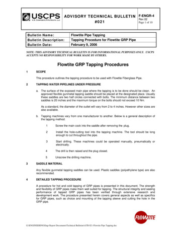
Optical Fiber Tapping: Methods and PrecautionsM. Zafar Iqbal, Habib Fathallah, Nezih BelhadjAbstract-Optical fiber communication is not as secure as generallyperceived. There are a number of known methods of extracting orinjecting information into a fiber link, while avoiding detection. Fewincidents have been reported as a successfully tapped fiber is difficultto detect. In this paper we highlight a number of known fiber tappingexplain the prototype design, hardware and software. Wealso discuss possible tapping scenarios in real environmentshighlighting the resources required to achieve it. Finally wepropose some solutions to protect optical fiber links againsttapping.methods. We report simulation of optical characteristics of a fiberbeing tapped by 'bend' method and proof of concept with iosinwhichexisting technologies. Some measures to prevent fiber tapping or tonullify the significance of information tapped from fiber were alsodiscussed.Index Terms- Optical Fiber Tapping, Layer 2 EncryptionEavesdropping, Bend tapping.I.INTRODUCTIONto the common perception, optical fiber is notC inherently secure from tapping or eavesdropping. TheONTRARYII.aresourceful eavesdropper can compromise security of a fiber link withenormous amount of mission critical and sensitiveinformation carried over fiber these days is exposed to anydetermined and resourceful eavesdropper.Fiber tapping is a process by which the security of opticalfiber is compromised by either extracting or injectinginformation (as light). Basically fiber tapping can beintrusive and non-intrusive. The former requires the fiber tobe cut and reconnected into the tapping mechanism whilethe later achieves tapping without cutting the fiber orcausing any service disruption. Non-intrusive technique isthe focus of this work.Only a few incidents of fiber tapping could be reported asit is very difficult to detect a tapped fiber while the tappingprocess itself is quite simple. Major reported incidents oftapping include the following:2000, three main trunk lines of Deutsche Telekom werebreached at Frankfurt Airport in Germany [1].FIBER TAPPING METHODSA. Fiber BendingIn this method cable is stripped down to the fiber forbending. This method exploits the principle of propagationof light through an optical fiber better described as the totalinternal reflection. To achieve this, angle of incidence oflight on the core cladding interface should be greater thanthe Critical Angle for total internal reflection. Otherwisesome light will radiate out of the fiber through its cladding.The critical angle is a function of the refractive indices ofthe core and cladding, and represented by the followingequation:Be Cos-1 (J.1daddingl J.1coreJ(prOVided flcl fie)Where,Be isthe critical Angle, flel is refractive index of Cladding, fieis refractive Index of CladdingIn fiber bending techniques the fiber is bent such that theangle of incidence becomes less than the critical angle andthe light radiates. Apparently there are further two types offiber bending:1) Micro BendingApplication of external force results in sharp butmicroscopic curvatures resulting in axial displacements of afew microns and spatial wavelength displacements of a fewmillimeters (Figure 1). The light thus radiated is used fortapping.External Force2003, an illegal eavesdropping device was discoveredhooked into Verizon's optical network [1].2005, USS Jimmy Carter, submarine specificallyretrofitted to conduct tapping into undersea cables [2],[3].In the following sections we present a brief overview ofintrusive and nonintrusive tapping techniques [4]. Then wepresent a numerical simulation of signal loss due to fiberbending followed by a report on physical demonstration oftapping on a prototype developed in our lab. Here we alsoThis paper is based on work that was supported by the Royal Saudi Airforce of Kingdom of Saudi Arabia.M. Zafar Iqbal is working in Prince Sultan Advance TechnologiesResearch Institute (ziqbal@ksu.edu.sa)Habiab Fathallah is an Associate Professor at King Saud University(hfathallah@ksu.edi.sa)Nezih Belhadj is a postdoctoral researcher at Laval -5/11/ 26.00 2011-,,,,-'IMPEREFEcnON. .". .". .,.,-.Figure 1 Micro Bending2) Macro Bending:There is a minimum tolerable bend radius associated witheach fiber type. A lesser bend radius will result in radiationof Light (figure 2). This property can be used to extract lightfrom fiber for eaves dropping. Normally, single mode fiberswill not tolerate a minimum bend radius of less than 6.5 to7.5 cm except some specially developed types. While aIEEE164
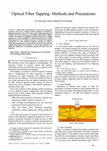
multimode fiber can tolerate a bend radius as less as 3.8cm.B. Simulation Data:For the SMF-28 fiber, the core radius and refractive indexare respectively:rc 4.15 11m and nc 1.4493Where in the cladding, they are respectively:rei 62.25 11m and ncl I.444.The refractive index of the air is 1.The curvature radius p is along the x axis, the mode ispolarized along the y axis and the propagation is along zaxis as shown in Figure 3-Figure 2. Macro BendingB. Optical SplittingThe target fiber is inserted into a splitter to tap a part ofthe optical signal. But this method is intrusive as it involvescutting the fiber that raises alarms. However, an undetectedtap of this type can work for years.C. Evanescent CouplingThis involves capturing signal from the target fiber intothe receiver fiber by polishing cladding of both to the edgeof respective core and placing them together. This allowssome signals to leak into the receiving fiber. However, thismethod is very difficult to implement under the fieldconditions.D.V Groove Figure 3C. Power Loss Computation:CutA V-groove is a cut in the cladding of the fiber close to itscore such that the angle between the light propagating in thefiber and the face of V-groove is greater than the criticalangle. This causes total internal reflection where a fractionof the light that is travelling in the cladding and overlappingV-grove will leak out of the fiber.E. ScatteringFigure 4 represents the numerical estimated bend loss as afunction of the curvature radius for 1 meter bending fiber. Alogarithmic dependence of losses versus curvature radius isobserved. For smaller curvature radii (p 10mm), lossesexceed 40 dB/m. For more usual values of curvature radius(p 15mm) the losses are less than 1 dB/m.IV. FIBER TAPPfNG EXPERIMENTBragg Grating is etched in the core of the fiber to achievereflection of some signals out of the fiber. This is achievedby creating an overlapping and interfering rays of UV raysby UV Exciter laser.III. SIMULAnONA. Methodology:A full vectorial Maxwell solver in the frequency domainbased on a High-Order Finit Element Method and allowingthe adaptation of the stretching PML (Perfectly MatchedLayer) technique is used to precisely estimate bendinglosses in an SMF-28 optical fibre. So, Vectorial computationof the propagation constants and the electric fields of themodes in bend waveguides is achieved. The bend losses arecomputed from the imaginary part of the propagationconstant of the fundamental mode. The total losses areobtained by adding the losses of both orthogonalfundamental modes. The results obtained by this method arevery accurate and have been validated in [5]A. Steps in Fiber TappingThe entire eavesdropping operation can be achieved infollowing steps:i. Tapping optical signal from fiber.ii. Detecting the signal.iii. Detecting the Transmission Mechanism (Protocol).IV. Software processing to detect the frames/ packets andextracting desired data from it.The experiment involved transmitting a video over opticalEthernet from one computer to the other. The connectingfiber was stripped to cladding and pressed by a device called"Clip on Coupler" which basically bends the fiber inducingradiation of some light that violate principle of total internetreflection. This device directs this trapped light to aUnidirectional Ethernet media converter and eventuallyEthernet frames are processed to reconstruct a copy oforiginal video frames in a third PC. We used VLC for videostreaming and playback. Wire-Shark Protocol Analyzer tocapture packets and 'Chaosreader' to reconstruct videoclippings from the captured packets.165
4003501 .5,-------.--.---,---r--,300 .E250[!J"CLosses (dB/m)-;; 200II)'"'"0.5.3 150100q 4-- 1 5-- 1 6---1 7- 18 19 J Curvature Radius: p (mm)50081012Figure 4. Numerical estimation of bend loss as a function of curvature radiusB. ProcedureAbove mentioned hardware and software are connected asshown in figure 5. The stripped fiber strand in the directionfrom video source to destination is placed under the clampof Clip-on-Coupler. The clamp is pressed resulting in somelight feeding and exciting the unidirectional media converterwhich reads Ethernet frames and feeds the third PCequipped with Wire-Shark. Wire-Shark converts Ethernetframes and provides information such as source anddestinations MAC addresses. It also processes Ethernetframe payload and obtains the IP packets from it. Theinformation obtained from the packets includes IPaddresses, signaling protocol messages and payload bits.The packets thus captured are saved in "pcap" (packetcapture) format file. This file is then processed by softwarecalled "chaosreader" which reconstructs original files andcreates an index of reconstructed files. For our capturedvideo, we look in the index, for * .DAT file of large size.Opening this file in VLC software opens the capturedportion of the video stream.C. Possible Eavesdropping ActionsBesides Video Play back, the experimental setup describehere can be used to perform as number of eavesdroppingoperations such as Attacking IPs, password stealing,listening VoIP calls and email reconstructions using variousfree, commercial or self-developed software.V. FURTHER TAPPING SCENARIOSThe experiment reported here was performed on anEthernet network as the components especially the softwarewere easily available. However, several real-world tappingscenarios can be imagined such as:Clip OnCouplerVideo reconstructedfrom interceptedMediaConverterVideoFigure 5.Experimental setup for bend tapping166
Satellite linkDataSourceTransmission UnitSDH/SONETTransmission UnitSDH/SONETTxRxDataDestinationRxTxFigure 6 Tapping with Remote processing scenarioA. Tapping Transmission NetworkMeaningful information can be obtained fromtransmission networks such as SDH and SONET, two mostprevailing standards of optical fiber transmission over LongHaul and Metro networks. The very high speed data isdifficult to be stored and processed but high-tech SDHprotocol analyzers are available that can be used to obtainlow level tributary signals [6]. This somewhat reduces thedata rate complications. Such devices can be furtherdeveloped to obtain various types of traffics flowing throughthe network. For example it may be able to extract anEthernet stream mapped onto some VC4 container stream.Remotely Processed Tapping:There are two important motivations for remoteprocessing. (1) When tapping very-high bit-rate long haultransmission links of several Gbps, the role of storagecapacity becomes important. This is due to the fact that thecaptured packet will quickly fill the hard disk. (2) NetworkForensic experts may be too precious commodity to bedeployed in the field. It is more desirable to have them atsome remote processing location equipped with state of artresources which cannot be deployed in the field. Usingimagination, some scenarios of remote processing of datatapped from a fiber can be easily conceived. For example:J) Using Wireless Ethernet:Using Wi-Fi, tapping laptop can be in another room or ina van outside the building where the tap is placed. Theforensic expert can work in a position of relative safety withaccess to better resources.2) Using Microwave/ Satellite Link:Our experimental setup has been modified by MappingEthernet Traffic on a directional Microwave link (figure 6).The processing may be done tens or even thousands ofkilometers away if Satellite link is used.3) Signal InjectionBy using the scattering method we described earlier, it istheoretically possible to construct a device that injectssignals into a fiber using some sort of coupling technique.Sophisticated techniques can be developed to jam a fiberwithout breaking it or even injecting malicious information.VI.PROTECTION AGAINST TAPPINGThree basic categories to prevent or nullity the impact offiber tapping are considered in the following along withsome discussion on respective subcategories.A. Cable Surveillance and MonitoringJ) Monitoring Signals around the FiberManufacture the optical cables with fibers surroundingthem that carry only monitoring signals. Using this methodwill increase the cost of the cable but any attempt to bendthe fiber will cause loss of monitoring signal which cableused to trigger alarms. [7].2) Electrical Conductors:Another method consists of integrating electricalconductors into the fiber cable transmitting the information.When the cable is tampered with, the capacitance betweenthe electrical conductors is altered which can be used totrigger an alarm.3) Modes' Power MonitoringThis applies to multimode fiber in which attenuation is afunction of mode in which the light is being propagated. Atap affects certain modes resulting in all the other modesbeing affected. This leads to energy being redistributed fromconducting to non-conducting modes and the powerdistribution in the fiber core and sheath are altered. Thischange in modes' power can be exploited in the receiverside by measuring the power contained in the modes andthen decide if there is tapping or not [8].4) Optical Mean Power MeasuringFiber can be monitored by the optical mean power levelbeing detected. An alarm signal being is triggered by changefrom a given reference value. This requires, however, thatthe optical signal is coded so that it has a constant meanpower independent of its information content [8].167
5) OTDRsSince tapping involves extracting part of the optical signal,the Optical time domain reflect meters (OTDRs) can be usedto detect if there is tapping by observing the locations withinthe fiber trace (figure 7.) that show decrease in signalspower. [8]oOTDRConnectors-5co -1co1il:::Jc-1sophisticated methods. The probability of successful datainterception is a function of several parameters, includingsignal-to-noise ratio and fraction of total available systemcapacity. In [12] it is shown that increasing code complexitycan increase the signal-to-noise ratio (SNR) required for aneavesdropper to "break" the encoding by only a few dB,whereas the processing of fewer than 100 bits by aneavesdropper can reduce the SNR required to break theencoding by up to 12 dB. Time-spreadinglwavelength hopping in particular and O-CDMA in general, are found toprovide confidentiality highly dependent on system designand implementation parameters.ACKNOWLEDGMENT The authors would like to thank Prince Sultan AdvanceTechnology Research Institute for rendering its facilities tosetup and perform experimental part of this work.481015202530Distance from OTDR (km)Figure 7 Finding Tap in OTDR trace6) Pilot Tone Methods:Pilot tones travel along the fiber as the communicationsdata. They are used to detect transmission disruptions. Pilottone methods can be used to detect jamming attacks. But, ifthe carrier wavelengths of pilot tones are not attacked, thismethod is not effective in detecting jamming attacks. Pilottone method detects tapping attacks by determining whetherthe pilot tones on the tapped channel are affected or not.The pilot tones are affected if the tapping attack causessignificant degradation of the signal [8].B. High Bend Fibers:These fibers, commonly referred to as low-loss high bendradius fibers, protect the network by limiting high losses thatcan result from fiber pinching or bending, therefore, makingtwisting, pulling and other physical manipulation of the fiberless damaging. There are several different designs based onvarious manufacturing techniques [9].C. EncryptionAlthough encryption cannot prevent tapping it renders thestolen information useless by making it unintelligible for theeavesdropper. Encryption can be classified into Layer 2 andLayer 3 types.1) Layer 3 EncryptionExample of Layer 2 encryption is IP Security Protocolwhich involves encryption of IP packets. It has to beimplemented at end users thus causing processing delays. Ithas to be established at the beginning of session and overallimplementation can be complicated if large number ofnetwork elements are involved. Consider for example thedevelopment of IP Multimedia Subsystem. In the initialdevelopment, communication between different nodes andelements was unsecured. It was only later that IPsec had tobe coded into the original design as prevailing underlyingtransport technologies don't offer encryption.2) Layer 2 EncryptionThis type of encryption would free layer 3 entities fromany burden of encrypting the information they arecommunicating. One possible source of Layer 2 encryptionis Optical CDMA which is considered inherently secure [1012]. This assumption is mostly based on only consideringbrute force deciphering methods, and overlooks otherVII.CONCLUSIONFiber Tapping is a tangible threat to the interests ofnational security, financial institutions or even personalprivacy and freedoms. Once tapped, the information thusobtained can be used in many difference imaginative waysas per eavesdropper's motivations and resourcefulness. Inthis paper we proved the concept both in terms of simulationand physical experiment using 'bend tap' and alsohighlighted the possibility of a number of fiber tappingscenarios achievable using available technologies. Besidesobtaining information from the fiber some techniques can beused to insert information into it, as in case of 'Evanescentsplitting' , and achieve link-jamming or feeding wronginformation. The apparent ease of eavesdropping opticalfiber warrants precautionary measures, also introduced inthis paper.REFERENCES[I][2][3][4][5]Sandra Kay Miller, "Hacking at the Speed of Light ", SecuritySolutions Magazine, April 2006Davis, USN, RADM John P."USS Jimmy Carter (SSN-23):Expanding Future SSN Missions". Undersea Waifare, Fall 1999 Vol.2,No. IOptical Illusion by: Sandra Kay Miller Information security Issue:Nov 2006.Optical Network Security: Technical Analysis of Fiber TappingMechanisms and Methods for detection and Prevention, KeithShaneman & Dr. Stuart Gray, IEEE Military CommunicationsConference 2004.R. Jedidi and R. Pierre, High-Order Finite-Element Methods for theComputation of Bending Loss in Optical Waveguides, lLT, Vol. 25,No. 9,pp. 2618-30, SEP 2007.[6]FTB-8140 Transport Blazer - 40143Gigabit SONETISDH TestModule, EXFO[7]"Optical Fiber Design for Secure Tap Proof transmission", US PatentNo. 6801700 B2, Oct. 5,2004.[8]All Optical Networks (A ON), National Communication System, NCS[9]DrakaElite,TIB 00-7, August cations,July,2010[10] W. Ford, "Computer Communications Security", Upper Saddle River,NJ: Prentice-Hall,1994.[11] D. R. Stinson, "Cryptography", Boca Raton,FL: CRC,1995.[12] N. Ferguson and 8. Schneier,"Practical Cryptography",Indianapolis,IN: Wiley,2003.168
Fiber tapping is a process by which the security of optical fiber is compromised by either extracting or injecting information (as light). Basically fiber tapping can be intrusive and non-intrusive. The former requires the fiber to be cut and reconnected into the tapping mechanism while the later achie