Transcription
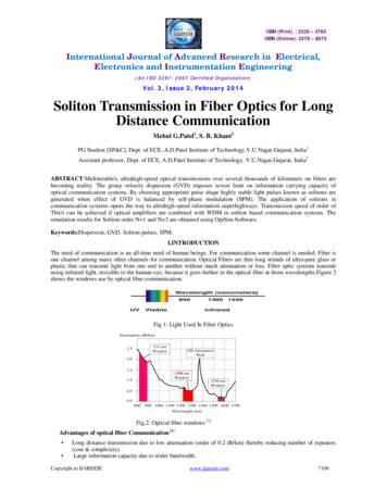
ISSN (Print) : 2320 – 3765ISSN (Online): 2278 – 8875International Journal of Advanced Research in Electrical,Electronics and Instrumentation Engineering(An ISO 3297: 2007 Certified Organization)Vol. 3, Issue 2, February 2014Soliton Transmission in Fiber Optics for LongDistance CommunicationMehul G.Patel1, S. B. Khant2PG Student [SP&C], Dept. of ECE, A.D.Patel Institute of Technology,V.U.Nagar,Gujarat, India1Assistant professor, Dept. of ECE, A.D.Patel Institute of Technology, V.U.Nagar,Gujarat, India2ABSTRACT:Multiterabit/s, ultrahigh-speed optical transmissions over several thousands of kilometers on fibers arebecoming reality. The group velocity dispersion (GVD) imposes severe limit on information carrying capacity ofoptical communication systems. By choosing appropriate pulse shape highly stable light pulses known as solitons aregenerated when effect of GVD is balanced by self-phase modulation (SPM). The application of solitons incommunication systems opens the way to ultrahigh-speed information superhighways. Transmission speed of order ofTbit/s can be achieved if optical amplifiers are combined with WDM in soliton based communication systems. Thesimulation results for Soliton order N 1 and N 3 are obtained using OptSim Software.Keywords:Dispersion, GVD, Soliton pulses, SPM.I.INTRODUCTIONThe need of communication is an all-time need of human beings. For communication some channel is needed. Fiber isone channel among many other channels for communication. Optical Fibers are thin long strands of ultra-pure glass orplastic that can transmit light from one end to another without much attenuation or loss. Fiber optic systems transmitusing infrared light, invisible to the human eye, because it goes further in the optical fiber at those wavelengths.Figure 2shows the windows use by optical fiber communication.Fig.1: Light Used In Fiber OpticsAttenuation (dB/km)850 nmWindow2.5OH AbsorptionPeak2.01.51300 nmWindow1.01550 nmWindow0.50.0800900 1000 1100 1200 1300 1400 1500 1600 1700Wavelength (nm)Fig.2: Optical fiber windows [1]Advantages of optical fiber Communication [1] Long distance transmission due to low attenuation (order of 0.2 db/km) thereby reducing number of repeaters(cost & complexity).Large information capacity due to wider bandwidth.Copyright to IJAREEIEwww.ijareeie.com7100
ISSN (Print) : 2320 – 3765ISSN (Online): 2278 – 8875International Journal of Advanced Research in Electrical,Electronics and Instrumentation Engineering(An ISO 3297: 2007 Certified Organization)Vol. 3, Issue 2, February 2014 Small size & low weight resulting in ease of installation.Immunity to electrical interference because of dielectric material.Enhanced safety since they do not have ground loops sparks, etc. However, laser light can damage eye.Increased signal security since the optical signal is well confined within the fiber.Low cost as compared to copper (as glass is made from sand. The raw material used to make of is free .)Zero resale value (so theft is less)Disadvantages of optical fiber Communication [1] OFC is delicate so has to be handled carefully.Communication is not totally in optical domain, so repeated electric -optical -electrical conversion is needed.Optical amplifiers, splitters, MUX-DEMUX are still in development stages.Dispersion PhenomenonDispersion represents a broad class of phenomena related to the fact that the velocity of the electromagnetic wavedepends on the wavelength. In telecommunication the term of dispersion is used to describe the processes which causethat the signal carried by the electromagnetic wave and propagating in an optical fiber is degraded as a result of thedispersion phenomena. This degradation occurs because the different components of radiation having differentfrequencies propagate with different velocities.Dispersion types are1.2.Mode dispersionChromatic dispersion Waveguide dispersion (optical) Material dispersion.( Group velocity, group velocity dispersion GVD) Polarization dispersionFig.3: Dispersion in optical fiber [2]The dispersion phenomenon is a problem for high bit rate and long haul optical communication systems. An easysolution of this problem is optical solitons–pulses that preserve their shape over long distances. Soliton based opticalcommunication systems can be used over distances of several thousands of kilometers with huge information carryingcapacity by using optical amplifiers. The application of solitons in communication systems opens the way to ultrahighspeed information superhighways[3]. Transmission speed of order of T bit/s can be achieved if optical amplifiers arecombined with WDM in soliton based communication systems.Copyright to IJAREEIEwww.ijareeie.com7101
ISSN (Print) : 2320 – 3765ISSN (Online): 2278 – 8875International Journal of Advanced Research in Electrical,Electronics and Instrumentation Engineering(An ISO 3297: 2007 Certified Organization)Vol. 3, Issue 2, February 2014II.SOLITON BASED TRANSMISSIONSoliton [6-10] term refers to the special kinds of waves that can propagate undistorted over long distances and remainunaffected after collisions with each other. Generally when one pulse is designated to represent ‘1’ digit, the format is called RZ (Return to Zero). On the other hand if two (or more) pulses are connected when a sequence of ‘1’ appears, the format is calledNRZ (Not Return to Zero). In addition, if the ‘1’ pulse is allowed to have two type of pulses with opposite phases; these format is calledduo-binary. Soliton format primarily uses one soliton to represent ‘1’ digit These formats are illustrated below.Fig.4: Various modulation formats for information transfer in fibers [4]Information TransmissionA digital bit stream can be generated by two distinct modulation formats i.e., non-return-to-zero (NRZ) and return-tozero (RZ). The solution of NLS equation for soliton holds only when individual pulses are well separated. This can beensured by keeping soliton width a small fraction of the bit slot. To achieve this, RZ format (Figure 5) has to be usedinstead of NRZ format when solitons are used as information bits.Fig.5: Soliton bit stream in an RZ format [3]The bit rate B and the width of the bit slot TB can be related asB 11 B 2S0 0(1)Where 2S0 TB/T0 is the normalized separation between neighbouring solitons.Copyright to IJAREEIEwww.ijareeie.com7102
ISSN (Print) : 2320 – 3765ISSN (Online): 2278 – 8875International Journal of Advanced Research in Electrical,Electronics and Instrumentation Engineering(An ISO 3297: 2007 Certified Organization)Vol. 3, Issue 2, February 2014Soliton in Optical FiberThe purpose of this example is to demonstrate the propagation of soliton pulse in optical fiber. The existence of solitonsin optical fibers is the result of a balance between the chirps induced by fiber dispersion characterized by GVD (GroupVelocity Dispersion) coefficient β2and fiber nonlinearity characterized by SPM (self-phase modulation) coefficient γ.Analytically soliton is a solution of nonlinear Schrodinger equation describing pulse propagation in optical fiber andcan be derived as[5]:A z , t Np 0 Sech t / T 0 exp j4 0 (2)Where P0- soliton peak power, T0- pulse width,Z0- soliton period, N- soliton order. Soliton period defined as 0 22 0 2(3)The optical pulse which corresponds to N 1 is called fundamental soliton. Pulses with N 1 are called higher-ordersolitons. Soliton order parameter N depends on the balance between dispersion and nonlinearity and is defined as:2 2 0 0 2(4)The layout for generation of the solitons is shown in Figure 6. It consists of pulse generator (mode-locked laser), singlemode lossless fiber, and waveform and spectrum analyzers. The fiber is assumed to be lossless to demonstrate idealsoliton propagation.III.SIMULATION AND RESULTSFigure 6 shows the layout for fundamental soliton N 1and its simplified block diagram is shown in fig.7.Thesimulation is done in OptSim software. For given n 2 2.6e-20 m2/W, Aeff 60 um2, and λ 1550 nm - γ 1.75e-3 1/m/W.The fiber length is set to one soliton period, which for given parameters is Z0 27.525 km. Initial pulse has a sech shapeand FWHM pulse width is 33 ps, corresponding to T0 18.7 ps. Pulse power for fundamental soliton is 32.7 mW and for3rd order soliton 293.4 mW. Figures 8 to 12shows soliton pulse evolution (in time and frequency domains) in fiberalong one soliton period for N 1andFigures 14 to 18 showssoliton pulse evolution (in time and frequency domains) infiber along one soliton period for N 3.By comparing the input and output figures we can say that soliton pulse shapesare exactly same after 27.525Km distances.Fig.6:Layout for soliton, N 1Copyright to IJAREEIEwww.ijareeie.com7103
ISSN (Print) : 2320 – 3765ISSN (Online): 2278 – 8875International Journal of Advanced Research in Electrical,Electronics and Instrumentation Engineering(An ISO 3297: 2007 Certified Organization)Vol. 3, Issue 2, February 2014Fig.7: Simplified Block diagram of Layout for soliton, N 1Fig.8: Input signal in time domain (N 1)Fig.9: Input signal in frequency domain (N 1)Fig.10: Output signal in time domain (N 1)Copyright to IJAREEIEwww.ijareeie.com7104
ISSN (Print) : 2320 – 3765ISSN (Online): 2278 – 8875International Journal of Advanced Research in Electrical,Electronics and Instrumentation Engineering(An ISO 3297: 2007 Certified Organization)Vol. 3, Issue 2, February 2014Fig.11: output signal in frequency domain (N 1)Fig.12: Output signal in frequency domain (without soliton parameter) (N 1)Fig.13:Layout for soliton, N 3Fig.14: Input signal in time domain (N 3)Copyright to IJAREEIEwww.ijareeie.com7105
ISSN (Print) : 2320 – 3765ISSN (Online): 2278 – 8875International Journal of Advanced Research in Electrical,Electronics and Instrumentation Engineering(An ISO 3297: 2007 Certified Organization)Vol. 3, Issue 2, February 2014Fig.15: Input signal in frequency domain (N 3)Fig.16: Output signal in time domain (N 3)Fig.17: output signal in frequency domain (N 3)Fig.18: Output signal in frequency domain (without soliton parameter) (N 3)Copyright to IJAREEIEwww.ijareeie.com7106
ISSN (Print) : 2320 – 3765ISSN (Online): 2278 – 8875International Journal of Advanced Research in Electrical,Electronics and Instrumentation Engineering(An ISO 3297: 2007 Certified Organization)Vol. 3, Issue 2, February 2014IV.CONCLUSIONSoliton based optical fiber communication systems are more suitable for long haul communication because of theirvery high information carrying capacity and repeater less transmission.Soliton pulses does not affected(by dispersion)after long distance communication. By checking the result oflayout for fundamental soliton (N 1& 3 both) we can saythat soliton pulses shape having similar shape after travelling 27.525Km distances. For N 3 source peak power isincreased as compare to N 1.V. ACKNOWLEDGEMENTSThe author would like to express thanks to Prof.S.B.khant, A.D. Patel institute of technology for his motivation, usefulinstructions, encouragement and guidance and I would also like to express thanks to Dr.V.K.Thakar (HOD) forproviding us laboratory facilities and OptSim software erd Keiser,Optical Fiber Communications, 4thedition, Tata McGraw-Hill, 2008.http://hank.uoregon.edu.R. Gangwar, S. P. Singh, and N. Singh, “Soliton based optical communication’’,Progress In Electromagnetics Research, PIER 74, 157–166,2007.Akira Hasegawa, “Soliton-based ultra-high speed optical communications’’, Vol. 57, Nos5 & 6-journal of physics Nov. & Dec. 2001.Opsim-appnotes.pdf.R. Ganapathy, K. Porsezian, A. Hasegawa, Life Fellow, IEEE, and V. N. Serkin,“Soliton Interaction Under Soliton Dispersion Management’’,IEEE journal of quantum electronics, Vol. 44, NO. 4, April 2008.David S. Ricketts, Member, IEEE, Xiaofeng Li, Student Member, IEEE, “On the Self-Generation of Electrical Soliton Pulses’’, IEEE journalof solid-state circuits, Vol. 42, NO. 8, August 2007.Yang Jing Wen and Xiang Lin Yang,Senior Member, IEEE, “Quasi-Transform-Limited Pulse Transmission in Dispersion Managed SolitonSystem’’, IEEE photonics technology letters, Vol. 11, NO. 4, April 1999.Kuppusamy Porsezian, Ramanathan Ganapathy, Akira Hasegawa, Life Fellow, IEEE, and Vladimir N. Serkin, “Nonautonomous SolitonDispersion Management’’, IEEE journal of quantum electronics, vol. 45, no. 12, December 2009.Hiroyuki Toda, Katsuyuki Mino, Yuji Kodama, Akira Hasegawa, Life Fellow, IEEE, and Peter A. Andrekson, Member, IEEE, Member,OSA,“Influence of Noise in Optical Pulse Source on Soliton Transmission’’, journal of lightwave technology, vol. 17, no. 6, June 1999.Copyright to IJAREEIEwww.ijareeie.com7107
using infrared light, invisible to the human eye, because it goes further in the optical fiber at those wavelengths.Figure 2 shows the windows use by optical fiber communication. Fig.1: Light Used In Fiber Optics OH Absorption 1.5 1.0 0.0 Wavelength (nm) Fig.2: Optical fiber windows [1] Advantages of optical fiber Communication[1]