Transcription
Fiber OpticsLab ManualInstructor’s ManualFor Classroom andHands-On Laboratory Sessions
Contacts For AssistanceYou can contact the FOA for questions and advice by phone, fax or email:The Fiber Optic Association, Inc.,Phone: 1-760-451-3655Fax: 1-760-207-2421Email: info@foa.orgWeb: www.foa.orgAvailability of plastic optical fiber (POF)The plastic optical fiber used in some of these experiments is available for sciencedistributors. It is a 1000micron (1mm) POF available from several suppliers. FOAhas samples available at no cost for teachers at schools in the US. Contact us at theemail above.This information is provided by The Fiber Optic Association, Inc. as a benefit tothose interested in teaching, designing, manufacturing, selling, installing or usingfiber optic communications systems or networks. It is intended to be used as aoverview and/or basic guidelines and in no way should be considered to be completeor comprehensive. These guidelines are strictly the opinion of the FOA and the readeris expected to use them as a basis for learning, as a reference and for creating theirown documentation, project specifications, etc. Those working with fiber optics in theclassroom, laboratory or field should follow all safety rules carefully. The FOAassumes no liability for the use of any of this material.
Fiber Optics Lab ManualPREFACEThis series of fiber optics laboratory experiments was developed by Professor EliasAwad for the FOA under a NSF grant. It is intended to introduce students in technicalhigh schools and colleges to the technology of fiber optics.No previous experience in fiber optics is required. Students are expected to read allsections of each laboratory write-up before starting with the “procedure” section ofeach experiment. In some cases, the teacher may wish to use this laboratory manualas a text. We included in each experiment enough theory, tutorial material andexamples to fulfill the needs of some programs.Teachers may wish to hold the students responsible to do the exercises provided withthe laboratory write-ups.Teachers offering a full semester of fiber optics will find it necessary to have aregular textbook for the lecture section of the course. The FOA Textbook, The FiberOptic Technicians Manual, is one choice, but at a college level, a text with moretheory, such as Fiber Optic Communications by Jim Downing or Jeff Hecht’sUnderstanding Fiber OpticsSeveral laboratory write-ups suggested that the students do the experiment with morethan one type of fiber. If this requirement is not fulfilled due to the lack of resources,the educational benefit of the experiment will not be lost.Elias A. Awademail: photons@flash.net
Lab Exercise 11- TITLE:Termination of various lengths plastic optical fibers into ametallic, 1000µm, STä fiber optic connector for plastic fiber.2- OBJECTIVE:This is an exercise. It is intended to develop your manual dexterity while teachingyou the proper installation of an ST connector on the ends of a plastic optical fiberStudents are expected to pay attention to the proper way to install the connector onthe fiber. This must be done in a way that will ensure longevity and preventpremature failure of the fiber optic link.Students will use room temperature epoxy and mechanical crimping to secure thefiber firmly into the connector. Oven cured epoxy may not be used with plastic fiber.Each student (or group of students, depending on the available budget) will prepare 9optical fibers of various lengths. Later in this manual, you will use these same fibersto perform other experiments.3- PURPOSE:We introduced this exercise to teach you the importance of installing connectors onoptical fibers. Without connectors, there will be no reliable way to align two fibers.Alignment is important to permit the transmission of an optical signal between twofibers or between a fiber and a transmit or receive instrument.Connectors are the weakest link for a signal in a fiber optic line. It is wheremaximum power losses may be found. You will learn that it is worth your while tounderstand and practice proper connector installation to avoid unnecessary servicecalls.Unnecessary service calls may annoy an engineer and will eat away at the profitmargin of a contractor who is responsible for the performance of an installation.4- TUTORIAL:x1
Typically, optical fiber is made of thin and solid strands of glass. In this case, we areusing plastic optical fiber with 1000µm diameter. The hole in the ST connector isalso 1000µm in diameter.Plastic optical fiber is not popular in long distance nor is it popular in high frequencyapplications. In long distance applications, it exhibits unacceptable losses, this iscalled attenuation. In high frequency applications, it exhibits greater pulsedistortion,this is called modal distortion. At this writing, a type of plastic optical fiber called“graded index plastic optical fiber” is underdevelopment. It promises to performsatisfactorily at substantially higher frequencies but over a distance of only 100meters or less. So as you can see, while it may be useable at higher frequencies, itsapplication will continue to be limited to a short distance. i.e.: from the street to thehome.Not only its higher losses, but also its large core diameter contribute to the poorperformance of plastic optical fiber. In a large core fibers, a large number of modesis transmitted inside the core. Each of these modes will travel a different optical path.These optical paths are unequal. This is what gives rise to modal distortion.Again, none of these optical paths is equal in length. This causes different segmentsof a single optical signal (one flash of light, one bit) to exit from the output end of thefiber at different times, thus distorting the optical pulse. This will also cause anoverlapping of adjacent optical pulses.one bit input; one flashof lightoutput with amodal distortiontwo or more bits inputoutput with a modal distortionand pulse overlapThe number of modes for each data bit in a multimode fiber is given by the “M”number of the fiber. The “M” number is given by the “V” number of the fiber:x1
M V2 / 2True only for values of V ³ 10V [(2 p a)/ l ]n12 - n22n1 and n2 are the indices of refraction of the core and cladding, respectively. a is thecore radius and l is the free space wavelength.n2claddingaguidedguidedcoren1Acceptance Coneguidedcladdingguided modeCritical Modes5- THEORY:The theory of connector making is a combination of mechanical and optical skills.Mechanically, the connector must be easy to assemble and use. It must withstandrepeated cycling and various environmental conditions. Today, connectors are beingmade from stainless or other metallic materials. Also, ceramic and compositematerials are used often. Connectors for plastic optical fiber are also found as “allplastic” or “all metallic” connectors.A large variety of connectors are found and/or being developed for glass optical fiber.Some plastic optical fiber uses a plastic “snap in” connector. Also, the standard STconnector with a modified hole diameter is used to accommodate the plastic fiber.x1Optical concerns in connector making are related to the surface preparation of theconnector which may cause pulse distortion. These are higher level concerns that do
not come into play in common typical applications. And most certainly, they do notcome into play in plastic optical fiber.Remember, this exercise is intended to develop your manual dexterity and introduceyou to the installation of connectors (in their simplest form) on an optical fiber.6- MATERIAL:Each group of 2 or 3 students needs the following:30 meter of plastic optical fiber18 AT&T ST stainless optical fiber connectors, 1000µm hole2 pads of alcohol wipesEpoxy, room temp cure or UV cure. (not oven cure)Single edge razor bladeSuitable crimp toolOVERVIEW:* Each student will prepare three or more different lengths of plastic optical fiber.* Students will work in groups of 2s or 3s.* Each fiber will have an AT&T ST style connector on each end.* When completed, each group will have nine terminated fibers of different lengths asfollow:0.1m, 0.5m, 1m, 2m, 3m, 4m, 5m, 6m and 7m7- PROCEDURE:Cut fibers longer than the desired lengths by about 5 cm. This will allowapproximately 2.5 cm of fiber to come through the front ferrule of each connector oneither side of the cable.Strip the outer jacket from either end of the fiber a distance of about 5 cm.Feed the fiber through the connector as a “ dry run” That is to see if the fiber fits andx1all of the dimensions are as you want them.*When all of the dimensions are as you want them, wipe the fiber clean with alcoholbefore you apply the epoxy (epoxy will not bond to “oily” glass or plastic).Mix the epoxy in accordance with the epoxy manufacturer’ specs. “Scoop” epoxywith the portion of the bare fiber and outside jacket that will be inside the connector.*Take special care not to let epoxy contaminate the outside of the connector.
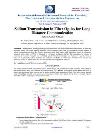
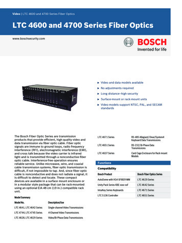
*If you get epoxy on the outside of the front ferrule, it will no longer fit into thereceptacles of the instruments.*If you get epoxy on the spring or spring housing of the connector. you will not beable to lock the connector into position.This is a detailed sketch of the ST connector and the expectedposition of the fiber in it. Below this sketch is a simplified onethat shows the two connectors at either end of a cable.KeyCore and CladdingBack FerruleFront FerruleCable outer jacketCore and CladdingThis style doesnot have aseparatecrimp sleeveThis is the AT&T ST connector.This is the STRAIGHT BODY style.Plastic optical fiber is made of a plastic core surrounded by a plastic cladding. Thetwo are housed inside an outer protective jacket. No other protective or strengthmember is present. Glass optical fiber have additional strength members built intothe cable. This makes the termination of plastic optical fiber the easiest of all fibers.x1The epoxy is used to “bond” the plastic fiber to the inside walls of the connector andthe mechanical crimping is intended to increase that bonding where the cable’s outerjacket meets the back of the connector.StainlessStainlessRubber
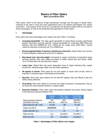
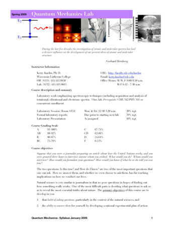
Front FerruleBack FerruleStrain ReliefFiber with outside Jacket, The AT&T STBush into connectorConnectoras far as it can go.Before polishing, cutthe fiber flush with theconnector using therazorAfter epoxy and crimping, slide thestrain relief into position. HOLDTHE CONNECTOR WHILEPUSHING THE STRAIN RELIEFFiber without outside JacketApply the epoxy, insert the fiber into the connector, crimp ASAP and let stand to curein accordance with the epoxy specifications. About 15 min. or more.Slip the strain relief while holding the connector. I said while holding the connector.Cut the fiber flush at the tip of the front ferrule.KEEP THE FIBERS CLEAN, NO FIGURE PRINTS AND NO SCRATCHES.Wipe clean with alcohol, Place the dust cover on all connectors and keep all cables ina safe place for future experiments.8- CALCULATION:In this exercise, there are no calculations to be performed.9- RESULTS:Typically, the results of a laboratory exercise gives the student the opportunity tocontrast the actual outcome to the anticipated outcome quantitatively. This does notapply in this exercise.x110- DISCUSSION:Student: Please write a short discussion. Describe, in your own words, if you had to,how you would re-write this lab. What you would change in it, and how, to make iteasier and clearer for another student to do this lab. What technical and practicaladvise would you give to someone intending to do this exercise.
11- CONCLUSION:Students: Please write a conclusion about this exercise. Contrast what was intended(as you understood it) to what was accomplished. Explain the reason(s) for anydifferences between the two. In addition, offer recommendation(s) on how to makethe outcome coincide with the objective. Do that so others doing this exercise will beable to make use of your recommendations to achieve better match between theobjective and conclusion.x1
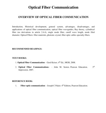
Lab Exercise 2TITLE:Polish and visually inspect terminated plastic optical fibers“from the previous laboratory exercise.”OBJECTIVE:This is an exercise. It is intended to develop your manual dexterity while teachingyou the proper procedure for polishing terminated plastic optical fiber.Students are expected to follow the instruction to the proper way to polish and protectthe fiber and the connector in which it is housed. This must be done so as tomaximize the performance of the fiber link at the connection point.Students will use 12µm Aluminum Oxide polishing film. All polishing will be drypolishing. No lubricating liquids will be used.Each student will polish one or several fibers of various lengths. This depends on thenumber of fibers and the number of students in each group.Slide as you polish. This will keep cleanpolishing film on the fiber at all timesPolish using figure 8 motion as shown. Actually, the heightand width of the figure 8 should fit into an imaginary circleas shown on the right above.KEEP IT CLEAN at all times, touch only with cleaning materialDo not transport contamination from one polishing film to thenext. Always clean your polishing fixture with alcohol wipe.x2
PURPOSE:We introduced this exercise to teach you the important points when polishing opticalfibers. Student should remember that there are some differences in polishing plasticand glass optical fibers. In this exercise. you are polishing plastic optical fiber. lookfor additional details when polishing glass optical fiber in the future.Connectors are the weakest link in a fiber optic line. You will learn that it is worthyour while to understand and practice proper connector polishing and protectiontechniques to avoid unnecessary service calls and to maximize the system’sperformance.Unnecessary service calls will eat away at the profit margin of a contractor who isresponsible for the performance of an installation. Poor system performance will eataway at the power budget of the system and may requires increased operating power.TUTORIAL:Typically, optical fiber is made of thin and solid strands of glass. In this case, we areusing plastic optical fiber with 1000µm diameter. The hole in the ST connector isalso 1000µm in diameter.Plastic optical fiber is not popular in long distance nor is it popular in high frequencyapplications. In long distance applications, it exhibits unacceptable losses, this iscalled attenuation. In high frequency applications, it exhibits greater pulsedistortion,this is called modal distortion. At this writing, a type of plastic optical fiber called“graded index plastic optical fiber” is underdevelopment by a company just outsidethe Boston, Massachusetts area and it promises to perform satisfactorily atsubstantially higher frequencies up to a distance of 100 meters. So as you can see,while it maybe useable at higher frequencies, its applications will continue to belimited to a short distance.Not only its higher losses, but also its large core diameter contribute to the poorperformance of plastic optical fiber. In a large core fibers, a large number of modesis transmitted inside the core. Each of these modes is traveling a different opticalpath.x2
None of these optical paths is equal in length. This causes different segments of theoptical signal to exit from the fiber at different times, thus distorting the optical pulse.This will also cause an overlapping of adjacent optical pulses.Optical power maybe lost from the core of a fiber due to various reasons.One of these reasons is the radiation of higher order modes into the cladding. In thecladding, these modes will attenuate rapidly and be lost for ever.In multi mode fiber (such as we are using in this exercise) higher order modes arealways present and are vulnerable to radiating out. Poorly polished connector maygive rise to and promote the development of higher order modes and perhaps theconversion of these modes into a non-guided modes, they will become lost modes.In the figure below, you can see that the difference between the guided and unguidedmodes is the angle at which the light is incident. Again, a poorly polished connectormay very well promote the conversion of guided modes into an unguided ones.LostcladdingguidedguidedcorecladdingCore - CladdingInterfaceguidedLostCritical AngleWhen theCRITICAL ANGLE is decreased,light will enter the claddingand it will be lostx2
When theCRITICAL ANGLE is increased,light will enter the coreand it will be guidedTHEORY:The theory behind polishing glass or plastic optical fiber is very simple. Use fine gritpolishing film to take out all of the surface scratches and irregularities. Leave thesurface of the fiber and connector flat, smooth and in the same plan.Under such circumstances, when two fibers are brought close together, their surfaceswill touch and make a full and smooth contact to allow the optical energy to crossfrom one to the next with only minimum loss.A large variety of connectors are found and/or being developed for glass optical fiber.Plastic optical fiber has a plastic “snap in” connector and the standard ST connectorwith an enlarged hole to accommodate the plastic fiber.Remember, this exercise is intended to develop your manual dexterity and introduceyou to the polishing and inspection technique of a plastic optical fiber.MATERIAL:Each group of 2 or 3 students needs the following:6 sheet Aluminum Oxide polishing film 12µm grit size1 hard but smooth polishing surface such as glass for each student.6 pads of alcohol wipes1 suitable polishing fixture for each student1 suitable inspection microscope with 60 or 100X magnification.OVERVIEW:x2* Each student will polish one or more connector depending on the total available* Students will work in groups of 2s or 3s.* Each end of each fiber will be polished and inspected several times.* When completed, each group will have nine terminated and polished fibers ofdifferent lengths as follow:
0.1m, 0.5m, 1m, 2m, 3m, 4m, 5m, 6m and 7m* When polishing one end of the fiber, make sure the opposite end protected so it willnot drop on the floor, drag, collect dust or scratch.PROCEDURE:You had cut the fibers longer than the desired lengths by about 5 cm. This allowedapproximately 2.5 cm of fiber to come through the front ferrule of each connector oneither side of the cable. Now, cut that piece (the 2.5 cm) flush with the surface of theconnector using a razor. You may have already done that in the previous lab.It is recommended at this point to inspect the cut and unpolished fiber with themicroscope. USE ONLY ROOM LIGHT to inspect the fiber. Follow the microscopemanufacturer’s instruction. This will allow you to see what the fiber looks like priorto polishing and give you an appreciation to the importance of polishing.Place the connector through the hole in the polishing fixture, be sure the tip of thefront ferrule sticks out from the other side of the polishing fixture.The polishing fixture will secure the fiber and connector at 90 to the polishingsurface. You must ensure that the polishing fixture stays flat on the polishing surface.Start polishing by making figure 8 motion on the polishing film. Note: the height ofthe figure 8 must equal its widthApply moderate pressure on the polishing film.Ensure that the tip of the connector, and thus the fiber, is in continuous contact withthe polishing film at all times.Ensure that the polishing fixture does not lift off of the polishing film when makingfigure 8.Do five or so laps of figure 8.Stop.Clean the tip of the fiber with alcohol.x2
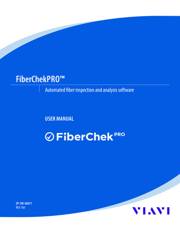
Inspect with a microscope. allow ROOM light to enter the fiber on one end whileinspecting the other end with the microscope.Repeat the process, polish, stop, clean, inspect and polish again. Monitor and observethe progress of the surface being polished.Polished plastic optical fiber will look like this. There willalways be some minor scratches. The large cross section areaof plastic fiber allows you to ignore these scratches.You may not ignore them in glass optical fiberPolished plastic optical fiber with no visible scratches.In most cases, this is hard to achieve and is not worth theeffort for plastic fiber.KEEP THE FIBERS CLEAN, NO FINGER PRINTS AND NO NEW SCRATCHES.x2Wipe clean with alcohol, Place the dust cover on all connectors and keep all cables ina safe place for future experiments.8- CALCULATION:In this exercise, there are no calculations to be performed.
9- RESULTS:Typically, the results of a laboratory exercise gives the student the opportunity tocontrast the actual outcome to the anticipated outcome quantitatively. This does notapply in this exercise.10- DISCUSSION:Student: Please write a short discussion. Describe, in your own words, how youwould re-write this lab, if you had to. What you would change in it and why. Whatadvise would you give to someone intending to do what you had just finished.11- CONCLUSION:Students: Please write a conclusion about this exercise. Contrast what was intendedto what was accomplished. Explain the reason(s) for any differences between thetwo. In addition, offer recommendation(s) on how to make the outcome coincidewith the objective. Do that so others doing this exercise will be able to make use ofyour recommendations and observations to achieve better match between theobjective and conclusion.x2
Lab Exercise 3TITLE:Power launching and the testing of optic power loss between twoplastic optical fibers in ST connectorsOBJECTIVE:This is a laboratory experiment. It is intended to develop your understanding of thetesting methodology and the testing and calculation procedure relating to opticalpower loss between two terminated plastic optical fibers.Students are reminded that there are several methods used to test connector loss. Inthis lab, we are using the “launch cable method” without mode stripping, the simplestone of all. In future labs, we may revisit this subject and use a different testingprocedure.Students will test the connector loss of only the shortest plastic fibers individually,develop understanding of the connector loss, testing procedure and calculate the lossvalue in different units.PURPOSE:Optical power loss in optical fibers is the reason we use regenerators or amplifiers inthe line. Most of the power loss usually occurs at the point of connecting two fibers.It is important that the loss at this connection point be kept to a minimum. testingconnector loss is essential to the understanding of how to keep it to a minimum.Students will learn how to set up the testing procedure correctly, how to measure theloss, how to convert that loss between different units and how the loss maybe affectedby outside variables.Once the loss and the reasons behind it are understood, the student will have learnedhow to prevent it in future terminations.TUTORIAL:1- THE UNITS OF MEASUREMENTS: In optical fiber, we use the milliWatt scalex3to measure the transmitted optical power. At the receiver, we may find ourselves
having to use the microWatt scale to evaluate the received optical power. The reasonfor selecting these units is very simple. They are just the right “size” for thetechnology today. We need not have one nor several Watts of power to get today’soptical communication systems to perform.Another unit of measure is the deciBel, also known as dB. The dB is used to measurethe relative change of power between two points in a link.10 Log10p2P1in wattsin Watts is given the unitof deciBel, dB, which mayhave a positive or a negative valueHere, students are reminded that half the power is lost for every 3dB drop.Also, you are reminded that in the definition above, its value will be if P2 P1and - if P2 P1P1any ----------------Since the typical optic power used in fiber optic communication systems is in the mWrange, we need to modify the dB unit above only to inform the reader that we areusing the mW and not any other range. If you fix the value of p1 to 1 mW, theequation above will now be written as follows and the units will be referred to asdBm10 Log10p2of any value1mW is given the unitof deciBelm or dBmThis is not a millideciBel, it is a deciBel referenced to 1 mW.Here, students are also reminded that half the power is lost for every 3dB drop. Thatis, if the power drops from 1 mW to a 0.5 mW, we say the drop is 3dB and that putsus at the -3dBm point. And if the power drops by a half again, we say the total dropis 6dB and that puts us at the -6dBm point or 0.25 milliWatt.x3
1mWany systemP2EXAMPLE: What would be the dBm reading of a 2mW optical signalSOLUTION: using the definition we write:10 Log10p2of any value1mW is given the unitof deciBelm or dBmAnytime you fix the denominatorto 1mW, your answer is in dBmwe write:2 mW10 Log10 3.01 dBm » 3 dBm1mWAN EXAMPLE for you: How many dBm is there in 1 mWof an optical signal.Do this example and pass it in to your teacher with your labwrite-up2-THE MISALIGNMENT ISSUE: One cause for optical power loss between twofibers is the misalignment of the two fibers. Misalignment can be caused byimproper polishing which may have caused the surface of the fiber to be at an angleother than 90 with respect to its axis. This angular misalignment can also be causedby the improper alignment of the two connectors.x3
In addition to the issue of angular misalignment, we have to be concerned with axialmisalignment. These deficiencies will be induced and studied in later experiments.3- THE QUALITY OF THE SURFACE: Another possible cause for optical powerloss is the issue of surface quality and preparation. Dirt, dust, finger prints, any formof contamination, and scratches on the surface contribute to the poor power transferfrom one fiber to the next.Assuming you are testing two fibers of the same type, the same core size andparameters, one or more of the variables referenced above will be a cause for powerloss. Connector loss measurements with mismatched fibers will be studied in adifferent lab experiment.4- MODE stripping is yet another possible cause for apparent connector power loss.This is a real issue and it may mislead the technician when testing connectors for loss.Future lab experiments will take into account this variable.THEORY:x3As optical power exits from an optical fiber, it exits at an angle described by Snell’slaw for ray optics. Provided the fibers are fully aligned and the surfaces are just soperfect, maximum power will be transferred from one fiber to the next. Under suchconditions, the loss will be limited to the inherent scattering and reflection.
Under such circumstances, when two fibers are brought close together, their surfaceswill touch (most but not all connectors are designed to allow physical contactbetween the two fiber surfaces) and make a full and smooth contact to allow theoptical energy to cross from one fiber to the next with only minimum loss.When the surfaces are flat and clean, excessive loss may be due to axialmisalignment. This is represented in these two overlapping circles.xdaxTWO OVERLAPPING FIBERS WITH THE COMMON SURFACE AREA, Ac, INTHE MIDDLE.In step index fiber, which this is, the optic power loss is a function of the couplingefficiency. The coupling efficiency is the ratio of the core surface area A divided bythe common surface area AcA p a2Ac 2a2 cos-1d/2a - d Öa2 - (d2/4)x3
MATERIAL:1 set LED power source and a power meter1 set of ST adapters for the source and meter1 ST to ST cable adapterOVERVIEW:* Each group will select the shortest cable as their launch or test cable* calibrate the meter against the power at the output of the best launch cable* Each group will test the connector loss of only the shortest cable they have* All students in class will work as on group* Each end of each of the short fibers will be tested against the Standard launchcable.* NOTE: Losses in plastic fibers are inherently too high. Trying to test for connectorloss requires that you know the fiber loss and you take it into account. The effect ofthis factor will be reduced by testing only the connectors on the shortest fibers.PROCEDURE:Write your group name or number on the cable.Mark both ends of the cable as “a” and “b”STEP 0NE: Connect the source and the meter with the shortest fiber, as shown, withthe “a” end into the source. Be sure the fiber is clean and free from dirt and dust.Record the reading from the meterSourceLaunch cableaMeterx3bRemove and reinstall the cable with its “b” end into the source as shown belowSourceLaunch cableMeter
baComplete the table belowSelecting the best launch cable:table for STEP 0NEGroup nameMeter read in dBm, P1a” end intothe source“b” end intothe sourcecommentsAnalyze the readings above and select the fiber and orientation with the least loss.For example, a reading of -7dBm is better than a reading of -8dBmLets say the selected cable and orientation is that of your group. Now, the rest of theclass will make and use your cable as the launch cable as shown below.Initial reading, P1 ,from thebest fiber and best orientationSourceLaunch cableabest cable as determinedfrom STEP 0NECable under testMeterbST to ST connectorx3DO NOT DISTURB THE CONNECTION AT THE SOURCE END.STEP TWO: Insert the “cable under test” between the ST to ST connector and themeter one at a time. Try both ends of the cable one end at a time. Record yourreadings in the table below and calculate the power loss for each connector.Remember, your initial reading, P1 , is the starting power level found in STEP 0NE
Connector loss recordtable for STEP TWOGroup nameMeter read in dBm, P2“a” end intothe source“a” in source , “b” in source“b” end intoConnector lossthe sourceP1 - P 2P1 - P2KEEP THE FIBERS CLEAN, NO FIGURE PRINTS AND NO NEW SCRATCHES.Wipe clean with alcohol, Place the dust cover
30 meter of plastic optical fiber 18 AT&T ST stainless optical fiber connectors, 1000µm hole 2 pads of alcohol wipes Epoxy, room temp cure or UV cure. (not oven cure) Single edge razor blade Suitable crimp tool OVERVIEW: * Each student will prepare three or more different lengths of plastic optical fiber. * Students will work in groups of 2s .