Transcription
TECHNICAL SUPPORT MANUALSplit System Air ConditionerN4A3Safety Labeling and Signal WordsDANGER, WARNING, CAUTION, andNOTEThe signal words DANGER, WARNING,CAUTION, and NOTE are used to identify levels ofhazard seriousness. The signal word DANGER isonly used on product labels to signify an immediatehazard. The signal words WARNING, CAUTION,and NOTE will be used on product labels andthroughout this manual and other manuals that mayapply to the product.DANGER -- Immediate hazards which will result insevere personal injury or death.WARNING -- Hazards or unsafe practices whichcould result in severe personal injury or death.CAUTION -- Hazards or unsafe practices whichmay result in minor personal injury or product orproperty damage.Signal Words in ManualsThe signal word WARNING is used throughout thismanual in the following manner:!WARNINGWARNINGThe signal word CAUTION is used throughout thismanual in the following manner:!CAUTIONSignal Words on Product LabelingSignal words are used in combination with colorsand/or pictures on product labels.NOTE -- Used to highlight suggestions whichwill result in enhanced installation, reliability,or operation.TABLE OF CONTENTSModel Number Identification . . . . . . . . . . . . . . . . . . . . . 2R--410A Quick Reference Guide . . . . . . . . . . . . . . . . . . 3Wiring Diagram Connection . . . . . . . . . . . . . . . . . . . . . . 4Wiring Diagram Schematic . . . . . . . . . . . . . . . . . . . . . . 5Charging Chart . . . . . . . . . . . . . . . . . . . . . . . . . . . . . . . . . 6Tech Labels (Expanded Data) . . . . . . . . . . . . . . . . 7 -- 13Condenser Only Data . . . . . . . . . . . . . . . . . . . . . . 14 -- 17Parts List . . . . . . . . . . . . . . . . . . . . . . . . . . . . . . . . . 18 -- 19Exploded Drawings . . . . . . . . . . . . . . . . . . . . . . . . 20 -- 22Cooling Multiplying Factors . . . . . . . . . . . . . . . . . 23 -- *KB200N4A330*KC200N4A360*KC300N4A336*KB200* A for standard inlet grille,G for inlet grille with 3/8” (10mm) tight--wire spacing(hail guard)!WARNINGDEATH, PERSONAL INJURY, AND/OR PROPERTYDAMAGE HAZARDFailure to carefully read and follow this warningcould result in equipment malfunction, propertydamage, personal injury and/or death.Installation or repairs made by unqualified persons could result in equipment malfunction, property damage, personal injury and/or death.The information contained in this manual is intended for use by a qualified service technician familiar with safety procedures and equipped withthe proper tools and test instruments.Installation must conform with local buildingcodes and with the National Electrical CodeNFPA70 current edition or Canadian ElectricalCode Part 1 CSA C.22.1.421 04 5101 04 June 2012
TECHNICAL SUPPORT MANUALSplit System Air Conditioner: N4A3OUTDOOR UNIT MODEL NUMBER IDENTIFICATION GUIDE (single phase)Digit Position:12345, 6789101112Example Part Number:N4A318AKB100Product Family4 R--410AREFRIGERANTA Air ConditionerH Heat PumpTYPE3 13 SEER4 14 SEERNOMINAL EFFICIENCY18 18,000 BTUH 1--1/2 tons24 24,000 BTUH 2 tons30 30,000 BTUH 2--1/2 tons36 36,000 BTUH 3 tons42 42,000 BTUH 3--1/2 tons48 48,000 BTUH 4 tons60 60,000 BTUH 5 tonsNOMINAL CAPACITYA Standard GrilleG Coil Guard GrilleC CoastalFEATURESK 208/230--1--60VOLTAGESales CodeEngineering RevisionExtra DigitExtra DigitACCESSORIES PART NUMBER IDENTIFICATION GUIDEDigit Position:123456, 78, 910, 11Example Part Number:NASA00101CHN Non--BrandedBRANDINGA AccessoryPRODUCT GROUPS Split System (AC & HP)A OriginalB 2nd Generation0 Generic or Not Applicable2 R--224 R--410AProduct Identifier NumberPackage QuantityType of Kit (Example: CH Crankcase Heater)2KIT USAGEMAJOR SERIESREFRIGERANT421 04 5101 04
TECHNICAL SUPPORT MANUALSplit System Air Conditioner: N4A3R--410A QUICK REFERENCE GUIDE R--410A refrigerant operates at 50% -- 70% higher pressures than R--22. Be sure that servicing equipment andreplacement components are designed to operate with R--410A. R--410A refrigerant cylinders are rose colored. Recovery cylinder service pressure rating must be 400 psig, DOT 4BA400 or DOT BW400. R--410A systems should be charged with liquid refrigerant. Use a commercial type metering device in themanifold hose when charging into suction line with compressor operating. Manifold sets should be 750 psig high--side and 200 psig low--side with 520 psig low--side retard. Use hoses with 750 psig service pressure rating. Leak detectors should be designed to detect HFC refrigerant. R--410A, as with other HFC refrigerants, is only compatible with POE oils. Vacuum pumps will not remove moisture from oil. Do not use liquid line filter--driers with rated working pressures less than 600 psig. Do not install a suction line filter--drier in liquid line. POE oils absorb moisture rapidly. Do not expose oil to atmosphere. POE oils may cause damage to certain plastics and roofing materials. Wrap all filter--driers and service valves with wet cloth when brazing. A liquid line filter--drier is required on every unit. Do not use with an R--22 TXV. If indoor unit is equipped with an R--22 TXV, it must be changed to an R--410A TXV. Never open system to atmosphere while it is under a vacuum. When system must be opened for service, break vacuum with dry nitrogen and replace all filter--driers. Evacuateto 500 microns before recharging. Do not vent R--410A into the atmosphere. Do not use capillary tube indoor coils. Observe all WARNINGS, CAUTIONS, NOTES, and bold text.421 04 5101 04International Comfort Products, LLCLewisburg, TN 37091 USA3
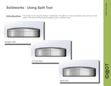
TECHNICAL SUPPORT MANUALSplit System Air Conditioner: N4A3Model Sizes: 18, 24, 30, 36, 42, 48, 60Note:1. Symbols are electrical representation only.2. Compressor and fan motor furnished with inherent thermal protection.3. To be wired in accordance with National Electric N.E.C. and local codes.4. N.E.C. class 2, 24 V circuit, min. 40 VA required, 60 VA on units installed with LLS.5. Use copper conductors only. Use conductors suitable for at least 75 C (167 F).6. Connection for typical cooling only thermostat. For other arrangements see installation instructions.7. If indoor section has a transformer with a grounded secondary, connect the grounded side to the BRN/YEL lead.8. When start capacitor and relay are installed, start thermistor (PTC) is not used.9. CH not used on all units.10. If any of the original wire, as supplied, must be replaced, use the same or equivalent wire.11. Check all electrical connections inside control box for tightness.12. Do not attempt to operate unit until service valves have been opened.13. Do not rapid cycle compressor. Compressor must be off 3 minutes to allow pressures to equalize between high and low sidebefore starting.14. Wire not present if HPS, LPS or CTD are used.4330440--101 F421 04 5101 04
TECHNICAL SUPPORT MANUALSplit System Air Conditioner: N4A3Model Sizes: 18, 24, 30, 36, 42, 48, 60330440--101 F421 04 5101 045
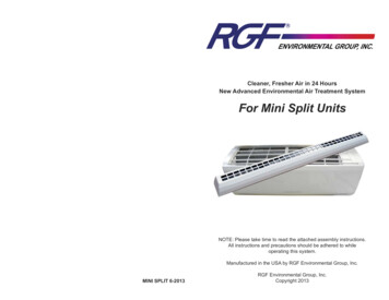
TECHNICAL SUPPORT MANUALSplit System Air Conditioner: N4A3R--410A CHARGING CHART6Measured LiquidPressure (psig) F6( C)3Rating Plate (required) Subcooling Temperature F ( C) F( C) F( C) F( C)F( 313233343637384041424344464748495051R--410A Required Liquid Line Temperature F ( 91184811647F16( 446421 04 5101 04
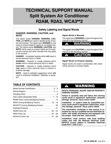
421 04 5101 04148162HI PRLO otal capacities are net (I.D. blower heat subtracted) system capacities based on 25’ line set.If additional tubing length and/or indoor unit is located above outdoor unit, a slight variation in capacity may occur.284288AMPS*1.00S/T‡5.62MBh†0.7320.88 19.19 18.02 17.91 17.89 19.84 18.31 17.18 17.19 17.19 18.84 17.37 16.28LO PR5.611451590.5316.44 16.44 17.87 16.44 15.36 15.68 15.68 16.79 15.41 14.37 14.84 14.84283287HI PR57Sensible Capacity at Indoor db HIGHER than 80 F ( MBh x S/T ) Sensible Capacity at Indoor db LOWER than 80 F ( MBh x S/T ) --(())1704878.620.571684868.500.551654858.390.53( Indoor db -- 80 ) x 835 x Indoor CFM1000( 80 -- Indoor db ) x 835 x Indoor CFM1000Chart data is for 80 F indoor dry bulb. For indoor db temperatures other than 80 F, measure Indoor db and Indoor CFM, and plug these into theformula below. Measure outdoor db and indoor wet bulb, apply these to the chart above, find MBh and S/T, and plug these into the formula below.(Note: if indoor db is the only thing changing, total capacity, MBh, stays the �1484247.771.001434227.661.001374217.550.92System amps are total of indoor and outdoor amps.1444237.780.811424227.660.771394217.550.74 15.075.497216.49S/T‡5714.6915.96 15.98 17.73 16.28 15.19 15.24 15.24 16.67 15.27 14.22 14.43 14.446214.770.7063††14.960.516716.0520.65 18.98 17.80 17.56 17.35 19.66 18.12 16.97 16.78 16.69 18.69 17.20 .39LO 1552795.400.506716.95HI Entering Indoor Temperature -- Degrees F, Wet Bulb728520.2975†† At TVA rating indoor condition (75 F db, 63 F wb), all other indoor air temperatures are at 80 F dbIf additional tubing length and/or indoor unit is located above outdoor unit, a slight variation in capacity may occur.†675600525CFMCOOLING18 Size Outdoor With ED*4X18B** Indoor CoolingOutdoor Ambient Temperature -- Degrees F, Dry BulbTECHNICAL SUPPORT MANUALSplit System Air Conditioner: N4A37
859.270.561523809.250.781423779.240.8123.04 23.04 25.12 23.21 21.821363288.140.9422.46 22.41 24.93 23.00 15 10.13 ensible Capacity at Indoor db HIGHER than 80 F ( MBh x S/T ) Sensible Capacity at Indoor db LOWER than 80 F ( MBh x S/T ) 80.791.000.59148431148431( Indoor db -- 80 ) x 835 x Indoor CFM1000( 80 -- Indoor db ) x 835 x Indoor CFM1000))17049510.28 10.28 11.441.0015649011.440.8321.10 21.10 22.46 20.71143429Chart data is for 80 F indoor dry bulb. For indoor db temperatures other than 80 F, measure Indoor db and Indoor CFM, and plug these into theformula below. Measure outdoor db and indoor wet bulb, apply these to the chart above, find MBh and S/T, and plug these into the formula below.(Note: if indoor db is the only thing changing, total capacity, MBh, stays the same.)14442916449311.130.5410.12 10.12 11.291.00‡1544331374279.961.007222.1120.55 20.55 22.33 20.541374279.960.945719.85System amps are total of indoor and outdoor amps.16843810.31 10.29 10.280.5722.08 22.08 23.86 22.02 20.651393769.081.006219.92 ((7223.4410521.49 21.49 23.69 21.83 20.451353748.920.9220.9762Entering Indoor Temperature -- Degrees F, Wet Bulb95Outdoor Ambient Temperature -- Degrees F, Dry BulbTotal capacities are net (I.D. blower heat subtracted) system capacities based on 25’ line set.If additional tubing length and/or indoor unit is located above outdoor unit, a slight variation in capacity may occur.148S/T‡162MBh†LO PR27.78 25.51LO PR288146159HI PR293287292AMPS*HI PR7.327.35S/T‡AMPS*0.770.710.52MBh†7.4827.50 25.24LO PR0.7524.01 23.92 23.93 26.38 24.39142156HI PR7.510.742862910.5423.74 23.44 23.25 26.14 � At TVA rating indoor condition (75 F db, 63 F wb), all other indoor air temperatures are at 80 F dbIf additional tubing length and/or indoor unit is located above outdoor unit, a slight variation in capacity may occur.†900800700CFMCOOLING24 Size Outdoor With ED*4X24B** Indoor 8911.441.0015148911.441.0019.39 20.03 20.0314348711.290.8119.21 19.52 19.5214148611.130.7718.9663††115TECHNICAL SUPPORT MANUALSplit System Air Conditioner: N4A3421 04 5101 04
421 04 5101 04150163HI PRLO 3914133510.21 10.20 10.190.5628.60 28.60 31.16 28.80 27.091372909.030.9927.91 27.89 30.97 28.59 70.7226.9216239114838510.72 10.97 10.951.000.5714433614433616739310.19 10.19 11.211.0015338811.190.8027.52 27.52 29.67 .921534400.8524.30143436140435Sensible Capacity at Indoor db HIGHER than 80 F ( MBh x S/T ) Sensible Capacity at Indoor db LOWER than 80 F ( MBh x S/T ) --72670.7623.9416650115249613.02 54971.001.000.600.85151439151439( Indoor db -- 80 ) x 835 x Indoor CFM1000( 80 -- Indoor db ) x 835 x Indoor CFM1000))17150315849812.29 12.29 13.51 13.491.00571.0022.580.831444931.001.0023.26 23.261444931454941.001.0014749515549715549713.48 13.49 13.490.8815049523.78 23.7815049513.24 13.24 13.2425.13 25.13 26.38 24.30 22.7414643712.04 12.04 13.27 13.256222.5712.99 12.99 12.990.7922.3563††11524.55 24.56 26.29 24.16 22.581404351.0011.79Chart data is for 80 F indoor dry bulb. For indoor db temperatures other than 80 F, measure Indoor db and Indoor CFM, and plug these into theformula below. Measure outdoor db and indoor wet bulb, apply these to the chart above, find MBh and S/T, and plug these into the formula below.(Note: if indoor db is the only thing changing, total capacity, MBh, stays the same.)1454371.0011.795723.81‡1554416223.81System amps are total of indoor and outdoor amps.16944612.32 12.30 12.290.5825.72 26.35 26.35 28.1114138310.94 10.94 10.94 12.07 12.05 12.040.7825.52 25.73 25.73 27.98 25.751383816725.50105 ((7227.7610.70 10.69 10.69 11.830.7525.2263††Entering Indoor Temperature -- Degrees F, Wet Bulb26.85 26.85 29.51 27.201343329.690.9126.196295Total capacities are net (I.D. blower heat subtracted) system capacities based on 25’ line set.If additional tubing length and/or indoor unit is located above outdoor unit, a slight variation in capacity may .3013728.3614716129032.60 30.13HI PR9.04289LO PR293298AMPS*0.75S/T‡9.04MBh†0.7332.38 29.89LO PR9.0628.12144158HI 129.5432.02MBh†63††8.82677275†† At TVA rating indoor condition (75 F db, 63 F wb), all other indoor air temperatures are at 80 F dbIf additional tubing length and/or indoor unit is located above outdoor unit, a slight variation in capacity may occur.†11251000875CFMCOOLING30 Size Outdoor With ED*4X30B** Indoor CoolingOutdoor Ambient Temperature -- Degrees F, Dry BulbTECHNICAL SUPPORT MANUALSplit System Air Conditioner: N4A39
027615841.400.55MBh†S/T‡AMPS*HI PRLO 31.2713436212.771.0030.1257Entering Indoor Temperature -- Degrees F, Wet BulbTotal capacities are net (I.D. blower heat subtracted) system capacities based on 25’ line set.If additional tubing length and/or indoor unit is located above outdoor unit, a slight variation in capacity may 57†((( Indoor db -- 80 ) x 835 x Indoor CFM1000( 80 -- Indoor db ) x 835 x Indoor CFM1000Total capacities are net (I.D. blower heat subtracted) system capacities based on 25’ line set.If additional tubing length and/or indoor unit is located above outdoor unit, a slight variation in capacity may occur.Sensible Capacity at Indoor db HIGHER than 80 F ( MBh x S/T ) Sensible Capacity at Indoor db LOWER than 80 F ( MBh x S/T ) 14.161.0028.77Chart data is for 80 F indoor dry bulb. For indoor db temperatures other than 80 F, measure Indoor db and Indoor CFM, and plug these into theformula below. Measure outdoor db and indoor wet bulb, apply these to the chart above, find MBh and S/T, and plug these into the formula below.(Note: if indoor db is the only thing changing, total capacity, MBh, stays the 0.7931.9114941814.230.7531.46System amps are total of indoor and outdoor 114.340.5534.69105 †† At TVA rating indoor condition (75 F db, 63 F wb), all other indoor air temperatures are at 80 F dbIf additional tubing length and/or indoor unit is located above outdoor unit, a slight variation in capacity may occur.†274276HI PRLO PR14811.140.7637.7214511.26AMPS*272275HI PRLO h†COOLING036 Size Outdoor With ED*4X36F** Indoor CoolingOutdoor Ambient Temperature -- Degrees F, Dry .2614247215.781.0027.29TECHNICAL SUPPORT MANUALSplit System Air Conditioner: N4A3421 04 5101 04
421 04 5101 028015549.780.56MBh†S/T‡AMPS*HI PRLO 38.1413136117.581.0036.8257Entering Indoor Temperature -- Degrees F, Wet BulbTotal capacities are net (I.D. blower heat subtracted) system capacities based on 25’ line set.If additional tubing length and/or indoor unit is located above outdoor unit, a slight variation in capacity may 257Sensible Capacity at Indoor db HIGHER than 80 F ( MBh x S/T ) Sensible Capacity at Indoor db LOWER than 80 F ( MBh x S/T ) --( Indoor db -- 80 ) x 835 x Indoor CFM1000( 80 -- Indoor db ) x 835 x Indoor 3441219.501.0035.18Chart data is for 80 F indoor dry bulb. For indoor db temperatures other than 80 F, measure Indoor db and Indoor CFM, and plug these into theformula below. Measure outdoor db and indoor wet bulb, apply these to the chart above, find MBh and S/T, and plug these into the formula below.(Note: if indoor db is the only thing changing, total capacity, MBh, stays the 9.950.5742.2415942119.626738.27System amps are total of indoor and outdoor amps.((7241.78105 †† At TVA rating indoor condition (75 F db, 63 F wb), all other indoor air temperatures are at 80 F dbIf additional tubing length and/or indoor unit is located above outdoor unit, a slight variation in capacity may occur.†277281HI PRLO PR14515.050.7745.7414215.14AMPS*275279HI PRLO h†COOLING042 Size Outdoor With ED*4X42J** Indoor CoolingOutdoor Ambient Temperature -- Degrees F, Dry .4913846721.611.0033.40TECHNICAL SUPPORT MANUALSplit System Air Conditioner: N4A311
729715755.960.52MBh†S/T‡AMPS*HI PRLO 42.7513338317.741.0041.2357Entering Indoor Temperature -- Degrees F, Wet BulbTotal capacities are net (I.D. blower heat subtracted) system capacities based on 25’ line set.If additional tubing length and/or indoor unit is located above outdoor unit, a slight variation in capacity may 557Sensible Capacity at Indoor db HIGHER than 80 F ( MBh x S/T ) Sensible Capacity at Indoor db LOWER than 80 F ( MBh x S/T ) --( Indoor db -- 80 ) x 835 x Indoor CFM1000( 80 -- Indoor db ) x 835 x Indoor 3643819.631.0039.42Chart data is for 80 F indoor dry bulb. For indoor db temperatures other than 80 F, measure Indoor db and Indoor CFM, and plug these into theformula below. Measure outdoor db and indoor wet bulb, apply these to the chart above, find MBh and S/T, and plug these into the formula below.(Note: if indoor db is the only thing changing, total capacity, MBh, stays the 0.170.5347.7316144719.826742.93System amps are total of indoor and outdoor amps.((7247.13105 †† At TVA rating indoor condition (75 F db, 63 F wb), all other indoor air temperatures are at 80 F dbIf additional tubing length and/or indoor unit is located above outdoor unit, a slight variation in capacity may occur.†294298HI PRLO PR14715.300.7151.2114415.43AMPS*292296HI PRLO h†COOLING048 Size Outdoor With ED*4X48J** Indoor CoolingOutdoor Ambient Temperature -- Degrees F, Dry .7514049921.721.0037.47TECHNICAL SUPPORT MANUALSplit System Air Conditioner: N4A3421 04 5101 04
421 04 5101 04297301150305163AMPS*HI PRLO 15134814134419.35 19.35 21.86 21.53 21.291.0060.44 60.47 67.31 61.94 58.1113529618.86 18.83 21.40 21.07 20.840.9259.33 58.75 66.67 61.31 57.4713129418.37 18.29 20.92 20.59 .000.560.7814234414234416740515339921.30 21.30 23.99 23.661.0058.18 58.19 63.93 58.8213734320.80 20.79 23.53 23.200.9456.80 56.59 63.38 ible Capacity at Indoor db HIGHER than 80 F ( MBh x S/T ) Sensible Capacity at Indoor db LOWER than 80 F ( MBh x S/T ) 4481695181555111.000.590.83149450149450( Indoor db -- 80 ) x 835 x Indoor CFM1000( 80 -- Indoor db ) x 835 x Indoor CFM1000))17251915851325.84 25.84 28.83 28.541.0053.10 53.10 56.41 51.9614444825.33 25.33 28.39 28.091.0051.77 51.77 56.07 51.58138446Chart data is for 80 F indoor dry bulb. For indoor db temperatures other than 80 F, measure Indoor db and Indoor CFM, and plug these into theformula below. Measure outdoor db and indoor wet bulb, apply these to the chart above, find MBh and S/T, and plug these into the formula below.(Note: if indoor db is the only thing changing, total capacity, MBh, stays the same.)1454491.007255.5424.82 24.81 27.93 0.7951.601404476250.27System amps are total of indoor and outdoor amps.16946023.42 23.46 23.46 26.31 25.990.8055.17 55.72 55.73 60.33 55.5214039322.97 22.95 22.95 25.86 25.540.7754.61 54.23 54.26 59.88 55.0513739224.860.7550.9263††105 ((7259.2122.50 22.45 22.42 25.39 25.070.7353.8463††Entering Indoor Temperature -- Degrees F, Wet Bulb20.31 20.25 23.05 22.730.9055.656295Total capacities are net (I.D. blower heat subtracted) system capacities based on 25’ line set.If additional tubing length and/or indoor unit is located above outdoor unit, a slight variation in capacity may occur.1390.7719.36S/T‡0.740.54MBh†19.94 19.6013760.8414716170.44 64.85LO PR296300304HI PRS/T‡AMPS*0.52MBh†0.7460.1469.71 64.15LO PR18.90133143157HI PR0.71295299303AMPS*19.47 3††18.99 18.66677275†† At TVA rating indoor condition (75 F db, 63 F wb), all other indoor air temperatures are at 80 F dbIf additional tubing length and/or indoor unit is located above outdoor unit, a slight variation in capacity may occur.†225020001750CFMCOOLING60 Size Outdoor With ED*4X60L** Indoor CoolingOutdoor Ambient Temperature -- Degrees F, Dry 85081.0015251015251028.43 28.431.0050.23 50.2314850827.93 27.931.0049.05 49.0514250627.42 27.421.0047.55TECHNICAL SUPPORT MANUALSplit System Air Conditioner: N4A313
TECHNICAL SUPPORT MANUALSplit System Air Conditioner: N4A3Data for Condenser Only (Cooling)Condenser Entering Air Temperature FSaturated SuctionTemperature .20SDT78.8050KW1.09TCG32.60SDT80.3055KW1.09TCG Gross Cooling Capacity (x
TECHNICAL SUPPORT MANUAL Split System Air Conditioner: N4A3 4 421 04 5101 04 Model Sizes: 18, 24, 30, 36, 42, 48, 60 330440--101_F 1. Symbols are electrical representation only. 2. Compressor and fan motor furnished with inherent thermal protection. 3. To be wired in accordance with National Electric N.E.C. and local codes. 4. N.E.C. class 2 .