Transcription
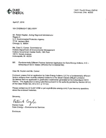
139 E. Fourth Street, EM740Cincinnati, Ohio 45202April 27, 2016VIA OVERNIGHT DELIVERYMr. Robert Kaplan, Acting Regional AdministratorRegion 5U.S. Environmental Protection Agency77 W. Jackson Blvd.Chicago, IL 60604Ms. Carol S. Comer, CommissionerIndiana Department of Environmental ManagementIndiana Government Center North, 13th Floor100 N. Senate AvenueIndianapolis, IN 46204RE:Fundamentalty Different Factors Variance Application for Duke Energy Indiana, LLC EdWardsport IGCC Station (NPDES Permit IN0002780)Dear Mr. Kaplan and Ms. Comer.Enclosed, please find an application by Duke Energy Indiana, LLC for a fundamentally differentfactors variance from recently adopted revisions to the Steam Electric EHluenl LimitationGuidelines that are applicable to gasification wastewater generated at the Edwardsport IGCCStation. This Application is being submitted pursuant to the authority granted by Section 301 (n)of the Clean Water Act, 33 U.S.C. § 1311 {n).Please contact me (513-287-2268 or pat.coyte@duke-energy.com) if you have any questionsabout the enclosed materials.Sincerely,p t Duke Energy - Environmental ServicesEnclosure
(:li,ek 011t: .,.,.,.,,bmApc!26'",,0I 0000-l lc: N Mrrlnvel« O.reoM?-2011A r1Wl016HHl*l o , I\lt. Ut INDIAl'IACftrck m n UICA1lVo r fDc,1uA o11n1DbcCMtnlS T 0fEl:fOR f,O VARIAN(' AP1'llC'IIT l0H @fP'WClittk N ttblN0 1 IIIOOl IOC'Io\p,-12&2016 DUKE -ENERGY.Ctr,or Acciounta Paye!,·ST?S8 -400 So U! Tl')' )n StreitC e, NC 2'.8285.,'Pay.,.,.Order OfSTAT OF INDIANADEPT. OF ENVIRONMENTAL MGMT.CASHIERS OFFICEI00NS A'fEAVENUElndfonapolis. IN 46204'toolTeuJTtttlCrf.lnAIMWftf0tft&41 UL.ate- Chara.nToto!P1WAmo ot 30.00so-oo 0.00s,P.oo
APPLICATION OFDUKE ENERGY INDIANA, LLCFORA FUNDAMENTALLY DIFFERENTFACTOR VARIANCEApril 27, 2016
APPLICATION OFDUKE ENERGY INDIANA, LLC FORA FUNDAMENTALL Y DIFFERENT FACTOR VARIANCETABLE OF CONTENTS1.0INTRODUCTION. . .12.0BACKGROUND . . . . . . . . . .12.1Edwardsport IGCC Station . 12.2EPA' s Rulemaking for Updated Stream Electric Power GeneratingPoint Source Category E ffluent Limitation Guidelines . . .22.2.1 Fiiral Sttem,i Electric ELGs . . . .22.2.2 Preliminary RulemakiJig Activities for Steam ElecJric ElGs .32.33.0Need for a FDF Variance for Edwardsport IGCC Station .4PLANT SPECIFIC INFORMATION . .63.1Polk Station.63.1.1 Polk's Gasijicatio11 Process .63.J.23.2Polk's Grey Water Treatment . . 8Ed vards port IGCC . . 83.2.1 Edwardsporl's Gasification Process ,wd Ge11eratio11 of Grey Water . 83.2.2 Edwardsporl's Grey Water Treatme,it System ("GWTS'') . 93.34.0Wabash ruver . . . . . . . 113.3.IWabas/r River's Gasificat/011 Process. . 1133.2Wabash's Gasijicatio11 Wastewater Treatmerit . 12SUMMARY OF EPA'S RATIONALE AND TECHNICAL BASIS FOR THEBAT ELGS FOR GASIFICATION WASTEWATER . ., .134.1Statutory Requirements for DAT Effluent Limitations . 13
5.04.2Evaporation System Is Tecbnoloc Basis for GasificationWastewater E LGs . . 134.3Gasiticatjon Wastewater Sampling at Polk and Wabash . 134.4Data Exclusions and Calculation of Limitations . 154.5Compliance Costs . 15 4.6Fina I ELG Limitations . 16DESCRIPTION OF FUNDAMENTALLY DIFFERENT FACTORS FORTHE EDWARDSPORT IGCC STATION . . . 165.1Summary of Fundamental Differences . 165.2Fundamental Differences in Fuels Used in the Gasification Process . 185.2.1 1Ji.ffere11ces in F uels Used by Polk, Wabash a11d Edwardsport IGCC. . 185.2.2 Di.ffere11ces in Fuel Coustitmmls. 185.2.3 Nature a11d Effect oftlte F111tda11umtally Differe11t Fuel Factor . 195.2.3.1 Differences in Asb Content . 195.2.3.2 Differences in Chlorine Content. .205.2.3.3 Differences in Mercury Content .215.3Fundamental Differences in Preliminary Cooling andCl ning of Syogas . . . . 215.3.1 Syngas Cooling and Clea11i11g at Polk Statio11 .225.3.2 Syngas Cooli11g a11d Clem1i11g at Edwardsport IGCC .225.3.3 Sy11gas Cooling and Cleo11i11g lit Wabaslt JGCC .235.3.4 Nature f ti,e F1mdame11tally Differe11t Factor Relati11g toSy11glls Cooli,rg and Clea11i11g .235.4Fundamental Differences io the Type and Configuration of the EvaporativeProcesses E mployed in Treatmeut of Gasification Wastewater .245.4.1Polle Station's Treatment of Gasificatio11 Waste1Mter .25ii
5.4.1.1 Type and Configuration of Polk's Evaporative Processes .255.4.1.2 Configuration of the Condeusate Outputs of Polk'sEvap orative Processes . . . 255.4.2 Edwardsport IGCC's Treatment of Gasification Wastewater . 25S.4.2.1 Differences in Type and Configuration of the EvaporativeProcesses .265.4.2.2 Differences in the Configuration of the CondensateOutputs of the Evaporative Processes at EdwardsportIGCC . . .28S.4.2.3 The ELGs for Gasification Wastewater Are NotRepresentative of the Combined Condensate Effluent ofEdwardsport IGCC's GWTS . 305.4.3Wabaslt IGCC . . . .325.4.4 Nature of tlte Fr111dame11/al/y Differences Associated withTreatme11t ofthe Gasification Wastewaters . .326.0DUKE ENERGY'S FDF VARIANCE APPLICATION MEETS STATUTORYELIGIBILITY FACTORS ., . .336.1Statutory Prerequisites to an FDF Variance . 336.2Duke Energy's Application Satisfies the Statutory Prerequisites . .336.2.1 Fundame11ta/ly Different Factors . . .336.2.2 l11formatioll Base for Application . .337.06.2.3Tlte Proposed Altemalive Limitaliotts N o Less Striltgent titanJ11stifled by the Fm1dame11tal Dijfereu ce .346.2.4Tlte Proposed Alterna.tive Limitatio,rs Will Not Res11/t i11 MarkedzyMore Adverse No11-Water Quali.ty E11viromtte11tal Impacts . .346.2.5Tlte Application is Timely . .34PROPOSAL FOR ALTERNATE BAT EFFLUENT LIMITATIONS FOREDWARDSPORT IGCC STATION'S GASIFICATION WASTEWATER .35iii
7.1Basis of Duke Energy's Requested Alternative Effluent Limitations . 357.2Proposed Alternative BAT Effluent Limitations .367.3Duke E nergy's Proposed Alternative Effluent Limitations AreConsistent with Regulatory Requirement . 377.3.JTlt e Proposed A /temative Effluent Limitations Will AssureCompfia11ce will, Water Quality-Based Efj111ent Limit.ations . . 3 77.3.2The Proposed Altemative Efjlue11t Limitations Will AssureComp/la11ce willi Section 208(e) of tlte CW.A. 398.0RESERVATION OF RIGHTS . 399.0CONCLUSION . . ,. .4010.0CERTIFICATION . ,. .41APPENDICES:Appendix 1: 2013 and 2015 Data from E dwardsport IGCC Grey Water Treatment SystemAppendix 2: Dolce Energy Technical Memorandum on EdwardsportFundamentally Different Factors Request (April 2016)I GCCAppendix 3: Coal Analyses for Edwardsport IGCC StationAppendix 4: Condensate Streams and Final Effluent Data - April 2016Edwardsport IGCC Grey Water Treatment SystemAppendix 5: Excerpts from NPDES Permit No. IN0002780 issued March 30, 2016 andAccompanying Fact Sheetiv-
APPLICATION OFDUKE ENERGY INDIANA, LLC FORA FUNDAMENTALLY DIFFERENT FACTOR1.0VARJANCEINTRODUCTIONThis is an application by Duke Energy Indiana, LLC ("Duke Energy Indiana") for afundamentally different factor variance ("FDF variance") from the Best Available TechnologyEconomically Achievable (BAT) effluent limitation guidelines contained in recently adoptedrevisions to the Effluent Limitation Guidelines for the Steam Electric Power Generating PointSource Category, 40 CFR Part 423.13, that otherwise will be applicable to the gasificationwastewater generated, treated and discharged at the Edwardsport IGCC Station, located at 15424East State Road 358, Edwardsport, Indiana. This Application is being submitted pursuant to theauthority granted by Section 301(n) of the Clean Water Act, 33 U.S.C. § 131 l(n).2.0BACKGROUND2.1Edwardsport IGCC StationDuke Energy Indiana (sometimes refened to herein as simply "Duke Energy") owns andoperates the Edwardsport IGCC Station, an integrated gasification combined cycle ("IGCC")electric generation facility, located in Edwardsport, Indiana. The Edwardsport IGCC Stationbegan commercial operation in June 2013.The gasification process utilized at the Stationincludes a recirculating grey water system associated with initial cooling and cleaning of rawsynthesis gas ("syngas") produced by the gasifiers. Slowdown from the grey water recirculatingsystem, henceforth referred to in this Application as "grey water", is subjected to extensivetreatment in the Station's grey water treatment system ("GWTS").The GWTS at Edwardsport IGCC Station is a complex. wastewater treatment system that utilizesa pr:eliminary mechanical vapor recompression concentrator followed by two crystallizers withdiffering functions. (All evaporators are based on a forced circu lation design). The combinedcondensate streams from the evaporation treatment system undergo further polishing through areverse osmosis ("RO") system. RO reject concentrate is returned to the treatment process, whileRO permeate is the treated grey water, or "effluent", from the GWTS.80D17422316
Treated grey water is primarily reused as makeup water for the recirculating cooling watersystem for the gasification process, but under certain circumstances is routed directly todownstream portions of the wastewater treatment system of the Station for discharge to the WestFork of the White River in Knox County, Indiana.1be lodiana Department of Environmental Management (IDEM) issued a renewal of NPDESPermit No. IN0002780 to Duke Energy on March 30, 2016 authorizing discharges from theEdwardsport IGCC facility. The renewal permit incorporates the BAT effluent limitations forgasification wastewater established by the recently adopted ELG revisions, including effluentlimits for arsenic, mercury, selenium, and total dissolved solids (TDS). The BAT limitations areapplied directly to the output of the GWTS at a designated internal outfall.2.2EPA's Rulcmaking for Updated Steam Electric Power Generating PointSource Category E t1uent Limitation GuidelinesWhile the Edwardsport IGCC Station was under construction, the U.S. Environmental ProtectionAgency ("EPA") was engaged in an effort to develop revisions to its Effluent LimitationGuidelines for the Steam Electric Power Generating Point Source Category ("Steam ElectricELGs"). In the course of its development of a draft rule for revising the Steam Electric ELGs,EPA conducted a visit of the construction site for Edwardsport IGCC Station in March 2011.2.2.1"Final Steam Electric JILG sOn November 3, 2015, the Final Effluent Limitations Guidelines and Standards for the SteamElectric Power Generating Point Source Category were published in the Federal Register at 80FR 67838. Among several other requirements, the final rule establishes new BAT effluentlimitation guidelines for gasification wastewater and includes a separate definition for"gasification wastewater" which refers generally to "any wastewater generated at an integratedgasification combined cycle operation from the gasifier or the syngas cleaning, combustion, andcooling processes."1 These aspects of the final rnle are unchanged from the proposed rule. Therule identifies an evaporation system using a falling-film evaporator (or brine concentrator) toproduce a concentrated wastewater sb·eam (brine) and a reusable distillate stream as the model1 See 40 CFR 423.11 (q). The full definition of'"gasification wastewater" clarifies and narrows the generaldescription quoted above. The tenn, as so defined, is generally capitalized as G11sification Wastewater in theremalnder of this Appllcation.2BG0 17422376
treatment technology on which the BAT ELGs are based for the control of pollutants inGasification Wastewater. Separate effluent limitation guidelines are established by 40 CFR423. B(i)(l )(i) for arsenic, mercury, selenium and total dissolved solids ("TDS") contained inGasification Wastewater. The final ELGs for Gasification Wastewater are reproduced in Table2-2 provided in Section 2.3, below.2.2.2 Prelimbiary Rulemakillg Activities f 01· Steam ElecJric ELGsPreviously, EPA conducted site visits at and collected information, pursuant to Section 308 ofthe Clean Water Act ("CWA"), regarding Gasification Wastewater from the Questionnaire for·the S1eam Electric Power Generating Effluent Guidelines ("Stearn Electric Survey") from theWabash River IGCC Repowering Plant ("Wabash") and the Tampa Electric Company's PolkIGCC Power Station ("Polk"). Both plants were required to sample Gasification Wastewater atEPA-designated sampling locations at the influent and effluent for the evaporation system ateach facility. However, only a Senic and mercury samples taken from the front half of 1heevaporation system at Polk were relied upon by EPA in establishing the arsenic and mercurye:flluent limitation guidelines, respectively, for Gasification Wastewater. EPA did not utilize anydata from Potk s forced circulation evaporator or any effluent data from Wabash in establishingthe arsenic and mercury ELGs. 2EPA's proposal to update the Steam Electric ELGs was published for public comment on June 7,2013, at 78 FR 34432. Duke Edwardsport participated in the rulemaking proceeding despite thefact that its lGCC plant was still in the planning phase, under construction, and/or just startingoperations during the various stages of the rulemaking. In summary, Duke Edwardsport arguedthe following points throughout the rulemaking process: (1) the designs of the Polk, Wabash,and Duke Edwardsport IGCC plants differ significantly, including the technology utilized forsyngas cooling and cleaning; (2) Polk, Wabash and Duke Edwardsport each gasifies a differentfuel (pet coke and coal blend, pet coke, and coal, respectively) which can result in variability ofconstituents and concentrations in the grey/sour water; (3) Polk, Wabash and Duke Edwardsportgenerate different commercial byproducts from the acid gas removal process: Polle producessulfuric acid, Wabash uses the Claus process to generate an elemental sulfur product, aod Duke1Technical Development Document for the Effluent Limitations Guidelines and Standards for the Steam ElectricPower Generating Point Source Category ("TDD"), pp. 13-26, 13-27, (EPA-&2 1-R-15-007; September 2015).3BGDl 7422376
Edwardsport produces elemental sulfur; (4) it is premanire to establish national effluent limitsfor the gasification subcategory, particularly given that the Edwardsport IGCC was not yet inoperation, and consequently EPA should reserve setting the effluent limitation guidelines forGasification Wastewater until the potential effects of the design and operational differencesamong the plants has been addressed; (5) four samples from four days from only the front halfof the evaporator system at a single source ("data set") does not provide a comprehensive orsufficient evaluation of tbe performance of wastewater treatment technologies for coalgasification systems and is inadequate to support the proposed effluent guidelines for this"subcategory"; (6) EPA did not follow its own data selection and calculation criteria when itestablished the mercury eflh.1ent limitation guidelines for Gasification Wastewater; (7) therefore,it is statistically and technical inappropriate to use the data set to determining the continuouscompliance limit. (DCN SE05958Al - A9). The Edwardsport IGCC facility did not commencecommercial operation until June 2013. Consequently, Duke Energy did not have a reasonableopportunity to submit effluent data for its gasification water during the comment period on theproposed ELG rule. Only limited data was acquired before close of the comment period (whichdid not include TDS sampling) and that data was not definitive on compliance capability withregard to the proposed ELGs.3Moreover, similar to the Polle and Wabash facilities, theEdwardsport IGCC experienced substantial operational variability during the :first year ofoperation. Duke Energy's focus during this period was on eliminating operational interruptions.2.3Need for a FDF Variance for Edwardsport IGCC StationAs previously stated, Duke Energy commenced construction of the Edwardsport IGCC Station inearly 2008, long before EPA published tbe proposed revisions to the Steam E lectric ELGs inJune 2013 . The conceptual design for the grey water treatment system at Edwardspmt IGCCwas developed in 2009-2010 based on best concepts in the industry at that time involvingevaporative processes to effectively remove dissolved and particulate pollutants from the greywater wastestream. EPA later identified such evaporative treatment technologies as the ''modeltechnology" on which the :final ELGs for Gasification Wastewater were said to be based.1 Nonetheless.Duke Energy included this limited data in a letter to 0MB dated September 4, 2015 during thatagency's review of the proposed final version of the Steam Electric ELGs. DCN SE06370.4BGD17422376
Notwithstanding having installed the model technology, the effluent quality from the GWTS atEdwardsport IGCC, though resulting in compliance with Indiana's water quality standards, willnot meet the ELGs for mercury and total dissolved solids in Gasification Wastewater. This isseen from a comparison of GWTS' effluent quality summarized in the following table, based onavailable effluent data, with the final ELGs for Gasification Wastewater.Table 2-1Summary of Effluent Data from E dwardsport IGCC Station*PollutantsMaximum Value30-day AverageLong-term Avg.(Highest value)1.9Arsenic, total (ug/L}15Mercury, total (ng/L)12.89.P6.3Total dissolved solids22267.2 39.8(TDS) (mg/L)il See Appendix 1 for the effluent data summarized in this table.a September 2015h October 2015For ease of comparison, the final ELGs for Gasification Wastewater are reproduced below:Table 2-2BAT E LGs for Gasification Wastewater from Final ELG RuleDaily Maximum30-day AverageArsenic, total (ug/L)4-Mercury, total (ng/L)1.81.3Sele.nium, total (ug/L)453227Total dissolved solids3822Pollutants(TDS) (mg/L)58001742237(,
Comparison of effluent data from the GWTS for mercury (total) to the ELG for mercury showsthe highest daily value and the highest 30-day average to both be approximately seven times theDaily Maximum EGL and the 30-day Average ELG, respectively. TDS effluent data from theGWTS yields a highest daily value nearly six times greater than the Daily Maximum ELG and ahighest 30-day average approximately three times the 30-day Average ELG for that parameter.It will not be possible for the Edwardsport IGCC to consistently comply with the ELGs formercury and IDS wi1hout adding rnore treatment capability. If an FDF variance is not grantedthat accepts the existing treatment capability of the GWTS, Duke Energy will be obligated toincur additional costs for grey water treatment beyond the approximately l20 million in capitalc-0sts already incurred for the existing GWTS in order to achieve compliance with the ELGs forGasification Wastewater. The specific alternate GW-ELGs requested by Duke Energy undei: thisApplication are described below in Section 7 .0.In Section 5.0 of this Application, Duke Energy will explain the fundamentally different factorspertaining to the Edwardsport IGCC that support the need for an FDF variance.3.0PLANT SPECIFIC INFORMATION3.1Polk Station3.1.1Polk's Gas iflcatin11 ProcessPolk is an IGCC Power Station in Florida utiljzing a blend of pet coke and coal from the worldmarket, while also operating a sulfuric acid plant to recover sulfur from raw syngas. Polk ·utilizesgasification tech.nology originally developed by Texaco, now owned by General Electric. Itoperates an oxygen blown, slurry fed, entrained fl.ow, refractory lined gasifier with a radiantsyngas cooler (RSC) and convective syngas coolers (CSC) for heat recovery. The gasifier is asingle train configuration with one gasifier supplying fuel to one combustion turbine. Saturatedsteam created in the gasifier is pumped to the heat recovery steam generation (HRSG) unit whereit is used to power a steam turbine.6BGDI 7422376
Polle utilizes approximately 2,200 to 2,500 tons per day of fuel consisting of a blend of petroletnn(pet) coke and coal. 4 A slurry of pet coke and coal is pumped into the gasifier to produce syngas.Slag and fly ash are produced as byproducts of the gasification process. Slag and some of the flyash collects in a water pool located at the bottom of the RSC as the syngas exits the RSC justabove the water pool. This wet slag and fly ash is transported through the slag crusher, to theslag conveyor where it is :filtered with a screen. The water and fines that pass through the screenare considered "black water." The black water is pwnped to Polk's settler feed tank.The syngas and remaining fly ash flow through a convective syngas cooler to a water scntbber toremove particulates and hydrochloric acid (HCI) from the syngas.The syngas scrubberblowdown, also referred to as "black water" is pumped to the settler feed tank at about 400gallons per minute. The scrubbed syngas then moves on for further cleaning in the carbonylsulfide (COS) hydrolysis unit, which converts the COS to hydrogen sulfide (H2S). Next thesyngas is cooled by three small heat exchangers and sent on to Polk's acid gas removal system.Polk uses a solvent, methyl diethanolamine (MDEA), to remove H2S from the syngas, andsubsequently strips MDEA from the H2S and other noncondensible gases, which are thentransferred to the sulfuric acid plantThe black water collected in the settler feed tank, referenced above, is pumped to one of twogravity settlers where flocculant and coagulant are added. The underflow of the gravity settlersis recycled directly back to slurry preparation. The overtlow from the tanks is referred to as greywater and is stored for recycling to the syngas scrubbers; however, approximately I 00 gallonsper minute of grey water is blown down to the b1ine concentration (evaporative treatment)system.(Notes from Site Visit at TECO Polk Energy's Polk Power Station on October 8, 2009, DCNSE00071)4Not unexpectedly, the proportion of pet coke and coal in the Polk fuel blend has vatied over time. See Section5.2.1.7BGD 17422376
3.1.2 Polk's Grey Waler Treatment SystemPolk utilizes a relatively simple grey water treatment system that includes a preliminaryconcentrator, consisting of a falling film evaporator, and a crystallizer, using forced circulationevaporator technology. Grey water blowdown is treated first through the preliminaryconcentrator. The vapor stream from the preliminary concentrator is reused in the evaporativeprocess with a compressor, which compresses the vapor to a pressure that provides additionalheat to the evaporator when the pressure is allowed to abate and the vapor stream condenses onthe tube side. The condensate stream from the falling film evaporator is reused in the gasificationprocess for pumps seals, instnunent purges, and condensate drum. 5The brine concentrate from the preliminary concentrator is further concentrated by thecrystallizer. The vapor generated from the crystallizer is cooled, condensed, and sent to thegrinding sump for use in slurry production for the gasifier, while the liquid brine concentrate issent to a prill tower for ftniher dewatering of solids (e.g., ammonium chloride) for off-sitedlsposal.The prill tower replaced the original centrifugal solids separation system due toprocess issues with solids variability in the concentrated brine stream. (TECO, 2002)Significantly, the condensate streams from Polk's preliminary concentrator and crystallizer arenot combined but are reused separately in different manners in different processes, as describedabove. Neither condensate stream is discharged to waters of the United States.(Notes from Site Visit at TECO Polk Energy's Polk Power Station on October 8, 2009, DCNSE00071 and SE00071A)3.2Edwardsport IGCC3.2.JEdwardsport's Gasificatio11 Process a11d Getieration of Grey WaterDuke s Edwardsp011 IGCC Station is a 618-MW (net) IGCC facility fueled by Illinois Basincoal, and producing a byproduct of elemental sulfur. The Edwardsport IGCC utilizes gasificationtechnology under license from General Electric. The IGCC Station consists of two parallelgasification/power generation trains. The gasifiers are oxygen blown, coal slurry fed, and'Notes from Site Visit at TECO Energy's Polk Power Station on October 8, 2009. (DCN SE0007 I and SE00071Al)880D17422376
refractory lined.Each gasifier is accompanied by a radiant syngas cooler (RSC) for heatrecovery. Each gasification train produces syngas to fuel a GE combustion turbine, which intum drives an electric generator. While the combustion turbines are predominately fueled bysyngas produced by the gasification trains, the combustion turbines can be fueled by natural gasas well. Saturated steam created in the gasifier is pumped to the heat recovery steam generation(HRSG) unit where it is used to power a steam turbine.Edwardsport IGCC has a design rate for coal consumption of approxjmately 6,100 tons per day.A slurry of coal is pumped into the gasifier to produce syngas. Slag and fly ash are produced asbyproducts of the gasification process.The Gasification Wastewater (referred to by Duke as"grey water'') is generated by the process for initial cooling and cleaning of raw syngas emergingfrom the gasifiers and associated radiant syngas coolers ("RS Cs"). Initial cooling of raw syngasoccurs as quench water is brought into direct contact with raw syngas in the RSCs. Quenchwater remaining from this process and some further intermediate steps becomes grey water.Grey water is used to scrub raw syngas immediately after it leaves the RSC to accomplishparticulate removal and further cooling of the s yngas. A fraction of the grey water is continuallyblown down from the grey water holding tank to maintain certain dissolved solids at acceptablelevels. The grey water blowdown is the influent to Edwardsport's grey water treatment system .In sum, the raw syngas generated by the Edwardsport IGCC is subjected to pollutant removaloperations, prior to use as a fuel in the combustion turbines, where the volume of gas is less andtbe contaminant concentrations are higher, resulting in higher removal efficiencies.Syngaspasses directly through quench water (black water) and is then scrubbed with grey water. Theinteraction of black water/grey water with syngas in these preliminary cooling and cleaningprocesses has the potential to significantly impact the makeup of the black water/grey water. 63.2.2 Edwardsport's Grey Water Treatment System ("GWTS'?In contrast to Polk, the Edwardsport IGCC utilizes a complex grey water treatment system. Thistreatment system is designed to remove contaminants deriving from the coal or resulting fromthe gasifica
RE: Fundamentalty Different Factors Variance Application for Duke Energy Indiana, LLC - EdWardsport IGCC Station (NPDES Permit IN0002780) Dear Mr. Kaplan and Ms. Comer. Enclosed, please find an application by Duke Energy Indiana, LLC for a fundamentally different