Transcription
LBI-38987EDACS SINGLE CHANNEL AUTONOMOUS TRUNKING (SCAT)GETC & DOWNLINK GETC CONFIGURATION MANUALTABLE OF CONTENTSPageSCOPE . . . . . . . . . . . . . . . . . . . . . . . . . . . . . . . . . . . . . . . . . . . . . . . . .1INTRODUCTION . . . . . . . . . . . . . . . . . . . . . . . . . . . . . . . . . . . . . . . . . . . .1STAND-ALONE SCAT . . . . . . . . . . . . . . . . . . . . . . . . . . . . . . . . . . . . . .1NETWORK SCAT . . . . . . . . . . . . . . . . . . . . . . . . . . . . . . . . . . . . . . . .1OPERATION . . . . . . . . . . . . . . . . . . . . . . . . . . . . . . . . . . . . . . . . . . . . . .SCAT and Downlink . . . . . . . . . . . . . . . . . . . . . . . . . . . . . . . . . . .Wide Area Digital Option . . . . . . . . . . . . . . . . . . . . . . . . . . . . . . . .222RELATED PUBLICATIONS . . . . . . . . . . . . . . . . . . . . . . . . . . . . . . . . . . . . . .2EQUIPMENT REQUIRED . . . . . . . . . . . . . . . . . . . . . . . . . . . . . . . . . . . . . . .2CONFIGURATION . . . . . . . . . . . . . . . . . . . . . . . . . . . . . . . . . . . . . . . . . . .2HARDWARE INSTALLATION . . . .Stand-alone SCAT GETC . . .Network SCAT GETC . . . . .GETC Logic Board InstallationTurbo Board Installation . . . .Rockwell Modem Installation .Jumper Installation . . . . . . .2233333FIRMWARE INSTALLATION . . . . . . . . . . . . . . . . . . . . . . . . . . . . . . . . . .EPROM Installation . . . . . . . . . . . . . . . . . . . . . . . . . . . . . . . . . . .44SOFTWARE INSTALLATION .SCAT GETC . . . . . .Programming Mode . .Normal Mode . . . . .SCAT Downlink GETC.44555PERSONALITY PROGRAMMING . . . . . . . . . . . . . . . . . . . . . . . . . . . . . . .CEC/IMC Personality Configuration . . . . . . . . . . . . . . . . . . . . . . . . . .Wide Area Digital Option . . . . . . . . . . . . . . . . . . . . . . . . . . . . . . . .566OPERATIONAL CHECKOUT . . . . . . . . . . . . . . . . . . . . . . . . . . . . . . . . . . . . .6DIP SWITCH SETTINGS . . . . . . . . . . . . . . . . . . . . . . . . . . . . . . . . . . . .SCAT GETC . . . . . . . . . . . . . . . . . . . . . . . . . . . . . . . . . . . . . . .SCAT Downlink GETC . . . . . . . . . . . . . . . . . . . . . . . . . . . . . . . . .668ERICSSONZ.Ericsson Inc.Private Radio SystemsMountain View RoadLynchburg, Virginia 245021-800-528-7711 (Outside USA, 804-528-7711)Printed in U.S.A.
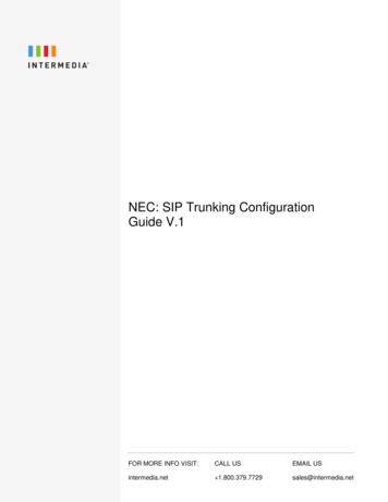
LBI-38987SCOPETABLE OF CONTENTS (Continued)PageCLEAR VOICE CHECKOUT . . . . . . . . . . . . . . . . . . . . . . . . . . . . . . . . . . . .8Locally Initiated Call . . . . . . . . . . . . . . . . . . . . . . . . . . . . . . . . . . .8Multisite Initiated Call . . . . . . . . . . . . . . . . . . . . . . . . . . . . . . . . . .8DIGITAL VOICE CHECKOUT . . . . . . . . . . . . . . . . . . . . . . . . . . . . . . . . . . .8Locally Initiated Call . . . . . . . . . . . . . . . . . . . . . . . . . . . . . . . . . . .8Multisite Initiated Call . . . . . . . . . . . . . . . . . . . . . . . . . . . . . . . . . .8LED INDICATORS . . . . . . . . . . . . . . . . . . . . . . . . . . . . . . . . . . . . . . . . . . .8LIST OF FIGURES AND TABLESThis manual provides instructions for configuring theEricsson GE Trunking Card (GETC) for use in a SingleChannel Autonomous Trunking (SCAT) station. The information presented in this manual is applicable to EDACSSCAT stations using the MASTR II, IIe or MASTR III repeaters. The manual provides instructions for installing theSCAT GETC hardware, firmware, and software. It also provides instructions for setting up the GETCs and for performing a functional checkout of the GETC’s.nel information until a radio requests a channel. The SCATrepeater then assigns itself as the working channel and begins routing audio. When the call is complete, the SCATchannel resumes operating as the control channel.SCATGETCMASTR II/IIe/IIIRepeaterINTRODUCTIONSCAT is a unique application of a GETC shelf that isconfigured as an option to an EDACS Repeater. The SCAToption allows a single repeater to alternately perform theControl Channel or Working Channel functions. This extends the trunked operation into difficult areas such as ravines, tunnels, etc. and extremely low traffic density areassuch as shopping malls.Figure 1 - Stand-alone SCAT . . . . . . . . . . . . . . . . . . . . . . . . . . . . . . . . . . . . . .1Figure 2 - Network SCAT Station . . . . . . . . . . . . . . . . . . . . . . . . . . . . . . . . . . . .1Figure 3 - Downlink to CEC/IMC Communication . . . . . . . . . . . . . . . . . . . . . . . . . . .2Figure 4 - SCAT to Downlink Communication . . . . . . . . . . . . . . . . . . . . . . . . . . . . .2Figure 5 - GETC Phone Line Level Adjustments . . . . . . . . . . . . . . . . . . . . . . . . . . . .3Figure 6 - Station GETC (19D904266) Jumper Locations . . . . . . . . . . . . . . . . . . . . . . .4Figure 7 - Turbo Board Programming . . . . . . . . . . . . . . . . . . . . . . . . . . . . . . . . . .4The SCAT channel may be configured as stand-alonesystem or as part of a multisite trunking network.Figure 8 - Personality Programming . . . . . . . . . . . . . . . . . . . . . . . . . . . . . . . . . .6STAND-ALONE SCATFigure 9 - Switch Settings for Personality Programming Mode . . . . . . . . . . . . . . . . . . . .6Figure 10 - Sample SCAT Personality . . . . . . . . . . . . . . . . . . . . . . . . . . . . . . . . . .7Figure 11 - Sample SCAT Wide Area Digital Personality (optional) . . . . . . . . . . . . . . . . . .7Figure 12 - SCAT GETC Switch Settings . . . . . . . . . . . . . . . . . . . . . . . . . . . . . . . .8Figure 13- SCAT Downlink Switch Settings . . . . . . . . . . . . . . . . . . . . . . . . . . . . . .8Figure 14 - MASTR II (IIe) EDACS Network SCAT Interconnection Diagram . . . . . . . . . . . .9Table 1 - Jumper Settings . . . . . . . . . . . . . . . . . . . . . . . . . . . . . . . . . . . . . . . .5Table 2 - LED Indications, No Activity . . . . . . . . . . . . . . . . . . . . . . . . . . . . . . . . .8Table 3 - LED Indications, Clear Voice Local Call . . . . . . . . . . . . . . . . . . . . . . . . . . .8Table 4 - LED Indications, Clear Voice Multisite Call . . . . . . . . . . . . . . . . . . . . . . . . .8Table 5 - LED Indications, Digital Voice Local Call . . . . . . . . . . . . . . . . . . . . . . . . . .8Table 6 - LED Indications, Digital Voice Multisite Call . . . . . . . . . . . . . . . . . . . . . . . .8Table 7 - LED Indications, Summary . . . . . . . . . . . . . . . . . . . . . . . . . . . . . . . . . .8SCAT systems are available for all EDACS widebandconfigurations: VHF, UHF, and 800 MHz.The stand-alone SCAT consists of a standard EDACSStation with the GETC reconfigured for SCAT operation(SCAT firmware installed in the GETC) as shown in Figure1. In this configuration, the repeater transmits control chan-Figure 1 - Stand-alone SCATNETWORK SCATThe second configuration is a Network SCAT channelused as part of an EDACS Multisite system.Each Network SCAT channel requires a standardEDACS station with the SCAT station option (XXCP3Y).This option adds a SCAT Downlink GETC, SCAT firmwarefor both the station GETC and the SCAT Downlink GETC,and a SCAT GETC interconnect cable to the EDACS station.In this configuration, the SCAT station is connected to theConsole Electronics Controller or Integrated Multisite andConsole Controller (CEC/IMC) as shown in Figure 2. EachSCAT channel has its own Downlink and audio/data interface into the CEC/IMC.4 wire 9600 baudSCAT DownlinkGETCData LinkUplink CETCSCATGETCCEC or IMC4 wireAudioMASTR II/IIe/IIIRepeaterCONTROLAUDIOFigure 2 - Network SCAT StationCopyright May 1994, Ericsson GE Mobile Communications Inc.1
LBI-38987The CEC/IMC controls and routes SCAT calls, allowingthe user to enjoy trunking features and the same trunked userinterface. The CEC/IMC must be configured with a site interface (MSZM3R) for the SCAT system.SCAT sites. However, use of the Centralized Telephone Interconnect System (CTIS or Jessica) is available in the multisite configuration.SCAT and DownlinkNOTEIn MASTR III systems, a cable (19D903880P10) isadded to allow easy access to the MIII Tx and RxAudio (J101). This cable is routed from from theMIII Interface Board J101 to the Downlink GETCTB10 pins 1, 2, 3, and 4.SCAT provides the control functions to implementEDACS access to the SCAT service area. The Downlink isessentially a message conduit providing a data communication path between the SCAT and the CEC/IMC.The Downlink’s modem data is synchronous at 9600baud using the full duplex operating mode. Data flows simultaneously in both directions as illustrated in Figure 3.Wide Area Digital OptionThe Wide Area Digital option (SXSF7A) enables the SCATstation to support Digital Voice communications. A hardwareoption (SXMD1D) provides an additional Rockwell Modemfor the SCAT GETC. This enables the SCAT GETC to sendand receive 9600 baud digital voice to the CEC/IMC using thefour wire audio line.NOTEThe SCAT software (344A3835) must be Group 2 orlater to support Digital Voice communications.OPERATIONAs a result of the SCAT station using only one channel,only one conversation can occur at any one time through theSCAT site. While the SCAT site is busy, every call request(mobile request or console request) is queued. The mobileradio generates the Call Hold Off queue tone and automatically places a call request upon completion of the first call.Only console request for the active group will be processedimmediately.SCAT operation can only be performed by radiosequipped to use a SCAT channel. SCAT only supports lateentry for group calls.The following radios are currently SCAT compatable:Radio TypeSoftware VersionAlpha 3, 344A(3705, 3703,4415, 4421, 4419, 4614)All Group 12PCS344A4272G1RANGR19A149268G21The SCAT channel and SCAT radios are designed tominimize the overloading of the inbound SCAT channel byprioritizing all calls. This allows the system to respond toemergency calls immediately upon availability of the channel.Except for interconnect calls, all group and individualcalls appear as transmission trunked calls to the radio and theCEC/IMC. This assures the mobile’s quick return to theControl Channel. Local interconnect is unavailable on2 TQ-3360 programming cable. Male DB-25 to female DB-9 adapter. Software distribution diskette 344A4414. Oscilloscope.CONFIGURATIONThe configuration process involves the following steps andshould be completed in the order presented:1.Hardware Installation - The Hardware Installationstep verifies proper installation of GETC hardwareand provides instructions for installing the configuration jumpers.2.Firmware Installation - This step provides instructionsfor installing the GETC operating firmware.3.Software Installation - This step provides instructionsfor installing the Turbo Board software.4.Personality Programming - This step provides instructions for programming and storing system configuration data in the GETC.5.Operational Checkout - This step provides instructions for setting the dip switches S1 through S3 andfor verifying GETC operation when the configurationis complete.RELATED TxCEC/IMCUplinkFigure 3 - Downlink to CEC/IMC CommunicationIt may be necessary to consult one or more of the followingdocuments during the installation process. These manuals willalso provide additional guidance if you encounter technical difficulties during the configuration process.LBI-38822 - Turbo Board (GETC-1e) Maintenance ManualLBI-38894 - GETC Trunking Card Maintenance ManualThe SCAT to Downlink format is asynchronous at 19.2Kbaud using the half duplex operating mode. Data flows inone direction at a time as shown in Figure 4.BSLDataBlocksSCATLBI-38984 - EDACS System Manager User’s GuideBSLDownlinkRxTxORBSLSCATRxLBI-38896 - EDACS Site Downlink and CEC/IMC UplinkConfiguration ManualLBI-38988 - EDACS Station GETC Configuration ManualHARDWARE INSTALLATIONLBI-39024 - CEC/IMC Manager (MOM), Version 3.xx Operations Guide.Each SCAT channel requires a standard EDACS Stationwith a SCAT station option. The Stand-alone SCAT requires asingle station GETC setup for SCAT operation. The NetworkSCAT requires a station GETC and downlink GETC. BothGETCs must be setup for SCAT operation. This section includes hardware installation instructions for both the Standalone and Network SCAT GETCs.SRN-1009- Software Release Notes for GETC SCAT SoftwareSRN-1010- Software Release Notes for Turbo Board SoftwareTQ-3357- GETC Shelf Programming ManualBSLDownlinkDataBlocksTxStand-alone SCAT GETCFigure 4 - SCAT to Downlink CommunicationEQUIPMENT REQUIREDSince these two protocols are different, the Downlinkconverts from one format to the other. In addition, both theSCAT and Downlink perform data error detection and correction, general control of timer and IO functions (DIPswitch, LED’s, UART’s, etc.), receive and transmit buffermanagement, message scheduling, and Turbo interfacing.The following equipment and software may be required toconfigure the GETC: IBM compatible PC with at least 640K memory,monitor, and keyboard. Hard disk is recommended; but, not required. Serial Port configured as either COM1 or COM2.Typically, a Stand-alone SCAT GETC is installed in the station cabinet just above the station’s radio assembly. The GETCis mounted within a slide out shelf measuring 1.75 inches high(one rack unit) by 19 inches wide.Installation or removal of the shelf sub-assemblies involvessliding the GETC shelf out of the cabinet and into the serviceposition. This position allows access to the shelf’s sub-assemblies. Install all components with the appropriate screws, nuts,and washer hardware. Refer to the MASTR II, IIe, or MASTRIII Application Assembly Diagrams for detailed information oninstalling the GETC Shelf.
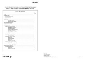
LBI-38987Observe basic safety precautions to prevent injury or equipment damage.Network SCAT GETCThe Network SCAT option consists of a SCAT GETC, aDownlink GETC, a GETC interconnect cable and SCAT firmware for both GETCs. The interconnect cable provides theconnection from the SCAT GETC to the Downlink GETC using their Backup Serial Ports. Both the SCAT and DownlinkGETCs are configured with a Turbo Board for additional memory and processing capability.Data communication between the SCAT Downlink GETCand the CEC/IMC Uplink GETC is carried on a four-wire,data grade, type 3002 audio circuit. As shown in Figure 2, theSCAT Site is configured as a dedicated site connected to theCEC/IMC through the Uplink GETC. Therefore, the maximum number of SCAT channels on a multisite network isequal to the maximum number of sites allowed on theCEC/IMC.GETC Logic Board InstallationThis manual assumes that the Logic Boards in both GETCsare previously installed, setup for the default configuration(800 MHz EDACS), and fully operational. If for any reason aGETC Logic board is suspect, refer to Maintenance manualLBI-38894 for detailed instructions on removing, replacing,and testing the GETC Logic Board or the Regulator Board.Turbo Board InstallationThis manual assumes that both GETCs have the TurboBoard installed at the factory and they are fully functional. Ifthe Turbo Board is not installed or you encounter problemswhile installing the Turbo Board software, refer to LBI-38822and SRN-1010 for detailed instructions on removing, replacing, and testing the Turbo Board.Rockwell Modem InstallationA Rockwell Modem is always required in the DownlinkGETC. Use the following procedure to install the modem if itis not already installed:NOTEIf the SCAT station is setup to use the Wide Area Digital option, a Rockwell Modem must also be installed inthe SCAT GETC. This allows the station to send andreceive digital information to the CEC/IMC throughthe audio path.1.Remove GETC power.2.Remove the Turbo Board, refer to LBI-38822.3.Plug the Rockwell Modem into J3 on the GETCLogic Board.4.Install four insulators (A4035306P25) underneath themodem board and four insulators above the modemboard at each screw hole.T1Remove and discard the two nylon washers previously used as spacers.R36604Reinstall the Turbo Board.D115.6.7.ParallelData BusReceiving Half ofTelephone LineJ6-07 J6-068Apply power to the GETC.9.Adjust the audio line levels as follows (refer to Figure5):a.b.551 2J111 9U18B4558576D13D12J7J8J6J19T1T2Transmit Level Adjustment (R2)Transmit Data Test Point (Digital, TP105)R2R1EPROM (U2)11U18Receive Level Adjustment (R1)Receive Level Test Point (Analog, U18-1)Transmit Level Test Point (Analog, U18-7)1U212R38220TP105Receive DataTest Point(Digital, TP107)6R146604TxLevelR21KJ10J27Verify the presence of demodulated signal data atTP107.There are a few jumpers on the GETC Logic Board whichmust be re-configured depending on the GETC application. Toproperly configure the GETC jumpers, refer to Table 1 and install or remove jumpers according to the intended GETC application. The location of the jumpers may be found using theboard layout diagram in Figure 6 or by referring to the fullscale GETC Diagrams at the end of the manual.RockwellModem19A705178Telephone LineLevel AdjustmentsMonitor U18 pin 1 and adjust the receive levelpotentiometer R1 (located on the GETC LogicBoard) for 400 mVpp as measured with an oscilloscope (85 mVrms if using an RMS Voltmeter) .Jumper Installation8T2Tx 212R15KAdjust the transmit level potentiometer R2 for themaximum output level allowed by the phone line,microwave link, or equivalent communicationline. For telephone lines, adjust R2 for .77 Vrms(0 dBm) across J6-8 and J6-9. For microwavelinks, adjust R2 for -10 dBm across J6-8 and J69.Transmitting Half ofTelephone LineJ6-09 J6-08TP105UnmodulatedTx DataSerial Data19 RxJ49c.D0D1D2D3D4D5D6D7U196Install jumpers on P11-pins 1&2 and on P12-pins1&2.8.TP107DemodulatedRx Data4567891 01 1U1U3U19J31TP107R141 and R31 are unused adjustments in the CNI configuration.U4R141S1S2S3R311U35Dip SwitchesS4Reset SwitchLED IndicatorsL1 L2L3L4 L5L6L7Figure 5 - GETC Phone Line Level Adjustments3
LBI-38987FIRMWARE INSTALLATIONThe firmware installation procedure involves installingthe latest version of the SCAT EPROM (344A3835) intoboth the SCAT GETC and the SCAT Downlink GETC.NOTEThis software is subject to change resulting from improvements or enhancements. When upgrading thesoftware, the procedures provided in the accompanying software release notes takes precedence over thismanual.The PC reads data from the files on the 344A4414 diskette transfers the data to the Turbo Board microprocessorthrough connectors J103 and J104 at the rear of the GETCShelf.J10J27J29Running the "load1e.exe" executable program seriallymoves data from the "1etop.hex" and "1ebot.hex" files tothe code segment of the Turbo Board’s 18J26111R11J6911J6211J21 11J541J681J72Perform the following steps to install the SCAT GETCfirmware. Repeat the process to install the SCAT firmwareinto the SCAT Downlink GETC:1.Remove power from the GETCs and place theGETC shelves in the service position. This will allow access to the EPROM.2.Remove the Station GETC EPROM U2.3.Install the SCAT GETC EPROM into the XU2socket (ensure the EPROM’s pin 1 is properlyaligned with pin 1 on the socket).4.5.Restore power to the GETC.When both GETCs have the SCAT firmware installed, proceed to the Software Installation procedure.SOFTWARE INSTALLATIONThis step provides instructions for programming theTurbo Boards installed in the SCAT and SCAT DownlinkGETC. The installation process uses the software diskette344A4414, an IBM compatible personal computer (PC), andan interconnecting cable AT GETCLED IndicatorsU35Dip Switches19D904266EPROM InstallationU4J55S11J25J6011If an error occurs, check connectors and cables. Cycle S2 and S3 from the front position, to the rear position, and again to the front position. If the PCcontinues to indicate an error, refer to the TurboBoard Maintenance Manual LBI-38822.11NOTEJ131J46111111R2J611J28 J481J12The "1ecrc.hex" file provides Cyclical RedundancyCheck (CRC) information for use in error checking and verification during the file transfer or "programming" process.Any errors encountered during this procedure generally indicates a defective communication link between the PC andTurbo Board.1S4Reset SwitchL1L2L3 L4 L5L6L7Figure 6 - Station GETC (19D904266) Jumper LocationsPreparationPrepare the PC for programming the SCAT GETC TurboBoard by performing the following steps:1.CableTQ-3360Connect the TQ-3360 programming cable from thePC’s serial port connector to the GETC Shelf connector J104 (see Figure 7). (A DB-25 to DB-9adapter may be needed.)Harness3.Using standard DOS commands or a software filemanager, create a directory named "LOAD1E" onthe PC’s hard drive.Software Disk344A4414 load1e.exe 1etop.hex 1ecrc.hexJ10J27LOAD1EJ9J7J8J5J19T1U1T2J49ToCOM PortMake "LOAD1E" the current default directory andcopy the following files from the software disketteinto the "LOAD1E" directory:19C337712G1J3J22.J103 J104S2R111U181U2U1U3S31U191J3TP107U4U2S1Contains The LOAD1EFile Transfer Utilityand Turbo Board'sExecutable CodeS2S3S4L1Turbo BoardL2L3L4L5L6L7Lightning GETCGETC Shelf 19D901868G3 1ebot.hexFigure 7 - Turbo Board Programming
LBI-389874.Table 1 - Jumper SettingsJumper settings for SCAT GETC and SCAT Downlink GETC (19D904266 &22&32&3Legend:LSD Low Speed DataHSD High Speed DataFUNCTIONReceive data from 9600 baud modem board.Clear to send from 9600 baud modem board.BSL Tx output to BSL Rx input.Master site controller path selection enable.Backup site controller path selection enable.BSL selection enable.LSD encode path enable.LSD decode path enable.Enable high-speed data acquisition rate control, HSACQ.BSL selection (Failsoft) enable.LSD encode path enable.Lock-detect path enable.Sync line input path enable.Enable site controller RxD, J8-4.Use for 256K or 512K EPROM.INTO for voter concentrator.BSL select.BSL select.Enable tone control for voted systemMorse code ID enable.TxD polarity select.RxD polarity select.Enable MODCNTL local control.Selects proper receive telephone line input impedance.Selects Local (on)/Remote (off) control of station PTT.Enables COMB PTT IN.Enables telephone modem RTS control.Selects internal oscillator.Enables NOR gate U22B for PST applications.Selects CAS input to microprocessor.BSL Backup Serial LinkMSL Main Serial LinkRxD Receive DataTxD Transmit DataFor Wide Area Digital Voice option (Rockwell Modem installed), move jumpers to 1 & 2.** For UHF applications, OMIT P26.1.Move switches S2 and S3 to the "run" position (toward the back of the GETC shelf).2.Press S4 to reset the GETC.3.The Turbo Board LEDs, D1 and D2, will light indicating the station code is executing.The Turbo Board LEDs D1 and D2 should turnOFF indicating that the Turbo Board is in the programming mode.4.Disconnect the TQ-3360 programming cable uponsuccessful completion of the programming procedure.Programming ModeThis procedure downloads the Turbo Board software tothe microprocessors U1 and U2 on the Turbo board.For additional information on programming the TurboBoard, refer to the Turbo Board Maintenance Manual LBI38822 and Software Release Note SRN-1062.SCAT Downlink GETCNOTERe-programming the GETC Turbo Board will not alter previously stored Personality Data. When Personality Data is present, "load1e.exe" clears andperforms CRC functions over the code portion ofmemory only. The "load1e.exe" also stores CRCdata in the DS-2250’s memory for future data corruption checks.The procedure for programming the Downlink GETCTurbo board is exactly the same as the SCAT GETC.1.Repeat the SCAT GETC Software Installation process for the SCAT Downlink GETC Turbo board.When both GETCs have been programmed, proceed tothe Personality Programming procedure.PERSONALITY PROGRAMMING1.Enables HSD path.Use for 512K EPROM.Selects 11 MHz clock Freq. for 9600 baud data.NOTES*5.Move the Turbo Board run/load switches S2 andS3 to the load position (toward the front of theGETC shelf). The front position of S2 and S3places the processors U1 and U2 into the programming mode. If either switch is already toward thefront, move the switch to the rear and then back tothe front position.Execute the "load1e.exe" program on the PC andfollow the on screen instructions.The "load1e.exe" program loads the file"1etop.hex" into the Turbo Board’s upper half ofmemory for use by the top processor U1.2.Monitor the PC’s on screen instructions andprompts.3.When directed, move the TQ-3360 programmingcable from the GETC Shelf J104 to J103.4.The PC will indicate it is loading the "1ebot.hex"file into the Turbo Board’s lower half of memoryfor use by the bottom processor U2.Normal ModeUpon successful completion of the programming mode,the PC displays a "FINISHED" message. It will also provide instructions to switch S2 and S3 to the rear position fornormal operation.Personality refers to the system configuration data storedin the GETC’s memory. The GETC’s Personality includessystem configuration information such as channel frequencies, call parameters, operating modes, and identification information.The Personality Programming process stores the Personality data in EEPROM U35 on the GETC Logic Board(SCAT GETC’s with EPROM 344A3835G1 or G2). Thisprocess involves using the TQ-3357 (Version 3.00 or later)GETC Shelf PC programming Guide which includes theprogramming software.NOTEThis software is subject to change resulting from improvements or enhancements. The instructions contained in this manual are for guidance only. Whenprogramming the personality, the detailed instructions contained in TQ-3357 and the accompanyingsoftware takes precedence over this manual.5
LBI-389874.CableTQ-3360J100Read the existing personality from the SCAT GETCto the PC. If the personality does not exist, retrievethe sample SCAT Personality (shown in Figure 10)from the PC. Change the personality parameters asrequired.Wide Area Digital OptionThe Wide Area Digital option is activated at the factory using a unique code for each repeater. This code is stored withthe GETC Personality.Harness 19C336863G2NOTEJ10J27Software Disk344A3466G4GTCJ9J8J5J7J8U1J19T1The personality data for SCAT Downlink GETCmust be the same as the SCAT GETC.T2J49J49ToCOM 1R111Thus changes to the personality should be made by readingthe existing personality, modifying the data, and writing themodified data back to the GETC. Figure 11 is an example ofthe SCAT Wide Area Digital Personality.U181U2U1U3OPERATIONAL CHECKOUT11U1915.J3J3TP107TP107U4U2S1S2S3After entering the personality parameters, select the"Program Card" function to program the personalityinto the GETC.S4L1L2L3L4L5L6L7Verify that the GETC has properly stored the personality data by selecting the "Read Unit Into File" function while in the Current Personalities Screen.DIP SWITCH SETTINGS7.After completing the programming, save the revisedpersonality to disk.The GETC DIP Switch settings depend on the GETC’s usage (SCAT GETC or SCAT Downlink GETC), channel, andfrequency (Mastr II and IIe only). Set the GETC dip switchesusing the following procedures:combination with the dip switch settings, places theGETC into the Personality Programming mode.8.Reset the DIP switches and press S4 to reset theGETC.Verify that front panel LEDs L3, L4, and L5 areON, this indicates the GETC is ready for programming.9.Disconnect the TQ-3360 cable and verify GETC operation.Turbo Board6.Lightning GETCGETC Shelf 19D901868G3Figure 8 - Personality ProgrammingPreparationPrepare the PC for Personality Programming by performing the following steps:1.Connect the TQ-3360 programming cable from thePC’s serial port connector (COM1/COM2) to theSCAT GETC Shelf connector J100 (see Figure 8).(A DB-25 to DB-9 adapter may be needed.)2.Set the GETC dip switches S1, S2, and S3 for theprogramming mode as shown in Figure ont of GETCC Closed45CCOOPENLegend:378CCOOPENO OpenFigure 9 - Switch Settings for Personality ProgrammingModeProgramming the PersonalityProgram the personality into the SCAT GETC or theSCAT Downlink GETC using the following procedures:1.6NOTE2.Reset the GETC by either cycling power or pressing the GETC RESET switch S4, located just below the dip switches. Resetting the GETC, inBe sure the dip switch settings correspond to thePersonality data created.CEC/IMC Personality ConfigurationLED IndicatorsL1L2L3L4L5L6L7Programming Mode Legend:3.6Verify that the GETC is operating correctly by performingthe following steps: OFF ON* FLASHINGFollowing the instructions in TQ-3357, select the"GE" directory and execute the "GTC" command.After a brief introductory screen, the Current Personalities Screen appears.At the System Manager, configure the SCAT groups asTRACKED to maximize the availability of the SCAT channel.As a TRACKED group, the SCAT channel only receives requests from the CEC/IMC for groups that are logged into theSCAT system. The CEC/IMC bypasses the SCAT system withother multisite calls making the SCAT channel available for users within the SCAT system coverage area. Refer to LBI38984 for System Manage
SCOPE This manual provides instructions for configuring the Ericsson GE Trunking Card (GETC) for use in a Single Channel Autonomous Trunking (SCAT) station.