Transcription
AC 2011-152: TEACHING CAD MODELING USING LEGODerek M Yip-Hoi, Western Washington UniversityDerek Yip-Hoi has a Ph.D. in Mechanical Engineering from the University of Michigan. He has broadexperience in CAD/CAM and geometric and solid modeling from research and teaching experiences atUM and the University of British Columbia. Currently he coordinates the CAD/CAM instruction in theEngineering Technology Department at Western Washington University.Jeffrey L. Newcomer, Western Washington UniversityJeffrey L. Newcomer is a Professor of Manufacturing Engineering Technology at Western WashingtonUniversity. He received B.S. (1988) and M.Eng. (1989) degrees in Aeronautical Engineering, a M.S. inScience and Technology Studies (1993), and a Ph.D. in Mechanical Engineering (1994) from RensselaerPolytechnic Institute. He is engaged in research to improve instruction and assessment in engineering,with an emphasis on engineering fundamentals such as mechanicsPage 22.1374.1c American Society for Engineering Education, 2011
Teaching CAD Modeling Using LEGO This paper explores the potential of using LEGO to support teaching CAD modelingtechniques to engineering technologists. There are a number of advantages to using this medium.First, LEGO building blocks come in a wide variety of shapes from the simple standard formsto more complex special purpose blocks found in kits such as Racers or MindStorms. From aCAD modeling perspective the features used to model these blocks can therefore range from thesimple pad/pocket type to more involved sweeps and multi-section shapes (lofts). Students canlearn and practice bottom-up assembly modeling techniques by building models using libraries ofstandard blocks. They can also model custom blocks using the design-in-context approach. Thiscan support creativity in generating new LEGO kit concepts. Since LEGO blocks and kits areeasily available and affordable, it is possible for students to create a CAD model for which aphysical prototype can be built. With the availability of rapid prototyping equipment (e.g.Stratasys FDM technology) or use of a service bureau, custom blocks can also be included inthese prototypes. This introduces students to Design for Manufacture and Assembly concepts asthese custom blocks must be designed with appropriate wall thicknesses and stiffening, and withappropriate clearances and fits to assemble to standard blocks. The ability to do this adds to theappeal that LEGO has for many students who are well familiar with their use. Experiencesfrom implementing a LEGO based CAD project in a freshman course that teaches EngineeringDesign and Graphics will be used to underscore the benefits of using this approach.IntroductionCAD instruction is a required part of the curriculums of many engineering and technologydisciplines. In most cases it has replaced manual drafting instruction as the technique forgenerating engineering drawings. The state-of-the-art enables the creation of a 3D model using afeature-based parametric modeling environment. This is well suited for capturing design intent.The designer must select features, create the sketches that construct them, and specify thedimensions that control size (parameters) strategically to allow the types of changes that mayoccur without “breaking” the model. CAD courses introduce students to the underlyingmethodologies of 3D parametric modeling. These methods though implemented within differentapplications (e.g. SolidWorks, CATIA, Unigraphics, Inventor) can be viewed as generic buildingblocks for the technology. These include: SketchingDimensioning and constraining sketchesDecomposition of part geometry into modeling featuresCapturing Design IntentAssembly constraints (Bottom-up modeling)Design-in-Context Assembly Modeling (Top-down modeling)Use of standard components (Component Catalogues and Libraries)Generative Drafting MethodsPage 22.1374.2Within an engineering or technology program that is focused on product development, animportant goal is to complement instruction in the methodology and the mechanics of CADsystem use with modeling realistic components whenever possible. This should at the end of the
day introduce students to the concepts of Design for Manufacture (DFM) and Assembly (DFA).They should quickly come to appreciate that it is relatively easy to construct a product that maynever exist as more than a digital model, but that it is another thing to create a model that mustbe fabricated. This is a challenging pedagogical goal particular for introductory courses wheremany students are not only unfamiliar with CAD technology but also lack a fundamentalunderstanding of fabrication processes.In this paper a new concept to CAD instruction is being proposed that utilizes LEGO buildingblocks. The goal is to utilize a readily accessible and familiar product that is simple enough bothin geometric structure and in the application of DFM and DFA principles so that students canreadily create both a digital model and physical prototype. Students get to see their CAD models“come to life” but must take steps to ensure that the desired result is achieved.Use of LEGO in Engineering EducationThe use of LEGO blocks in engineering education is not uncommon. A commonapplication involves building programmable mobile robots from LEGO . These applicationsvary only in specifics and level of application. Lai-Yuen1 and Jaksic and Spencer2 presentexamples of LEGO use in upper division courses, Mehrubeoglu3 and Want et al.4 presentexamples of LEGO use in introductory courses, and McGrath et al.5 and Whitman et al.6present examples of LEGO use in pre-college programs to attract students to engineering andscience.A rarer application of LEGOs in engineering education is the use of virtual LEGO environments. In addition to robotics, Lai-Yuen1 also describes the use of a virtual assembly ofLEGO blocks to teach students concepts in micro-manufacturing. Kelley7 describes a similarapproach in which virtual LEGO blocks are used to teach and implement Product DataManagement (PDM) techniques. Pasek et al.8 have developed automation to assemble LEGO blocks as part of a CIM driven LEGO Factory. This utilizes a virtual assembly of LEGO blocks as input to process planning that sequences assembly of the LEGO model in the factory.While these cases involve students creating virtual LEGO assemblies, none of them include thestudents either designing or prototyping new LEGO blocks as part of a creative design processthat develops a new concept.It should also be mentioned that there are a number of software tools available that can beused to build LEGO models using standard blocks. This includes LEGO’s own LEGO DigitalDesigner application9 and LDraw10. The goal of these applications is to assist LEGO practitioners to create and visualize their designs prior to acquiring blocks and building themodel. They also generate instructions to assist in the build. They are not strictly speaking CADapplications and so are not suitable for use in a CAD curriculum. They also do not promote themodeling and fabrication of custom blocks as is proposed in this paper.CAD Instruction that Leads to A Physical PrototypePage 22.1374.3A wide range of instructional material is now available for CAD given the proliferation andaccessibility of the technology. A cursory seach at Amazon.com for example for books dealing
with systems such as AutoCAD or Solidworks yields a large number of options. Numerouspublishers produce texts on CAD systems and there are several that specialize in this area.Professional educational services that teach CAD also offer their materials for use asinstructional purposes within university degree programs in Engineering and EngineeringTechnology. These materials, to different proportions, cover both the methodologies of 3Dparametric modeling and the mechanics of using the interface of a particular system. They use acombination of: Background explanations,Rote exercises (follow the instructions),Independent exercises (do it yourself) driven by dimensioned drawings, andOpen ended projects.An important embedded theme for a curriculum of CAD instruction is that students should bemade aware that their models need to be fabricated. To have CAD instructional material that isstructured around modeling then fabrication of a physical product is challenging. Products thatare complex enough geometrically to provide good practice using the CAD system can have arange of fits that make the creation of a physical prototype difficult. This says nothing of theneed for skill in using fabrication processes to make a prototype. Both an understanding of fitsand exposure to manufacturing processes may not be covered until after CAD instruction in atechnology program.Off-the-shelf instructional materials typically do not place a high emphasis on integrating DFMand DFA considerations into CAD modeling. It is typically open ended projects that provide thebest format for encouraging students to integrate manufacturing considerations into theirmodeling as part of generating a physical prototype. For this purpose, CAD instruction may becombined with some exposure to CAM and CNC programming that allows students to by-passmanual fabrication. However, this leads to a very heavy course content and can distract from thefocus on CAD technology as students must also learn tool path generation and CNCprogramming. A better solution is to utilize Rapid Prototyping (RP) technology. The timeoverhead in building a prototype directly from a CAD model using a process such as FusedDeposition Modeling (FDM from Stratasys) is significantly less than the use of CAM and CNC.As part of an introductory CAD class students using RP get exposure to tool path generation (forlayered manufacturing) and must make some allowances in their modeling if the prototypedcomponent is to fit within an assembly. One limitation is that students must work with materialsthat are used by the RP process which are typically non-metallic e.g. ABS plastic for FDM. Thephyscial prototypes that students create should be functional with the material used by the RPprocess.Why Use LEGO ?Page 22.1374.4An instructional methodology that encourages students to consider fabrication when modelingand that can lead to a physcial prototype is possible using products built with LEGO blocksthat are augmented with custom blocks built by RP. The following summarizes some of theadvantages of using this approach.
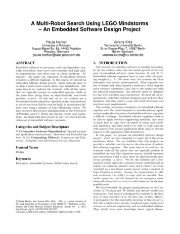
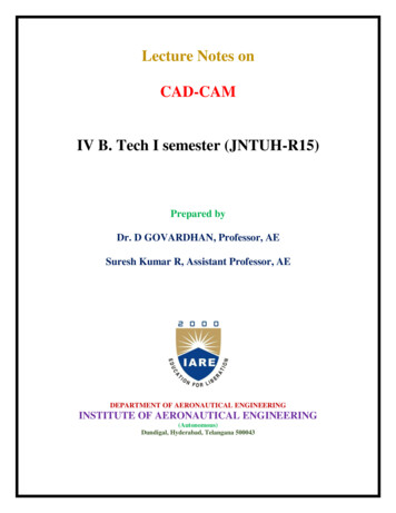
Familiarity and Accessibility:LEGO is a concept that is familiar to most students. This in itself provides a connection toreality. Many exercises in off-the-shelf instructional material are not based on realcomponents and students may not be familiar with those that are. LEGO blocks can easilybe made available to students as part of their modeling exercises, to compliment paperdrawings and instructions with a physical artifact. Supports Teaching Different CAD Modeling Techniques:As anyone familiar with LEGO can attest to, there is a large and ever growing set of blocksthat are available. These range from the simple blocks and flats to styled pieces that arespecifically designed for promoting the theme of a kit. The features present in these thereforecorrelate with the feature set available in a typical parametric CAD system. For example, asimple 2 x 2 block can be used to develop exercises that use the Pad and Pocket feature. Inaddition, the studding presents an opportunity to use the Patterning tool. More styled blocksthat are developed to support the theme of a LEGO kit would require the use of moreadvanced features such as a Rib (sweep) or Multi-Section Solid (loft) feature. Exercises inmodeling various types of blocks can easily be created to support instructional objectives.LEGO also naturally supports the instruction of assembly modeling techniques. Supporting and Managing Creativity:Students are typically more motivated when they are given an assignment where they canexercise creativity. Open-ended projects provide this opportunity. However, this can be adouble edged sword if not properly managed. As evidenced by the vast assortment ofLEGO themes and kits that are available on the market, the LEGO concept does generatecreativity. At the same time being a modular approach to constructing a product it allowsconstraints to be placed by the instructor that help to manage the effort. One technique usedfor this is to require students to build a Platfrom around which their concept is to bedeveloped. Figure 1 shows an example of a platform and a concept developed around it.Platforms can be constrained by the theme of the project and the number and types of blocksused. This provides control over the size and effort put into creating a model.Figure 1. Platform ConceptComplementing the Virtual with a Physical Result:Ease of access of LEGO blocks makes creating a physcial prototype feasible. In additionthe use of RP allows students to see their concepts evolve from brainstorming, throughPage 22.1374.5
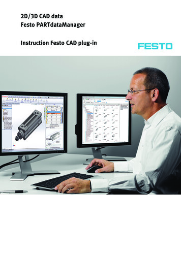
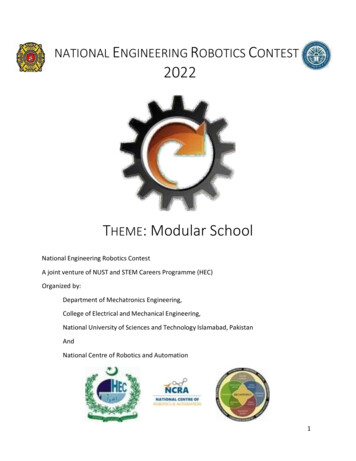
sketches and detailing with CAD models to a physcial result. The connection between theCAD model and a final, physcial result is thus reinforced in the minds of the students. The Ability to Incorporate Manufacturing Considerations:Custom blocks that are developed to create a LEGO concept must fit with standard blocksusing the patented stud mechanism. This requires students to include mating features and touse appropriate dimensions and clearances on their blocks to facilitate assembly. Figure 2shows stud and recess sizing guidelines based on the FDM RP process that are given tostudents for incorporation in their models. Students in the design of blocks are encouraged toinclude features that assist in injection molding, the process that would ultimately be used formass production. These features include, draft, appropriate wall thickness and stiffeners. TheRP process also places requirements such as the impact of orientation on surface finish.Consideration of these requirements provides an introduction to DFM and DFA.Figure 2. Dimensional Guidelines for LEGO Stud Mechanism to mate with FDM Built Parts Introduces Toolpath Planning:This is a critical component of understanding machining processes. Students inManufacturing and Plastics Engineering Technology do courses in CAM and CNCprogramming. The use of process planning software to create a “job” for a RP machinerequires the generation of tool paths that guide the build head of the machine.Page 22.1374.6Figure 3. Tool Path Generation for FDM RP Process to Build a LEGO Compatible Part
Though 2D and additive, students are introduced to the concept of how a tool needs to beprogrammed for moving it over a region to generate a shape. Figure 3 shows examples ofslice boundaries and toolpath fill patterns generated by process planning software for creatingABS plastic components on a Stratasys FDM RP machine.Strategy for Introducing LEGO into CAD EducationA two step strategy is being adopted for integrating the use of LEGO into the introductoryCAD instruction in the Engineering Technology Department at Western Washington University.The steps are as follows: Develop a LEGO-Based Team Project for Introductory CAD Course (ETEC 113)Integrate Exercises that Require LEGO Block Modeling into Instructional MaterialsA LEGO-Based Team ProjectThe goal of this project is to provide an experience for students to work together in applying thedesign process to create a physical product. As part of the detailed design phase in the project,CAD modeling of the product is required. Fabrication involves construction of customcomponents from ABS plastic on RP machines and assembly with standard components. Earlierefforts at running this project led to significant variability in the quality of the results obtainedfrom different groups. Choices of project topics included products such as CO2 cars, flash lightsand ergonomic hand tools. These were selected in part because they contain custom componentsmade from plastic that can be fabricated using ABS on FDM machines that are available for thestudents to use. However, each choice had its drawbacks. Students are drawn to the “CO2 Cars”(the races at the end of the term are always a big event) and are able to exercise significantcreativity in developing their designs. However, it is difficult to ensure that each student gets toparticipate in modeling the design in CAD since most of the work is focused on a single customcomponent, the body of the car. Flashlights and ergonomic hand tools provide more substancefor incorporating DFM and DFA considerations. There are also more components to model.However, they are less appealing to students. Developing designs that incorporate properassembly features that enable custom built and standard components to come together properlyin a final prototype is hard to consistently control.Page 22.1374.7A LEGO-based project has replaced these earlier efforts and is undergoing refinement in currentofferings of ETEC 113. The steps that must be completed by each team in arriving at theseresults include: Conceptual Design Final Design Selection and Refinement Integration of DFM and DFA Requirements Detailed Modeling of Custom Blocks Process Planning of Custom Blocks Fabrication of Custom Blocks on an FDM RP Machine Assembly of the Prototype Documentation Generation
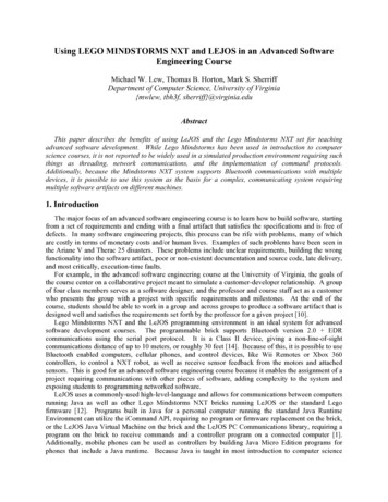
Figure 4. Examples of Student Project CAD Modeling and PrototypingFigure 4 gives some additional examples of student work from this course. Illustrated areexamples of platforms, final detailed CAD assembly models and the assembled prototypes withcustom blocks. Figure 5 shows examples of concepts for these designs that were developed aspart of the process that is followed.Page 22.1374.8The results show that the reasons identified previously to use a LEGO approach are in factjustified. This is particularly true in achieving a process where a CAD model leads to a physicalprototype, a necessity that will be reinforced in many other courses that students will take in theirprograms at Western Washington University and also in their workplace upon graduation.Further, the students are introduced to the importance of considering manufacturing in theirdesign work and that modeling and fabrication are two steps in a much larger productdevelopment effort that includes more abstract activities such as conceptualization, ranking andrefinement. More details of the experiences running this project can be found in a previouslypublished paper11.
Figure 5. Examples of Concepts from Which Design Were DevelopedCurrent offerings of ETEC113 are incorporating some refinements to the project that aredesigned to improve the final result and overall experiences of the students. These are: Provide Sample LEGO Kits as Examples and Sources of Building Blocks: The priorstrategy was to provide each team with a set of standard blocks and wheels that they couldconfigure to build their platform. However, this left too much room for teams to decide onsize and shape of their final concept. In some cases this resulted in non-LEGO like resultswith oversized or over stylized custom blocks. With three LEGO Racer kit samples, eachgroup will get to see the optimal size and style of the custom blocks they should create.Further they will be able to mix and match these blocks in developing the platform that theirconcept will be built around. Teams will also be allowed to use the more generic blocks thatmany have access to. Over eagerness will be tempered by the requirement that all blocksused must be modeled. A library of CAD models for standard blocks and wheels alreadyexists for this purpose. It is hoped that this refinement will help improve consistency and thelevel of detail in custom blocks and the overall final assembly. Include Independently Graded Individual Activities in the Project: Team projects are oftencarried by one or two individuals who do the majority of the work. While this may be a truereflection of what happens in the real world, it is important that students are taught theimportance of full participation and contribution to a project’s success. To achieve this goalseveral deliverables of the team project will require individual effort that will be graded foreach student. These are:Page 22.1374.9o Concept Generation and Sketching: Each student will be required to generate threeconcepts of his or her own based on the theme agreed upon by the group. For eachconcept a sketch is to be created to convey the idea. With teams of four, this will lead to apool of twelve concepts that can be used in the final concept selection and refinementphases of the project.
o Modeling of Custom Blocks: It is required that custom blocks should include use ofadvanced modeling features (rib/slot and multi-section solid features). This is an openended exercise is using these tools that should be experienced by all students. Teamsshould attempt to distribute the modeling of these blocks amongst members in a way thatis equitable. However, ultimately it will be each student’s responsibility to ensure that hisor her work is on par with his or her peers. If necessary the same block may be modeledby more than one person to achieve this goal.o Drawing Generation for Custom Blocks: This gives each student the experience ofcreating a drawing from their 3D block models. Given the advanced features this is morechallenging that simple part modeling.Feedback from StudentsTo test the acceptance of this approach to students in the ET programs requiring CAD, a series ofquestions have been prepared and given to students in different sections. The following tablesummarizes responses from one section (19 responses out of 23) to seven key questions. It canbe seen that students place a high value on knowing how to make things (questions 1, 5, 6 and 7).There is strong agreement that the LEGO based project is a good approach for achieving aphysical result (question 4) and for deepening understanding of how manufacturing influencesdesign (question 1). Students also appreciate both the creativity that the project provides(question 4) and that it provides them the opportunity to incorporate advanced modeling featuresin their designs (question 2). One area where there appears to be more uncertainty is on whetherthe LEGO approach adequately supports learning of CAD and is preferable to otherapproaches. This is understandable, since without exposure to earlier project approaches it isdifficult for them to appreciate the challenges and limitations they present.Table 1. Students Responses to Use of LEGO for CAD Instruction1 How did the group project help you understand the importance of Design for Manufactureand Design for Assembly principles?2 Do you feel that the group project provided a good opportunity for you to use advancedmodeling features such as Rib/Slot and multi-section solid features?3 The use of LEGOs adequately supports the development of your understanding of CATIAand it would not be preferable to work on a product with more engineering significance?4The use of LEGOs supports being creative in developing and refining design concepts?5 The use of the LEGO approach Is a good technique for ensuring that a functioning prototypeis the result?6 The creation of a physical prototype is important to your sense of accomplishment incompleting the group project?7 Being able to use the department’s FDM machines for building custom blocks is animportant facet of your experiences in completing the group 0108100SA-Strongly Agree; A - Agree; N - Neither Agree or Disagree; D - Disagree; SD - Strongly DisagreeLEGO Block Modeling Exercises in Instructional MaterialsPage 22.1374.10The ET department is currently in the process of developing new instructional materials forETEC 113. To guide students through the use of different feature types, LEGO block exercises
can be highly instructional. Examples of the range of features that can be incorporated into suchexercises is shown in Figure 6. On the left is an assembly comprised of an axle block, rims, andwheel. This model lends itself well to use of the basic feature types such as Pads/Pockets andShafts/Grooves. In addition both rectangular and circular patterning techniques can also beapplied to create the studs and wheel thread respectively. More complicated features such asmulti-section solid features and ribs/slots can also be found in more styled blocks. Figure 5shows examples of custom designed blocks that use these feature types. One advantage of usingblocks as material for exercises is that physical examples can be purchased or built so thatstudents have something to handle that they can correlate with dimensioned drawings or step bystep instructions they must follow.Figure 6. LEGO Blocks Illustrating a Range of Feature Types that can be Used in ExercisesConclusionsThis paper presents the case for the use of LEGO as a tool for teaching introductory CAD toEngineering Technologists. It provides several advantages over other project methods the mostimportant of which is the ability to create a functional prototype that correlates well with theCAD model created. At the same time it is challenging enough to require meaningfulconsideration of DFM and DFA and the need to use a range of modeling techniques includingadvanced part design features. The ability to stimulate creativity within a project team while atthe same time managing the effort to ensure equitable participation are also advantages. Resultsfrom such a project conducted within a freshman level introductory CAD class have beenpresented to support the case. Refinements to this project are currently underway to bettermanage consistency of effort across and within teams. In addition plans are underway to developtutorial type exercises for instructional manuals that will use LEGO blocks to teach modelingof basic to advanced features. Student feedback supports this effort and particularly values theability to fabricate a prototype as part of the design process.Bibliography1.2.Page 22.1374.11Lai-Yuen, S., “Using Lego To Teach and Learn Micromanufacturing and Industrial Automation,” Proceedingsof the 2008 ASEE Conference and Exposition, Pittsburgh, PA, June ew.cfm?id 6782Jaksic, N., and Spencer, D., “An Introduction to Mechatronics Experiment: LEGO Mindstorms NXT UrbanChallenge,” Proceedings of the 2007 ASEE Conference and Exposition, Honolulu, HI, June ew.cfm?id 5288
Mehrubeoglu, M., “A Lego Robot Project Using Concept Maps and Peer-Led Teams for a Freshman Course inEngineering and Engineering Technology,” Proceedings of the 2009 ASEE Conference and Exposition, Austin,TX, June 2009, m?id 102244. Wang, E., LaCombe, J., and Vollstedt, A., “Teaching Structured Programming Using LEGO Pro-grammableBricks,” Proceedings of the 2007 ASEE Conference and Exposition, Honolulu, HI, June ew.cfm?id 44695. McGrath, E., Lowes, S., Lin, P., and Sayres, J., “Analysis Of Middle- and High-School Students’ Learning ofScience, Mathematics, and Engineering Concepts Through a Lego Underwater Robotics Design Challenge,”Proceedings of the 2009 ASEE Conference and Exposition, Austin, TX, June ew.cfm?id 104466. Whitman, L., Steck, J., Koert, D., Paarmann, L., “A Class for Undergraduate Technical Literacy Using LegoMindstorms,” Proceedings of the 2007 ASEE Conference and Exposition, Honolulu, HI, June ew.cfm?id 39647. Kelley, D. S., “Assessing the Utilization of Virtual LEGO Blocks within a Group Design Project,”Engineering Design Graphics Journal, Vol. 68, No. 2, Spring 2004, pp. 26–31.8. Pasek, Z., Yip-Hoi, D., “Lego Factory: An Educational CIM Environment for Assembly”. The Proceedings ofthe American Society for Engineering Education Annual Conference & Exposition (on CD), June 15-18, 2005,Portland, Oregon, 9 pages.9. http://ldd.lego.com10. http://www.ldraw.org/11. Yip-Hoi, D., Newcomer, J., “Using LEGOs to Teach Product Design and Team-Based CAD Modeling”. TheProceedings of the 2010 ASME International Mechanical Engineering Conference and Exposition, Vancouver,BC, Canada, November 12th – 18th.3.Page 22.1374.12
AC 2011-152: TEACHING CAD MODELING USING LEGO Derek M Yip-Hoi, Western Washington University Derek Yip-Hoi has a Ph.D. in Mechanical Engineering from the University of Michigan. He has broad . In this paper a new concept to CAD instruction is being proposed that utilizes LEGO building blocks. The goal is to utilize a readily accessible and .