Transcription
300 SERIES300 SeriesSoftener ManualInstallation / Operation Manual
300 SERIES2
300 SERIESSoftener Specifications. Page 4Softener Installation. Page 6Programming the Control Valve. Page 11Control Start-Up Procedures. Page 13Master Programming. Page 15Utilizing Bluetooth. Page 16Powerhead Assembly.Page 19Valve Body Assembly.Page 20Valve Body Parts.Page 21Bypass Assembly.Page 22Service Instructions.Page 23Troubleshooting.Page 25Error Codes.Page 27Warranty.Page 28Register Your ProductOnline atwww.clearionwater.comFCC Compliance FCC Compliance Statement.pdfIndustry Canada Compliance Industry Canada Compliance Statement.pdf3
300 SERIESSoftener 2CLM32VCLM48CLM48VCLM64CLM64VGrains Capacity / lbs.Salt Per Regeneration24K / 1220.25K / 7.515K / 4.532K / 1527K / 920K / 648K / 2440.5K / 1520K / 964K / 3054K / 1840K / 1296K / 457969 Vortech9078 Vortech10190 Vortech140117 Vortech164148 VortechMaximum Raw Water Hardness (grains)5075100100100Maximum Clear Iron/Manganese (ppm)35555Gallons Used Per Regeneration /w/ VortechCation Exchange resin (cu. ft.)CLM96V0.7511.523Mineral Tank (polyglass)8 x 449 x 4810 x 5412 x 5213 x 65Brine Tank (polyethylene w/ grid)16 x 3316 x 3316 x 3316 x 3318 x 40781012141.5 / 1.22.0 / 1.52.4 / 2.03.5 / 2.44 / 3.5Service Flow Rate (gpm)Backwash Flow Rate (gpm) / VortechSpace Required (D x W x H) in inchesApproximate Shipping Weight16 x 26 x 51 16 x 27 x 55 16 x 28 x 61 16 x 30 x 59 18 x 32 x 7488 lbs.100 lbs.133 lbs.164 lbs.285 lbs.WARNINGLubricantsDo NOT use Vaseline, oils, hydrocarbon lubricants or spray silicone anywhere! Petroleum base lubricants will causeswelling of o-rings and seals. The use of other lubricants may attack plastic Noryl . It is recommended that Dow Corning silicone grease be used as a lubricant for all control valves. Dow Corning 7 Release Compound is used in themanufacture of Chandler Systems control valves. (Part # LT-150)SealantsPipe dope and liquid thread sealers may contain a carrier that attacks some plastic materials. It is recommended thatTeflon tape be used to seal plastic Noryl threaded fittings.4
300 SERIESSoftener SpecificationsPLEASE NOTE THESE SPECIFICATIONS BEFORE PROCEEDINGOPERATING PRESSURE RANGE : 20 - 125 PSIOPERATING TEMPERATURE RANGE : 33º F - 120º FINLET / OUTLET PIPE SIZE : 3/4: FNPTPLEASE COMPLY WITH ALL APPLICABLE PLUMBING CODESPROTECT THE SOFTENER AND PIPING FROM FREEZING TEMPERATURESPlease read the entire Owner’s Manual and Instruction before installation.This Owner’s Manual must stay with the unit.-How A Water Softener WorksWater hardness is derived from Calcium and Magnesium minerals that have been dissolved into the water under theearth’s surface. These minerals are found in limestone deposits and are the source of hard water. The amount of hardness in a given water supply is dependent upon the quantity of Calcium and Magnesium present and the length of timewater has been in contact with them. This can vary dramatically from well-to-well and, for this reason, a water analysis isimperative in order to determine the proper treatment method. The degree of hardness increases as the concentration ofCalcium and Magnesium “ions” increase and is measured in Grains Per Gallon (gpg).The problem of hard water in the home / business comes to light in many facets of daily use. Water spots and scum leftbehind on bathtubs, fixtures and showers; wear and tear on appliances; calcium build-up in hot water heaters and piping;and, greater amounts of soap and detergents being used are just a few examples.The modern water softener is designed to reduce hardness ions and their unpleasant side effects. Special resin beads inthe softener mineral tank are used to change hard water into soft water. The surfaces of these beads are covered with sodium ions. As hard water enters the mineral tank and comes into contact with the resin, an exchange of ions takes placeas dissolved Calcium and Magnesium ions cling to the resin surface and sodium ions take their place, thus softening thewater. This process is called Ion Exchange. Over time, the sodium ions used for the exchange process become depletedand must be replenished.The water softener provides a Regeneration process whereby brine solution enters the mineral tank, driving-off the collected hardness ions and replenishes the surface of the resin beads with more sodium ions. This process is automaticallyinitiated by the control valve on the mineral tank. The regeneration process has five basic cycles as follows:1. Backwash - The control valve directs the water flow in a reverse direction through the mineral tank, separating theresin beads and flushing any accumulated particles to a waste drain.2. Brine & Rinse - In the first part of this cycle, the control valve directs brine solution downward through the mineraltank, driving-off collected hardness ions and replenishing the resin beads with sodium ions. The second part of thecycle rinses hardness ions and excess brine from the mineral tank to the waste drain.3. Rapid Rinse - The control valve directs the water flow downward, settling and recompacting the resin bed.4. Brine Refill - The control valve directs fresh water into the salt compartment to create new brine solution for thenext scheduled regeneration.5. Service - This is the normal “operating” cycle where hard water enters the mineral tank, comes into contact with theresin beads and exchanges hardness ions for sodium ions - the water then becomes “soft” and ready for use.5
300 SERIESInstallation-Pre-Installation Check ListA water test should always be performed in order to determine total water hardness (in gpg) and total dissolved iron (in parts per million - ppm). This is critical for proper equipment selection, sizing and for determiningthe program for regeneration frequency. If heavy concentrations of iron (above 5 ppm), iron coloration, iron bacteria or sediment are present, filtration prior to the softener will most generally be required. Certain states mayrequire a licensed plumber for installation.Note : Flexible water supply connectors and flexible drain line tubing may not be allowed in you locale. Pleasecheck with local plumbing code officials prior to installation.Installation Requirements A level floor position ahead of piping into water heater. Unit must be installed at least 10’ ahead of the inlet to a water heater to prevent damage due toback-up of hot water. DO NOT install the unit in an area of direct sunlight or where freezing temperatures may occur!(See Installation Diagrams for proper placement and plumbing connections.)-Major System Components-1. Brine Tank - This tank holds the salt that is added to the softener. This salt is dissolved with water to form abrine solution used in the softener regeneration process.2. Resin Tank - This tank contains the ion exchange resin media. Water flows through the resin tank under pressure to come into contact with the resin for water softening.3. Control Valve - The valve directs water through the resin tank for water softening and controls the flow ofwater / brine for the regeneration process.6
300 SERIESInstallation-Softener Location / Other Requirements Locate the unit near an unswitched, 120 volt / 60 Hz grounded electrical outlet. Check for distance and proper drain installation (e.g. floor drain, washing machine standpipe). Determine type and size of piping required for softener connection (e.g. copper, galvanized, PVC plastic).Note If household plumbing is galvanized and you intend to make the installation with copper (or vise versa), obtaindi-electric unions to prevent dissimilar metal corrosion. Where the drain line is elevated above the control valve or exceeds 20 feet in length to reach the drain, use 3/4" I.D.drain line tubing instead of 1/2" I.D. Drain line tubing is not included. All plumbing lines not requiring “soft” water should be connected “upstream” of the softener. The brine tank drain line is gravity flow and must discharge below the overflow fitting. The brine overflow is provided as a back-up in the event the safety float shut-off should fail, allowing the brine tank tooverfill. This drain connection would then carry the excess water to the drain and prevent flooding of the floor. Therefore,no liability will or can be assumed by the manufacturer of the softener should this occur.Caution If sweat soldering copper pipe (remember to always use lead free solder and flux), cover yoke and bypass valve withwet rags to prevent heat damage to connections and control valve! If using PVC or plastic pipe primers and solventcements specifically recommended for use with potable water are required.7
300 SERIESInstallation-Installation Procedure- Water Supply Connections and Bypass Valve To allow for softener servicing, swimming pool filling or lawn sprinkling, a manual bypass valve has been installedat the factory. The bypass allows hard water to be manually routed around the softener.1. Position softener at desired location for installation. (See Installation Diagrams.)2. For CLM96V ONLY - The resin material is shipped separately from the mineral tank. Remove thevalve by unscrewing from center hole. Use a cork or tape to place over top of distributor tube to prevent material fromentering tube while filling. Place funnel in hole. Pour several gallons of water in the tank.No gravel is required. Pour in the resin material. Remove funnel and cork or tape from distributor tube. Clean tank readsand fill the mineral tank completely with water. Replace the valve, being careful to position the distributor tube into thedistributor tube pilot hole.3. Turn OFF main water supply and OPEN nearest faucet to relieve pressure.4. Cut main line and install appropriate elbows and extensions.Caution : Raised arrows located on the sides of control valve body and bypass valve indicate proper direction ofwater flow. Install inlet and outlet piping in direction of arrows. It is recommended that a vacuum breaker beinstalled on the inlet plumbing.5. Rotate bypass valve to the bypass position (position of lever is at right angle to inlet / outlet piping).6. Turn the main supply line on to restore water service to the home.7. OPEN nearest faucet to evacuate air and repressurize plumbing lines.8. Check for leaks!- Drain Line Connection 1. The drain line flow control assembly is pre-assembled for your convenience. Should you choose to hard plumb thedrain line, please remove the barb fitting. The flow control housing can be removed by removing the clip and pullingstraight out on housing.Note: When re-installing the drain line flow control housing, be sure you hear and feel the O-Ring pop into place beforeinserting the clip.2. Install 1/2” I.D. drain line tubing (not included) from hose barb to an open drain. A 4” gap between end of the drain lineand the open drain is required to prevent waste water backflow. Keep the drain line as short as possible. An overheaddrain line can be used if necessary, but should discharge below the control valve. A syphon trap (taped loop) at theoutlet of the drain line is advisable to keep the drain line full and assure correct flow during backwash. Elbows or otherfittings must be kept at a bare minimum.Note: Where the drain line is elevated above the control valve or exceeds 20 feet in length, 3/4” I.D. drain line tubingshould be used.8
300 SERIESInstallation-Brine Line and Overflow Connection1. Position brine tank on a smooth, level surface near the softener resin tank. If necessary, the brine tank can beplaced at a higher level than the resin tank, but never at a lower level.2. Install one end of 3/8" O.D. by 1/4" I.D. brine line tubing (included with unit) to compression fitting located on left sideof control valve.3. Remove brine tank cover.4. Remove cap from brine well.5. Insert opposite end of brine line through outer hole in brine tank.6. Connect brine line to compression fitting on safety brine valve located inside brine well. Replace brine well cap.7. Install 1/2" I.D. drain line tubing (not included) to the overflow fitting on brine tank located just below the brine line.8. Run the opposite end of brine tank drain line to a suitable drain.- Electrical Connection 1. Connect the power cord and plug power supply into a 115 volt / 60 Hz receptacle.Note: Do not plug into an outlet controlled by a wall switch or pull chain that could inadvertently be turned offElectronic ConnectionsP Power SupplyB Powered in Backwash Step Only (Cycle #1)PBSS Powered for Entire Regen. Cycle9
300 SERIESInstallation- Pressurizing The System 1. Make certain the Control Valve is in SERVICE position.2. Slowly rotate bypass valve to the SERVICE position. (Position of bypass lever is parallel to inlet / outlet piping.)3. Open the nearest faucet to evacuate air from plumbing lines.4. Check for leaks! If water is observed leaking from bottom of bypass, close and open bypass lever several times toseat o-rings. Exercise bypass cycle.5. After air is evacuated from plumbing lines, close bypass (position of bypass lever is perpendicular to the direction ofinlet pipe) on bypass valve.Note: Salt settings are pre-set at the factory for the maximum shown on the capacity charts.Warning: Do not reduce salt settings below 9 lbs. as the water level in the brine tank will not reach the grid plate.10
300 SERIESProgramming the Control ValveMain Menu12:001.To enter Main Menu, press the Menu/Enter button.(Time of Day will flash)2.To set the Time of Day, press the Set/Change button.(First digit will flash) Example [12-00]To change digit value, press the Set/Change button.To accept the digit value, press the Menu/Enter button.Next digit will flash to begin setting.Once the last digit display is accepted, all digits will flash.3.To set A.M. or P.M., press the Menu/Enter button.To change digit value, press the Set/Change button.To accept the digit value, press the Menu/Enter button.Once A.M. or P.M. is accepted, the next menu item will flash.Example [A]4.a. To set the Number of Days between Regeneration (A), press the Set/Change button.(Time Clock Softeners)Repeat instructions from step (2).Example [ A - 07 ]Notes: 1) Maximum value is 29.2) If value set to 0, Regeneration will never occur.3) Default setting is 4 days for softeners.b. To set Hardness(Metered Softeners Only) an “H” will appear to enter CompensatedHardness in grains per gallon (gpg) Default setting is 25 gpg.Example [ H - 25]5.To Exit Main Menu, press the Menu/Enter button.Note: If no buttons are pressed for 60 seconds, the Main Menu will be exited automatically.11
300 SERIESProgramming the Control ValveNormal Operation1. Home Displaya. Time Clock Softeners -Alternates between the display of Time of Day and Number of Days until the NextRegeneration.- Days Remaining until the Next Regeneration will count down from the entered value until it reaches 1day remaining.- A Regeneration Cycle will then be initiated at the next designated regeneration time.b. Metered models alternate the Time of Day and Gallons left until the next regeneration. The meter will countdown to zero (0000) and then regenerate at the scheduled time set.2. Battery Back-Up (Uses a standard 9-volt alkaline battery.)Features of Battery Back-Up: During power failures, the battery will maintain the time of day as long as the battery has power. Thedisplay is turned off to conserve battery power during this time. To confirm that the battery is working,press either button and the display will turn on for five (5) seconds. If power failure occurs while system is regenerating, the will motor to a shut off position to preventconstant flow to drain. Depending upon system pressure and other factors, it is possible to observe areduced flow to drain during this step. After power is restored, the unit will return and finishthe cycle where it left off prior to the power interruption. When used without battery back-up, during a power failure, the unit stops at its current point in theregeneration position and then restarts at that point when the power is restored. The time will be offsetby the increment of time the unit was without power, so it is necessary to reset the time of day on theunit. No other system will be affected.Starting Extra Regeneration CycleTo Start Delayed Extra Cycle Example [ 1 ]If Days Remaining Until Next Regeneration does not read ‘1’, press and hold the Set/Change button for 3seconds until the display reads ‘1’, or ‘0000’ on metered models.Regeneration cycle will initiate at the next designated regeneration time.1.2.To start Immediate Extra CycleFirst complete above step.With Days Remaining Until Next Regeneration at ‘1’ or ‘0000’,Press and hold the Set/Change button.After 3 seconds, the regeneration cycle will begin.3.To Fast Cycle thru regenerationFirst complete above 2 steps.Note: Press and hold the Set/Change button for 3 seconds to advance to the next cycle step.Fast Cycle is not necessary unless desired to manually step through each cycle step.(Repeat until valve returns to the home display)SoftenersStep 1Step 2Step 3Step 412Default (Min)BackwashBrine & RinseRapid RinseBrine Refill1060109 lbs/ cu ft
300 SERIESControl Start Up Procedure- Start Up Procedure 1. Advance control valve to BACKWASH (cycle 1) position and allow water to run to drain for 3 to 4 minutes.Warning : Close valve on bypass prior to selecting the backwash position. After backwash position has beenestablished, slightly open bypass to evacuate air from the media tank. Fully open valve when all airis depleted. This procedure will prevent media from being uplifted into control valve.2. Advance control valve to BRINE REFILL (cycle 4) position and allow the brine tank to fill just over the salt grid plate.3. Advance control valve to BRINE & RINSE (cycle 2) and allow the control valve to draw water from the brine tank until itstops. If no draw is observed, check tightness of brine line compression fittings.4. Advance control valve to RAPID RINSE (cycle 3) position and let run to drain for 3 - 4 minutes.5. Advance control valve to BRINE TANK REFILL (cycle 4) position and allow the control valve to automatically fill thebrine tank.Note: Control valve will advance to service position automatically.- Disinfection For disinfection of your unit, please follow the Sani-System Procedure on the back of the packet provided.- Filling The Brine Tank With Salt To expect a high level of performance and reliability, a salt manufactured specifically for water softeners must be used.Salt of this grade is virtually free from dirt and other particulates that would eventually cause the softener to malfunction.A pellet type salt is recommended, although any high quality water softener salt (such as solar salt) will suffice. If iron ispresent in raw water, use of iron inhibiting salt is recommended. The salt level will decrease after each regeneration cycle.Consequently, the salt compartment will need to be checked and replenished periodically.1. Fill the brine tank or salt compartment with water softener salt as described above. This will be approximately 250pounds of salt. (150 lbs. for cabinet models.)Warning: Do not fill salt above level of the brine well.2. Replace brine tank lid.13
300 SERIESControl Start Up ProcedureMaster Programming ModeTo enter Master Programming Mode, press and hold both buttons for 5 seconds.Note:All Master Programming functions have been preset at the factory. Unless a change is desired, it is NOTnecessary to enter Master Programming Mode.1. Regeneration Time ( r ) Example [ r 2A ]- The time of day at which regeneration may take place is designated by the letter “r”.- Default regeneration time setting for SOFTENERS is 2a- The first display digit indicates A.M. or P.M. To change the value, press the Set/Change button.- Press Menu/Enter button to accept the value and move to the next digit.- The second and third display digits indicate the hour at which the regeneration will occur.- Change the digits with the Set/Change button and accept with the Menu/Enter button.- After the entire display flashes, press the Menu/Enter button to move to the next menu item.2. Regeneration Day Override (A)- Press Menu/Enter button. This display is used to set the maximum amount of time (in days) the unit can be inservice without regeneration. This setting is identified by the letter “A” in the left digit. Regeneration will begin atthe scheduled time. A setting of zero will cancel this feature.- Example: Override every 7 days (A-07), default setting, or cancel setting (A-00). Maximum is 29.3. Regeneration Cycle Step Times (Steps 1, 2, 3, 4) Example [ 3 - 10 ]- The next 4 displays set the duration of time in minutes for each regeneration cycle step.- The step number which is currently modifiable is indicated on the far left of the display screen.- The number of minutes allotted for the selected backwash step is displayed on the far right.- Change the digit values using the Set/Change and Menu/Enter buttons as described above.4. System Capacity in Grains ( c ) – Meter (Demand Mode Only)- Press the Menu/Enter button. This display is used to set the system capacity in grains and is used inconjunction with the hardness setting to calculate total gallons of treated water available between regenerations.This option is identified by the letter “c” in the left digit. The maximum value for this item is 399. Example: 32,000grain capacity ( c 032 ).5. Reserve Capacity Setting % Example (p - 25)6. Bluetooth EnabledBE - 1 (ON)BE - 0 (OFF)7. Bluetooth PasswordBBPP is displayed for one second, then password is displayed.8. To Exit the Master Programming Mode, press the Menu/Enter button until time of day returns.Note: If no buttons are pressed for 60 seconds, the Master Programming Mode will be exited automatically.14
300 SERIESMaster Programming Mode- Final Check 1. Be certain the bypass valve is in the SERVICE position.2. Make sure the power supply is connected to an uninterrupted 115-volt outlet.3. Check that the time of day is set4. Double check regeneration schedule.5. Make final check for leaks!6. Leave all manuals with unit.- Operation, Care and Cleaning When the bypass valve is in the SERVICE position (position of bypass lever is parallel to the inlet / outlet piping), wateris directed through the water softener. Water may be bypassed by turning the lever to the bypass position (position ofbypass lever is at right angles to inlet / outlet piping). Water to the home will bypass the softener and be untreated.You should manually bypass the softener if :1. The outside lines do not bypass the water softener and water is to be used for lawn sprinkling or other similar uses.2. Servicing the water softener.3. A water leak from the water softener is evident.4. Shock treating water well and piping with chlorine or other disinfectant.- To Skip A Regeneration 1. For vacations or extended periods of absence, the power supply can be disconnected from the control valve. It isrecommended that the 9-volt battery be removed.2. Upon return, plug in cord and reset the time of day. Replace 9-volt battery.- General Care and Cleaning 1. Do not place heavy or sharp objects on water softener or cabinet.2. Use only mild soap and warm water to clean exterior of the unit. Never use harsh, abrasive cleaners.3. Protect the water softener and drain line from freezing.4. Reset time for daylight saving time periods.5. Replace 9-volt battery once a year.6. Inspect and clean the brine tank when sediment appears in the bottom of the salt compartment.7. Always keep the brine tank supplied with good quality salt, a type designed for use in water softeners.15
300 SERIESUtilizing Bluetooth ControlFor simplified set up and control, please install the Legacy View on a compatible Bluetooth 4.0 enabled smart phone ortablet.1. Download and install the Legacy View app from the Google Play Store, Apple App Store2. Open the Legacy View app Choose a valve device at any time from the list of available devices to connect to by clicking on it. If the valve you want to connect to doesn’t show up, or there is a problem connecting to a device you canpress the “Scan for Devices” button or the Legacy View logo at any time to refresh the list and start theprocess over. If the valve device is a BTLE valve and it has a password other than the default password, the first time youconnect to it the app will ask you to enter the password. After entering it the first time you should not need toenter it again unless it changes.3. BTLE Valve devices can be updated by the App. When the app is updated from the Google Play Store or the AppleApp Store, it may contain an updated firmware program for the valve devices. These updates could contain newfeatures or operational improvements. It is up to the user to allow these updates to be sent to the valve device.Uploading a new program takes approximately 1 minute.DashboardNOTE: Consult your dealer before making any changesFrom the Dashboard, all items in ORANGE can be changed, while blue fields are informational only.If you are unsure about the function of the field click the16for more information.
300 SERIESSet Up Utilizing Bluetooth AppChange Time of Day (Press “SET” to set time automatically based on device).For Filters:Set Backwash FrequencyThis sets the amount of day between backwash cyclesSet Regeneration TimeExample: For 2a.m., just type 2, choose a.m., and press ‘OK’Note: If you have a filter and a softener the valves should be set to regenerateat different times. Factory default times are 12a.m. for filters, and 2 a.m. forsofteners.Advanced SettingsNOTE: Consult your dealer before making any changes. We do not recommend changing Advanced Settings unless youhave a good understanding of the system operation.From the Advanced Settings, all items in ORANGE with a “set” button can be changed.17
300 SERIESSet Up Utilizing Bluetooth AppStatus and HistoryFrom the Status and History, all items in ORANGE can be reset.Pressing this icon will show a list ofthe data that is in the graphTouch any graph to enlarge and seedetails. Enlarged graphs are able tobe zoomed in by pinching with twofingers.(Enlarged graph shown below)Pressing the .csv logo in the cornerwill allow the graph data to beexported and shared.Enlarged graph showing water usage1.Start a regeneration or backwash cycleOption 1: Click the “Regenerate Unit Now.”Once a regeneration has been started, if you would like to force the unit into thenext cycle step click “Go to Next Regeneration Step”.Option 2:18“Regenerate Unit at Next Regen Time” buttonThis will take the system into a backwash cycle at the next regeneration time.
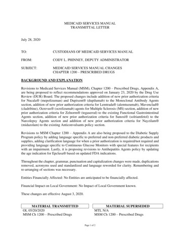
300 SERIESPowerhead Assembly1645MPE3E16F7P1417M91881215LETTERS IN DIAGRAM REPRESENT WIRING CONNECTIONS131011RefDescriptionPart NumberQty0Metered Power Head Assy.23003X10011Softener Circuit Boad Assy.23001X10212Encoder20001X12413Front Plate20001X00414Encoder Wheel20001X00715Main Gear21001X12016Power Supply20001X12517Back Plate20001X00518Lower Front Base For Cover20111X00219Motor20016X006110Lower Back Base for Cover20111X003111Valve Cover20111X008112Piston Screw20001X007113ScrewSC10314ScrewSC9215Piston Washer20001X002116Washer Circuit Board20111X014117Screw MotorSC2121Valve Hex Screw20001X0012F19
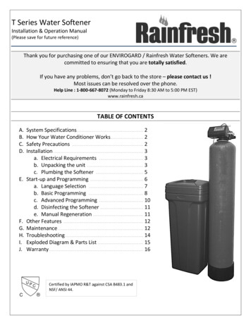
300 SERIESPowerhead Assembly1645MPE3E16F7P1417M91881215LETTERS IN DIAGRAM REPRESENT WIRING CONNECTIONS131011FRef20DescriptionPart NumberQty0Metered Power Head Assy.23003X10011Softener Circuit Boad Assy.23001X10212Encoder20001X12413Front Plate20001X00414Encoder Wheel20001X00715Main Gear21001X12016Power Supply20001X12517Back Plate20001X00518Lower Front Base For Cover20111X00219Motor20016X006110Lower Back Base for Cover20111X003111Valve Cover20111X008112Piston Screw20001X007113ScrewSC10314ScrewSC9215Piston Washer20001X002116Washer Circuit Board20111X014117Screw MotorSC2121Valve Hex Screw20001X0012
300 SERIESValve Body Assy.2121/227394656A1011201312814151617191821
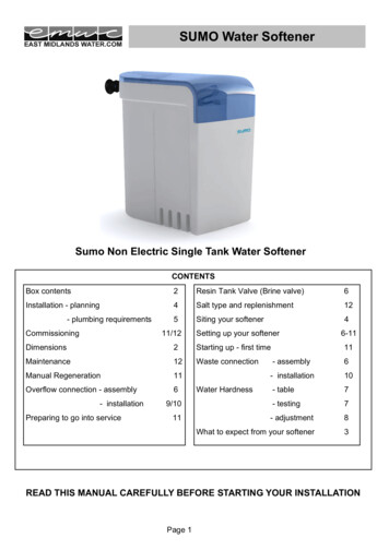
300 Valve Body Assy. Parts ListDescriptionPiston Assembly10-24 X 13/16 Hex HeadSeal and Spacer KitBottom SpacerDLFC 1.5 ButtonDLFC 2.0 ButtonFlow Control Assembly 1.5Flow Control Assembly 2.0Drain Line Flow Control HousingDrain Line Hose Barb, StraightDLFC ClipBrine ValveBrine Line Flow Control Assy.Brine Line Ferrule10-24 X 1 Hex ScrewInjector CoverInjector SealInjector w/ Check BallInjector ScreenInjector PlugTank O-RingDistributor Pilot O-RingFlow MeterValve CompletePart 420017X203VH1-B-D15151111111111112111111111
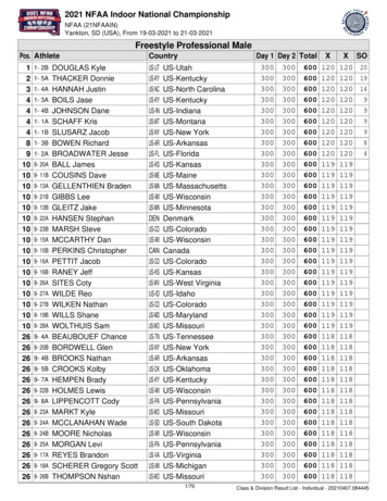
300 SERIESBypass AssemblyRef12345a5bDescriptionD15 Bypass1” Female Straight Slip Set1” NPT Elbow Set1” NPT Straight SetElbow, Vertical Adapter BlankElbow, Vertical Adapter 1/4” NPT TappedPart 8320017X28820017X28420017X
117 Vortech 164 148 Vortech Maximum Raw Water Hardness (grains) 50 75 100 100 100 Maximum Clear Iron/Manganese (ppm) 3 5 5 5 5 Cation Exchange resin (cu. ft.) 0.75 1 1.5 2 3 . The water softener provides a Regeneration process whereby brine solution enters the mineral tank, .