Transcription
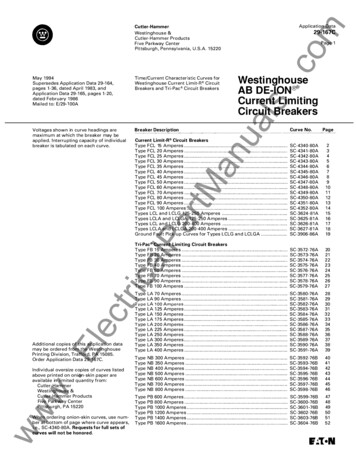
AC High-Voltage Circuit BreakersEverything you wanted to know about ac highvoltage circuit breakers but were afraid to askIEEE Switchgear CommitteePortland (Maine, USA), October 2017Denis DufournetIEEE FellowConsultantSathonay-Camp (France)
40 Years of Experience in HV Circuit 9772015 - 2017
Content1. AC High-Voltage Circuit Breaker2. SF6 and Alternatives3. Rated Characteristics4. Operating Mechanism5. Arcing Phenomena in HV Circuit Breakers6. Arc Extinction Principles7. Switching Duties8. Standards Related to High-Voltage Circuit Breakers9. AnnexesAnnex 1 on TRVAnnex 2 on New Test Procedure T100aAnnex 3 on Transformer Limited Faults
Content1. AC High-Voltage Circuit Breaker2. SF6 and Alternatives3. Rated Characteristics4. Operating Mechanism5. Arcing Phenomena in HV Circuit Breakers6. Arc Extinction Principles7. Switching Duties8. Standards Related to High-Voltage Circuit Breakers9. AnnexesAnnex 1 on TRVAnnex 2 on New Test Procedure T100aAnnex 3 on Transformer Limited Faults
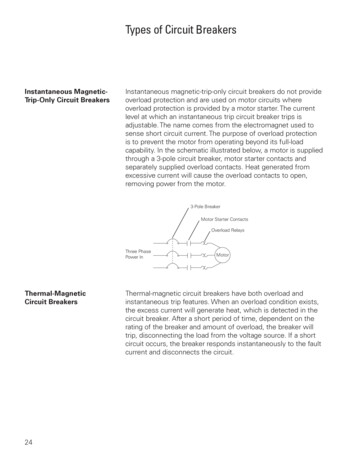
High-Voltage Circuit BreakerDefinitionA mechanical switching device, capable of making, carrying and breaking currents under normal circuit conditionsand making, carrying for a specified time and breaking currents underspecified abnormal circuit conditions such as those of short-circuit.
High-Voltage Circuit BreakerThe main task of a circuit breaker is to interrupt fault currents and toisolate faulted parts of the system.A circuit breaker must also be able to interrupt a wide variety of othercurrents at system voltage such as capacitive currents, small inductivecurrents, and load currents.The following is required from a circuit breaker: In the closed position it must be a good conductor; In the open position it must behave as a good isolator between systemparts; It must be able to change from the closed to open position in a veryshort period of time (typically in less than 0.1 second); It does not cause overvoltages during switching; It is reliable in its operation.
HV Circuit Breaker - TypeAIS SF6 Circuit BreakerAIS: Air Insulated SwitchgearAIS interrupting chamber has- Internal voltage withstand in SF6- External voltage withstand in airInterrupting chamberin open positionInsulator
HV Circuit Breaker - TypeAIS SF6 Circuit BreakerExample of Medium Voltage Circuit breaker
HV Circuit Breaker - TypeAIS SF6 Circuit BreakerExamples of HV circuit breakeroperated single-phaseA: Interrupting chamberB: Insulating columnC: Upper mechanismD: Tripping springE: Closing springF: Control cabinetG: SF6 monitoringH: Lower mechanismL: RodThese circuit breakers are alsocalled LIVE TANK as the chambersare at system potential.
HV Circuit Breaker - TypeAIS SF6 Circuit BreakerExample of HV circuit breakeroperated three-phaseA: Interrupting chamberB: FrameC: Rotating rodD: Tripping springE: Closing springF: Control cabinetG: SF6 monitoringFXT9Ur 72.5 kVIsc 25 kA
HV Circuit Breaker - TypeAIS SF6 Circuit BreakerFX 800 kV 50 kA4 chambers in series per poleModular range with verticalunits (one mechanism perchamber)Closing resistorsGrading capacitors
HV Circuit Breaker - TypeAIS SF6 Circuit BreakerInterrupting chambersInsulating columnOperating mechanism(one operates twochambers)800 kV Circuit-breaker in Russia
HV Circuit Breakers - TypeAIS HV SF6 Circuit BreakersExample of circuit breaker range800KV2XGL317(D) GL318(D)245 kVGL314300 kV362 kVGL315(D)420 kVGL316(D)550 kVGL317(D)
HV Circuit Breaker - TypeAIS SF6 Circuit BreakerCircuit breaker with several chambers in series per pole Open circuit-breaker: voltage distribution is done by– Grading capacitors, or– RingsColors illustrate the voltage distribution calculated by 3D simulation
HV Circuit Breaker - TypeGIS Circuit BreakerGIS: Gas Insulated SwitchgearVoltage withstand ofthe interruptingchamber (betweencontacts and toground) is fully in SF61: Circuit breakerinterrupting chamber2 Circuit breaker operatingmechanism
HV Circuit Breaker - TypeGIS Circuit BreakerGIS 145 kV
HV Circuit Breaker - TypeGIS Circuit BreakerGIS 420 kVInterrupting chambersOperating mechanism
HV Circuit Breaker - TypeGIS Circuit BreakerGIS 420 kV
HV Circuit Breaker - TypeGIS Circuit BreakerSome advantages of GIS reduced size, not sensitive to environmental conditions, safety (active parts are in an enclosure at ground potential), no perturbation to surroundings, good seismic withstand.For voltages 145 kV, the more economical solution is to have the 3poles in the same tank.Higher ratings for a single-break GIS circuit breaker420 kV 63 kA with standard design of spring operated mechanism,550 kV 63 kA with hydraulic mechanism.
HV Circuit Breaker - TypeDead Tank Circuit BreakerDT 245 kV 63 kABushingCurrent transformerInterrupting chamberOperating mechanism
HV Circuit Breaker - TypeDead Tank Circuit BreakerVoltage withstand of theinterrupting chamber(between contacts and toground) is fully in SF6
HV Circuit Breaker - TypeDead Tank Circuit BreakerCircuit breaker with several chambers in series per poleVoltage distribution by grading capacitorsDead Tank Circuit Breaker 550 kVwith grading capacitors
HV Circuit Breaker - TypeHybrid switchgear (Compact switchgear assembly) It is a combination of open-type (AIS) and metal-enclosed equipment(GIS). Hybrid switchgear allows to reduce the size of substations and tocombine the advantages of AIS and GIS. Specific IEC standard: IEC 62271-205. Circuit breaker is of GIS or Dead tank type Depending on the capacitance of the liaison to overhead lines, it isconsidered as a GIS or AIS circuit breaker.In IEC it is considered to be AIS if the capacitance of the liaison between circuit breakerand a line is less than 1.2 nF.
HV Circuit Breaker - TypeExamples of hybrid switchgearCompact switchgear assembly
HV Circuit Breaker - TypeExample of hybrid switchgear (HGIS) 550 kVBushingCircuit breakerDisconnector
HV Circuit Breaker - TypeGenerator Circuit BreakerGenerator circuit breakers are located between a generator and thestep-up transformer.They are generally used withgenerators of high power(100MVA to 1800 MVA) in orderto protect them safely, rapidly andin an economical way.They must be able to carry highcontinuous currents (6300 A to40000 A), and they must have ahigh short-circuit breaking currentcapability (63 kA to 275 kA).
HV Circuit Breaker - TypeGenerator Circuit BreakerCircuit breaker located between a generator and the step-uptransformer.
HV Circuit Breaker - TypeGenerator Circuit BreakerFKG2 17.5 kV 63 kAThree-phase operation byspring mechanismStandard IEC/IEEE 62271-37-013 (2015)
HV Circuit Breaker - TypeGenerator Circuit BreakerFKGA8 Generator Circuit Breaker Isc 210 kA Ur 33 kVSF6 circuit breakerDesigned for Power Plantsfrom 700 to 1,500 MWIt is equipped with aspring-operatedmechanism per pole.30,000 A nominal currentwith natural cooling and upto 40,000 A nominalcurrent with IPB forced aircooling.IPB: Isolated phase bus ducts
HV Circuit Breaker - TypeGenerator circuit breaker with associate equipmentCurrent transformerInterrupting chamberSurge arresterDisconnectorCapacitorEarthing switchVoltage transformerView ports
HV Circuit Breaker – Service ConditionsTemperature in service / SF6 pressureCircuit breakers must function properly in the following normalservice conditions: ambient temperature must not exceed 40 C and the average value,measured during 24h, does not exceed 35 C; minimum ambient temperature is not less than - 25 C according toIEC 62271-1, and - 30 C according to IEEE C37.100.1.Other values of minimum ambient temperature can be specified inparticular cases, such as - 40 C, -50 C in some countries such asCanada or even -60 C in Russia.
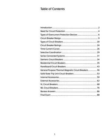
HV Circuit Breaker – Service ConditionsTemperature in service / SF6 pressureDiagram SF6 – Pressure – Density TemperatureConsidering a filling pressure of 7,5 bar (g). at 20 C, liquefaction occurs whentemperature reaches -25 C, the residual gas density corresponds to 6.49 bar (g) at20 C. Partial liquefaction is acceptable for AIS but generally not for GIS.
HV Circuit Breaker – Service ConditionsTemperature in service / SF6 pressurePressure scale The minimum (lock-out) pressure (at 20 C) for insulation and interruptionis defined from the minimal temperature guaranteed.Performances are verified and guaranteed at this minimum pressure. Alarm pressure is 4% higher than the minimum pressure. Filling pressure is approximately 10% higher than the alarm pressure.
HV Circuit Breaker – Service ConditionsTemperature in service / SF6 pressureGas mixture In the case of very low ambient temperatures (e.g. -50 C), it is difficultto obtain the required performances with pure SF6. In these cases gas mixtures can be used with the acceptable pressureof SF6 and the addition of another gas (SF6-CF4, SF6-N2). Another solution is to use heating belts (for Dead tank circuit breakers).
HV Circuit Breaker – Service ConditionsDielectric Strength of SF6 Gas MixturesIn the case of SF6-CF4 and SF6-N2 gas mixtures, voltage withstand asfunction of the percentage of SF6.
Content1. AC High-Voltage Circuit Breaker2. SF6 and Alternatives3. Rated Characteristics4. Operating Mechanism5. Arcing Phenomena in HV Circuit Breakers6. Arc Extinction Principles7. Switching Duties8. Standards Related to High-Voltage Circuit Breakers9. AnnexesAnnex 1 on TRVAnnex 2 on New Test Procedure T100aAnnex 3 on Transformer Limited Faults
Why use SF6 ? Electrical insulationHigh dielectric strength, approx. 2.5 timesthat of air (depending on density) Current breakingHigh electrical arc interrupting capacityapprox. 10 times that of air (depending ondensity) Heat transferTwice better heat transfer than airThese properties make it possibleto significantly reduce the size of electrical equipmentand the operating energy of circuit breakers
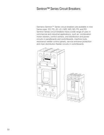
Search for Alternatives to SF61983Boiling point ( C)2014non-toxictoxicvery toxic?Dielectric strength / SF6Source: ETH Zürich, Biasiutti & Zaengl, 1983Search for alternative gases startedalready in the 1980’s
Alternatives to SF6 Vacuum is an alternative for MV applications, but limited to ratedvoltages up to 72.5 kV and possibly 145 kV. For HV applications it was necessary to find an alternative gas or gasmixture. Circuit breakers developed with CO2 (and O2) but limited to 31.5 kA. Grid Solutions alternative called g3 is presented in the next slides. Itcan be used for -25 C applications. Gas mixtures including Fluroketone are also proposed but limited to aminimum temperature of 5 C (e.g. gas mixture with CO2 and O2 for GIS170kV 40kA).
Alternatives to SF6More information to come in
Alternative to SF6 – g3SF6 is main gasfor high voltageinsulation and interruption19381980First experiments on SF6 asquenching medium1997Grid Solutionscooperation with 3M2010SF6 is listed in the Kyotoprotocol as aGreenhouse Gas2014
Alternative to SF6 – g3A new compounddeveloped specifically forswitchgear applicationsfluorinated anenitrileheptafluoroisobutyronitrileCAS # 42532-60-5A gas mixture of3MTM NovecTM compound and CO2
Alternative to SF6 – g3Dielectric withstand is 85 to 100 % that of SF6Dielectric strength increasewhen Novec is added Ratio of Novec molecule in g3depends on vapor pressure atminimum operating temperature For -25 oC, a slight overpressureallows to reach the SF6dielectric strength
Alternative to SF6 – g3Voltage withstandTest duties performed on GIS & AIS products21609CO2/ L-Temperature riseTests on GIS itemsInterruptionTests on 145 kV LT CBSwitchingTests with GISdisconnectors
Alternative to SF6 – g3Drastic reduction of global warming potential98 % lower GWP than SF6SF6380 kg eq. CO223,500 kg eq. CO2Calculation method 100-yr ITHIPCC 2013For 1 kg4 % of 3M Novec
Alternative to SF6 – g3420 kV GIL: Pilot project in UKFirst pilot project with National Grid 300 m GIB at Sellindge substation, in Kent 420 kV, 63 kA, 4000 AGas emissionsduring 40 years(0.5 %/year)Gas emissionsduring 40 years inequivalent carbon(GWP 23500)0.50 tons of SF611750 tons eq. CO2g0.23 tons of g374 tons eq. CO2GIBSF63(GWP 327)Over both g3 busducts:11670 t eq. CO2 will be saved during the operation period
Content1. AC High-Voltage Circuit Breaker2. SF6 and Alternatives3. Rated Characteristics4. Operating Mechanism5. Arcing Phenomena in HV Circuit Breakers6. Arc Extinction Principles7. Switching Duties8. Standards Related to High-Voltage Circuit Breakers9. AnnexesAnnex 1 on TRVAnnex 2 on New Test Procedure T100aAnnex 3 on Transformer Limited Faults
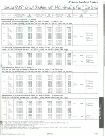
Circuit Breaker Rated Characteristics Rated maximum voltage Rated insulation level* Rated frequency Rated continuous current Rated short-time and peak current Rated short-circuit making and breaking current Rated operating sequenceThe common ratings of switchgear are assigned by the manufacturer.They reflect the common specifications of the switchgear that arespecified by the user and are necessary for operation on the user’snetwork.* In IEEE C37.100.1, but Rated dielectric withstand capabilities in IEEE C37.04
Rated Characteristics / Rated Maximum VoltageThe rated maximum voltage indicates the upper limit of the highestvoltage of systems for which the circuit breaker is intended.Rated values have been generally harmonized between IEC andANSI/IEEE- Medium voltage3,6 – 4.76* – 7.2 – 8.25* – 12 – 15* – 15.5* – 17.5 – 24 – 25.8* – 27*36 – 38* – 48.3* – 52 kV.* : values used in North America (15.5 and 27 kV are preferred to 15 and 25.8 kV)- High voltage72.5 – 100** – 123 – 145 – 170 – 245 – 300** – 362 – 420** – 550 –800 – 1100** – 1200** kV.** : values in IEC onlyIEEE values are given in 6.1 of IEEE C37.04-201x
Rated Characteristics / Insulation LevelThe insulation level/dielectric withstand capability is given by the withstand voltage at power frequency (50 Hz or 60 Hz), the lightning impulse withstand voltage, the switching impulse withstand voltage (Ur 362 kV).These values characterize the dielectric stresses that the circuit breakermust withstand with a very high probability of success.IEEE values are given in 5.3 of IEEE C37.100.1-201xand 6.1 of IEEE C37.04-201x
Rated Characteristics / Insulation Level.Origin of aswitchingimpulseABVoltage at line end BClosing operation by circuit-breaker (A) can produce an overvoltage(switching impulse) on circuit-breaker (B)
Rated Characteristics / Insulation Level.Lightning impulse voltage1.2 µs50 µs2500 µsSwitching impulse voltage250 µsA lightning impulse voltage rises faster than a switching impulse
Rated Characteristics / Insulation LevelInsulation levels in IEEE C37.100.1 for rated voltages 245 kVIEEE C37.100.1 is the IEEEStandardofCommonRequirements for HighVoltage Power SwitchgearRated Above 1000 V
Rated Characteristics / Insulation LevelInsulation levels in IEEE C37.100.1 for rated voltages 245 kVNotes to Table 1
Rated Characteristics / Insulation LevelInsulation levels in IEEE C37.100.1 for rated voltages 245 kV
Rated Characteristics / Insulation LevelPower Frequency Tests for Ur 245 kVExplanation for standard value of 460 kV specified for wet testSwitching surge of 3 p.u. on one terminal: 3 x 245 2 / 3 600 kVEquivalent power frequency value: 600 x 0.75 / 2 318 kVPower frequency voltage on opposite terminal: 245 / 3 141 kVPower frequency voltage between terminals: 318 141 460 kVPower Frequency Tests for Ur 145 kVExplanation for standard value of 275 kV specified for wet testSwitching surge of 3 p.u. on one terminal: 3 x 145 2 / 3 355 kVEquivalent power frequency value: 355 x 0.75 / 2 188 kVPower frequency voltage on opposite terminal: 145 / 3 84 kVPower frequency voltage between terminals: 188 84 272 kV 275 kV
Rated Characteristics / Insulation LevelInsulation levels in IEEE C37.100.1 for rated voltages 362 kV* Values for combined test with switching impulse voltage applied on oneterminal and power frequency voltage applied on the other terminal.
Rated Characteristics / Insulation LevelInsulation levels in IEEE C37.100.1 for rated voltages 362 kV* Values for combined tests
Rated Characteristics / Insulation LevelValues in the draft revision of IEEE C37.04, coming from IEEE C37.06 (2009)Should be 1175In accordance with the standard test procedure of IEEE Std 4, the duration of the wet testshould be 1 min. As explained in this presentation, some power frequency values for drytests (Ur 123 kV, 145 kV & 170 kV) in Col 3 should be corrected (values in IEEE C37.122).
Rated Characteristics / Insulation LevelPower frequency test voltage in IEEE C37.06 for Ur 121 kV With two exceptions (Ur 170 kV and 362 kV), the power frequency testvoltage Ud is approximately 0.472 times the BIL for dry conditions.for exampleUr 121 kVBIL 550 kVUd 0.472 x 550 260 kVUr 145 kVBIL 650 kVUd 0.477 x 650 310 kVUr 245 kVBIL 900 kVUd 0.472 x 900 425 kVUr 550 kVBIL 1800 kVUd 0.478 x 1800 860 kVUr 800 kVBIL 2050 kVUd 0.468 x 1800 960 kV The Ud value for Ur 362 kV is 555 kV. It is based on a BIL of 1175 kV andwas not changed when BIL was raised to 1300 kV. Experience in serviceconfirmed that 555 kV can be kept, suggesting that the factor 0.472 is toohigh and should be reduced*. IEC values are based on a factor 0.43 (e.g. Ud 275 kV for Ur 145kV) Some IEC values having a different basis can be higher e.g. for Ur 245 kV& BIL 1050 kV: Ud 460 kV.* See IEEE Tutorial Course ″Application of power circuit breakers, - Insulation Considerations for ACHigh Voltage Circuit Breakers″, by C.L.Wagner & R.A.York (1995).
Rated Characteristics / Insulation LevelValues for circuit breakers in the draft revision of IEEE C37.04From IEEE C37.06, a voltage withstand is specified with lightningimpulse chopped waves, chopped at 2 µs, but not for GIS circuitbreakers.In practice it corresponds to the (rare) case of a second component ofa lightning stroke with the circuit already opened, therefore notprotected by the bus side surge arrester*.As the surge voltage appliedis often faster than thestandard impulse wave, ahigher peak value is specified:1.29 times the lightningimpulse withstand voltagevalue.* Full explanation in IEEE Tutorial Course ″Application of power circuit breakers, - InsulationConsiderations for AC High Voltage Circuit Breakers″, by C.L.Wagner & R.A.York (1995).
Rated Characteristics / Insulation LevelIEEE insulation levels: values for circuit breakers in GIS substationsabove 52 kV are given in IEEE C37.122-2011Note: Ud 275 kVfor circuit breakerswith Ur 145kV
Rated Characteristics / Insulation LevelDielectric tests are done to verify the insulation level.The dielectric withstand must be verified in the following cases: withstand between terminals, circuit breaker open withstand to ground, circuit breaker open withstand to ground, apparatus closed.In all cases the aim is to verify the withstand of each pole and, whenapplicable, the withstand between poles.Tests on switchgear filled with gas are done with the minimum gaspressure.
Rated Characteristics / Insulation LevelPower frequency withstand voltage tests These tests are required for all rated voltages. These tests are the only one performed as routine (production) tests. Tests values are defined to be equivalent to those for impulse tests. According to IEC, the withstand during 1 minute in dry and in wet conditionsis required.No disruptive discharge is allowed during the dry test.The test in wet condition can be repeated if there is a disruptive discharge,but no other discharge is allowed. ANSI/IEEE has a similar procedure, with the exception of wet tests that havea duration of 10 seconds and the flow rate of rain is higher (5 mm/min). IEEE Std 4 (2013) has a new standard procedure with a precipitation rate (1to 2 mm/min vertically and horizontally) and a duration of 60 s as in IEC. IEEE C37.09 should make reference to this new procedure of IEEE Std 4.
Rated Characteristics / Insulation LevelLightning impulse withstand voltage tests These tests are required for all rated voltages. They are performed only withdry conditions. According to IEC, a series of 15 impulses is done for each test configurationand for each polarity of voltage; only 3 impulses according to IEEE, plus 9 ifthere is a disruptive discharge. IEC: for rated voltages higher than 245 kV, combined tests are required in openposition with lightning impulse voltage applied on one terminal and powerfrequency voltage applied on the other terminal.Tests also given in Table 4 of IEEE C37.100.1 IEC: tests are successful if the following conditions are met:– number of disruptive discharges does not exceed 2 in each series;– no disruptive discharge must occur on non self-restoring insulation (This isconfirmed by 5 consecutive impulse withstands following the last disruptivedischarge).
Rated Characteristics / Insulation LevelSwitching impulse withstand voltage tests These tests are required for rated voltages higher than 245 kV. There are done in dry and wet conditions, with both polarities of voltage. According to IEC, a series of 15 impulses is applied for each configuration; only3 impulses according to ANSI/IEEE plus 9 if there is a disruptive discharge.The circuit breaker being in closed and open position, the test voltage is appliedwith the rated switching impulse voltage withstand to ground specified. According to IEC: a second series of tests must be done with a switchingimpulse voltage applied on one terminal and a power frequency voltage appliedon the other terminal.Tests are also given in Table 4 of IEEE C37.100.1 The criteria to pass the tests is the same as for lightning impulse voltage tests.
Rated Characteristics / Insulation LevelInternal insulation Gas with good dielectric properties (e.g. SF6) or vacuum. Good dimensioning of distances, metallic and insulating parts Avoid internal pollution or reduce it (during operations)External insulation Insulators in porcelain or composite ofappropriate length. Withstand in wet or polluted conditions,obtained by an appropriate choice of sheds(to have the required creepage distance)
Rated Characteristics / Rated FrequencyThe. rated values for HV switchgear are 50 Hz and 60 Hz.Other values are possible, for example 16 2/3 Hz and 25 Hz for railwaysapplications.
Rated Characteristics / Rated FrequencyApplications at 16.6 Hz and 25 Hz These applications mayrequire special types ption are different fromthose at 50Hz or 60Hz, andmay be more severe.F 16,6 HzF 50 HzF 60 Hz00,0050,010,0150,020,0250,030,035
Rated Characteristics / Continuous CurrentThe rated continuous (normal) current is the current that the circuit breakercan carry permanently under normal conditions of service.When carrying the current, the temperature of parts rise but must not exceedvalues defined in the standards. These values are defined to ensure that thecharacteristics of materials will be kept.Limits of temperature and temperature rise are given in IEC 62271-1 andIEEE C37.100.1.Rated values defined in IEC are as follows:630 - 800 - 1250 - 1600 - 2000 - 2500 - 3150 - 4000 - 5000 - 6300 AThese values are based on the R10 series of Renard with values proportionalto 10 n/10.The present draft revision of IEEE C37.04 gives the following values ofcurrents (taken from C37.06): 600 -1200 - 1600 - 2000 - 3000 - 4000 - 5000 AIEEE C37.100.1 states that values should be selected from the R10 series.Note 2 indicates that relevant equipment standards may specify orgrandfather other traditional values, e.g. 600 A, 900 A and 1200 A.
Rated Characteristics / Continuous CurrentRenard’s Series R10n12345678910n/100,10,20,30,40,50,60,70,80,91A 7,94310,0001000 A12591585199525123162398150126310794310000In 615,820,025,131,639,850,163,179,4100,0Isc (kA)12,516202531,540506380100French engineer,inventor andballoonist CharlesRenard (1847-1905)Renard’s series were adopted by ISO in 1952, and later by IEC.For GIS 52 kV, IEEE C37.122 indicates that IEEE C37.100.1 applies(i.e. values in R10 series).
Rated Characteristics / Continuous Current.Closed positioncurrent passesthrough the maincontactsAfter maincontactsseparationcurrent passesthough arcingcontactsAfter arcingcontactsseparationcurrent carried byan arc betweenarcing contactsOpen positioncurrent isinterrupted
Rated Characteristics / Continuous Current.Moving arcing contact(tulip)Stationary main andarcing contacts
Rated Characteristics / Rated Short-timeWithstand Current and Peak Withstand CurrentThey are the currents that a circuit breaker must withstand in closedposition: a short-circuit current (r.m.s.) during a given time (1 s, 2 s or 3 s) ; a peak current that it can withstand.When a short-circuit occurs at a zero voltage, the current is said to beasymmetrical. It has a high peak that a circuit breaker must withstand.The asymmetrical current is the sum of a periodical (a.c.) componentand a d.c. component that is decreasing towards zero with a timeconstant that is function of the network characteristics.Ratings are given in 5.6 and 5.7 of IEEE C37.100.1Tests are called STC in Table 1 of IEEE C37.09-201x
Rated Characteristics / Rated Short-timeWithstand Current and Peak Withstand CurrentExample of situation where a circuit-breaker 2 needs a short-time andpeak withstand current capabilitySupplyCircuit Breaker 1Circuit Breaker 2(closed)LineFault
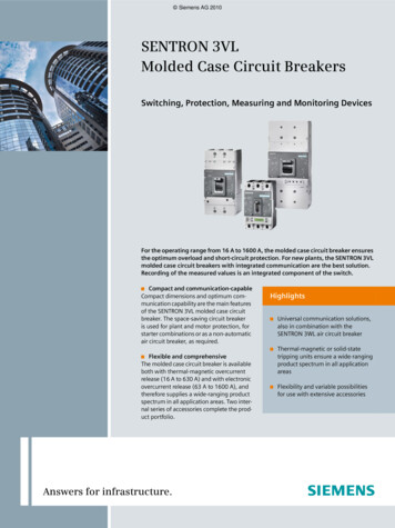
Rated Characteristics / Rated Peak WithstandCurrentETABLISSEMENTCOURANT SYMETRIQUESymmetricalCurrent / MAKINGSYMMETRICAL CURRENTUIsym147 10 13 16 19 22 25 28 31 34 37 40 43 46 49 52 55 58 61 64 67T (ms)When the fault occurs at maximal voltage, the short-circuit current issymmetrical
Rated Characteristics / Rated Peak WithstandCurrentAsymmetrical CurrentUIasym147 10 13 16 19 22 25 28 31 34 37 40 43 46 49 52 55 58 61 64 67T (ms)When the fault occurs at zero voltage, the short-circuit current is asymmetrical
Rated Characteristics / Rated Peak WithstandCurrentAsymmetrical current2D.C. component1,510,5000,010,020,030,040,05-0,5-1A.C. component-1,50,060,070,08
Rated Characteristics / Rated Peak WithstandCurrentThe peak value of the short-time withstand current is equal to the productof the rated short-circuit current by the following factor2.5for rated frequency 50Hz2.5 1.80 22.6for rated frequency 60Hz2.6 1.83 22.7for special applications (time constant 45 ms)For example the peak current corresponding to 40 kA in a 60Hz networkis 2.6 x 40 104 kA.
Rated Characteristics / Rated Peak WithstandCurrentSimulation Iasym in case L/R 45 ms & fr 60 HzAt 60 Hz, the peak value is 1.83 times the peak symmetrical currentThe peak factor is then 1.83 2 2.6
Rated Characteristics / Rated Short-Circuit Making& Breaking CurrentRated Short-Circuit Breaking CurrentThe rated short-circuit breaking current is the highest current that thecircuit-breaker shall be capable of breaking under conditions of use andbehaviour prescribed in the standard.Rated Short-Circuit Making CurrentThe short-circuit making current is the product of the r.m.s. value of thea.c. component of its rated short-circuit breaking current by the factor 2.5 for rated frequency 50Hz 2.6 for rated frequency 60Hz 2.7 for special applications (time constant 45 ms)Ratings in 5.5 of IEEE C37.04-201x
Rated Characteristics / Operating SequenceO - t - CO - t' – COwith t' 3 min. t 3 min for circuit-breakers not intended for rapid auto-reclosing; t 0.3 s, for circuit-breakers intended for rapid auto-reclosing;CO - t"- CO Orepresents an opening operation; CO represents a closing operation followed immediately by anopening operation. t" is 30 min for a generator circuit breakerRatings in 5.9 of IEEE C37.04-201x
Rated CharacteristicsMechanical endurance Two classes are defined in IEC for mechanical endurance Class M1 for normal mechanical endurance: 2000 CO Class M2 for extended mechanical endurance: 10 000 COOperating sequenceSupply voltage andoperating pressureNumber of operating sequencesCircuit-breakers forauto-reclosingC-ta -O-taO-t-CO-t a-C-t aCO-taCircuit-breakers mRated500250500--500RatedIEC tests for class M1 circuit breakers: 2000 C and 2000 O
Other CharacteristicsBreak Time / Interrupting TimeClosed positionContactsmotionOpen positionCurrentflow timeOpeningTimeArcing timeBreak timeInitiation ofopening operationContacts separatedin all polesCurrent interruptedin all poles
Other CharacteristicsBreak Time / Interrupting TimeIEC The break time (or interrupting time) is no longer a rating in IEC62271-100. It is a value that can be derived from tests, but not tested as a ratingbecause breaking tests are performed at minimum values of pressureand control voltage (not at rated values). The method to calculate the break time is given in IEC/TR 62271-306.IEEE The interrupting time (or break time) is a rating in IEEE C37.04“Standard Ratings and Requirements for AC HV Circuit Breakers” The method of calculation given in the draft revision of IEEE C37.09“Test Procedures for AC HV Circuit Breakers” is the same as in IEC.Interrupting time tests in 4.7 of IEEE C37.09-201x
Other CharacteristicsSimultaneity of Operation Simultaneity of poles and interrupting chambers– Open operation Less than 1/6 cycle between poles (IEC and IEEE) Less than 1/8 cycle between chambers of same pole (IEC)– Closing operation Less than 1/4 cycle between poles (IEC and IEEE) Less than 1/6 cycle between chambers of same pole (IEC)1/8 cycle at 60 Hz is 1/60 x 1/8 x 1000 2.1 ms1/6
Portland (Maine, USA), October 2017. 1980 1985 1989 1991 1998 2004 2010 GRID SOLUTIONS 40 Years of Experience in HV Circuit Breakers 1977 2015 - 2017. Content 1. AC High-Voltage Circuit Breaker 2. SF 6 and Alternatives 3. Rated Characteristics 4. Operating Mechanism 5. Arcing Phenomena in HV Circuit Breakers 6. Arc Extinction Principles