Transcription
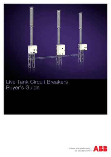
Live Tank Circuit BreakersBuyer’s Guide
Table of e Insulators134Puffer, Auto-Puffer 22Controlled Switching136On-line Monitoring System142Design features and advantages:Optional for special applications:LTB circuit breaker family26Cable entry kits - Roxtec145HPL circuit breaker family30Seismic withstand capability146BLK operating mechanism33Quality control and testing148BLG operating mechanism38Inquiry data150FSA1 operating mechanism42MSD operating mechanism47MD Motor Drive operating mechanism52Technical cataloguesLTB circuit breaker family58HPL circuit breaker family81BLK operating mechanism95BLG operating mechanism103FSA1 operating mechanism111MSD operating mechanism121MD Motor Drive operating mechanism1262 Product information Live Tank Circuit Breakers — Buyer’s Guide
ABB is the supplier of cutting edgetechnologyOur task is to help our customers to a more reliablepower grid and sustainable society at large. This is whywe always strive for the leading position in researchand development. ABB has all the experience necessaryfor successful development of power transmissiontechnology.This Buyer’s Guide concerns one of our true specialty areas– high voltage circuit breakers – an area in which we are constantly striving to improve product performance that deliversreal customer value. What has pushed development forwardhas been the capability to increase availability at our customers’ installations by supplying reliable high voltage equipment.Development is a team effortOur development team consists of highly qualified and experienced technicians with expert knowledge in, for example,plasma physics, materials physics, gas dynamics, mechanicsand high voltage technology. We also collaborate with otherswith expert knowledge and skills, both at ABB and externally.An important aspect of development work is our close dialogwith customers, which enables us to find out about their experiences. Customers who demand more of our products giveus the best platforms to realize new innovations.Thought leadershipOur design work with constant improvements and simplification of our products have resulted in; 550 kV circuit breakerswithout grading capacitors; the Motor Drive with a servo motor system that accurately controls and monitors the contactoperation and the LTB D1 and E1 circuit breakers with MSDoperating mechanism that provide fast and simple installationat site.Other mile stones: 80 kA with only two breaking chambers per pole The DCB concept that enables smarter, safer and greenersubstations Excellent earthquake performance suitable for seismicregions The eco-efficient CO2 circuit breaker LTANew technology requires careful testing.ABB’s high power laboratory is among the world’s most modern and best equipped labs for switchgear technology, with facilities for testing circuitbreakers with rated voltages of up to 1200 kV and breaking currents of up to 80 kA.Live Tank Circuit Breakers — Buyer’s Guide Product information 3
Product portfolioLive Tank Circuit BreakersABB has a complete portfolio and well proven technology for high voltage circuit breakers used in a number ofapplications.LTB D1 72.5 – 170LTB E1 72.5 – 245LTB E2 362 – 550LTB E4 800IEC, IEEEIEC, IEEEIEC, IEEEIEC, IEEERated voltage72.5 – 170 kV72.5 – 245 kV362 – 550 kV800 kVRated currentup to 3150 Aup to 4000 Aup to 4000 Aup to 4000 AStandardsCircuit-breaking capacityup to 40 kAup to 50 kAup to 50 kAup to 50 kAAmbient temperature-30 – 40 ºC-30 – 40 ºC-30 – 40 ºC-30 – 40 ºCThe circuit breakers can also be supplied for ambient temperatures down to -60 or up to 70 ºC.ONONONHPL 72.5 – 300HPL 362 – 550HPL 800IEC, IEEEIEC, IEEEIEC, IEEERated voltage72.5 – 300 kV362 – 550 kV800 kV *)Rated currentup to 4000 AStandardsup to 4000 Aup to 4000 ACircuit-breaking capacityup to 80 kAup to 80 kAup to 80 kAAmbient temperature-30 – 40 ºC-30 – 40 ºC-30 – 40 ºC*) Up to 1200 kV on requestThe circuit breakers can also be supplied for ambient temperatures down to -60 or up to 70 ºC.4 Product information Live Tank Circuit Breakers — Buyer’s Guide
Product portfolioDisconnecting Circuit BreakersAs a complement to the basic versions of our circuit breakers, which are primarily designed for conventionalsubstation solutions, there is a disconnecting circuit breaker configuration with the disconnecting function integratedinto the breaking chamber. A safe interlocking system, composite insulators and a motor-driven grounding switchprovide personal safety.DCB LTB 72.5DCB LTB 145DCB HPL 170-300IECIECIECIECRated voltage72.5 kV145 kV170 - 300 kV362 - 550 kVRated currentup to 4000 AStandardsDCB 362-550up to 3150 Aup to 3150 Aup to 4000 ACircuit-breaking capacityup to 40 kAup to 40 kAup to 50 kAup to 63 kAAmbient temperature-30 – 40 ºC-30 – 40 ºC-30 – 40 ºC-30 – 40 ºCThe disconnecting circuit breakers can also be supplied for other data on request.For more information about DCBs, please see Application Guide 1HSM 9543 23-03enLive Tank Circuit Breakers — Buyer’s Guide Product information 5
Installations withABB Live Tank Circuit BreakersLTB 420 E2 with current transformer IMB. Installation in Denmark.Substation in Oman with dessert climate. ABB equipment with LTB 145.Disconnecting circuit breaker LTB DCB for 72.5 kV installed at a windfarmin Sweden.Disconnecting circuit breaker HPL DCB for 420 kV installed in a switchingstation in Sweden.Disconnecting circuit breaker LTB DCB for 145 kV with the operatingmechanism Motor Drive installed at refurbishment in Norway.1100 kV by-pass switch in series compensation installation in China.6 Product information Live Tank Circuit Breakers — Buyer’s Guide
Exceeding Customer Expectations —ABB Live Tank Circuit BreakersABB has over a century of experience in developing,testing and manufacturing high voltage circuit breakers.Through the years, our circuit breakers have acquired areputation for high reliability and long life in all climatesand in all parts of the world.Product rangeTypeOur apparatus are manufactured in a workshop where wecontinuously are working with improvements regardingquality, work environment, environment and safety.Maximum ratedMaximum ratedMaximum ratedvoltagecurrentbreaking current(kV)(A)(kA)Circuit Breaker LTBLTB D1/B170315040SF 6 Auto-Puffer interrupter designLTB E1245400050Spring or Motor Drive operatingLTB E2550400050mechanism(s)LTB E4800400050Circuit Breaker HPLHPL B1300500080SF 6 puffer interrupter designHPL B2550500080Spring operating mechanism(s)HPL B4800 * )400080Controlled SwitchingSwitchsync Condition MonitoringOLM2*) Up to 1200 kV on requestOther data and/or special applications not covered in this Buyer’s Guide will be quoted on request.How to interpret the type designationsThe circuit breaker type designations are for simplicity reasons not always given in full in this document.The product portfolio basically consists of three productgroups:Other informationsFor information about Compact air insulated HV switchgearsolutions with Disconnecting Circuit Breaker, please see separate Application Guide.Catalogue publication 1HSM 9543 23-03 en. LTB xxxD1/B (a single-unit circuit breaker) LTB xxxEy (a single-, two- or four-unit circuit breaker) HPL xxxBy (a single-, two- or four-unit circuit breaker)Further information about controlled switching applications andSwitchsync controllers is found in Controlled Switching,Buyer’s Guide/Application Guide.Catalogue publication 1HSM 9543 22-01en.Circuit breakers of type LTB are SF6 gas circuit breaker ofself-blast design while circuits-breakers of type HPL are SF6puffer circuit breakers.In the full type designation xxx indicates the rated voltageand y indicates number of series connected breaking unitsper pole. In this document where the circuit breakers aredescribed in general the voltage designations as well as thenumber of series connected breaking units are omitted.Information about the new CO2 insulated high voltage circuit breakerLTA is found in brochure 1HSM 9543 21-06enLive Tank Circuit Breakers — Buyer’s Guide Product information 7
ExplanationsTechnical specifications - GeneralStandard/Customer specificationThere are international and national standards, as well as customer specifications. ABB High Voltage Products can meet mostrequirements, as long as we are aware of them. When in doubt,please enclose a copy of your specifications with the inquiry.TestsType tests (design tests) and routine tests (production tests)are required by standards.- Type testsType tests are performed only once on one representative testobject in accordance with applicable standards and are notrepeated without extra charge. The purpose of the type testsis to verify the ratings of the design.- Routine testsBefore delivery routine tests are performed in accordance withapplicable standards on each circuit breaker. The purpose ofthe routine tests is to verify the assembly and the function onevery individual circuit breaker. Routine test certificates aresent to the user with each delivery.Extended routine tests exceeding requirements by standardswill be charged extra.Please see special chapter Quality Control and Testing.Rated voltageThe rated voltage is the maximum voltage (phase-phase),expressed in kV rms, of the system for which the equipment isintended. It is also known as maximum system voltage.Rated insulation levelThe combination of voltage values which characterizes theinsulation of a circuit breaker with regard to its capability towithstand dielectric stresses.The rated value given is valid for altitudes 1000 m above sealevel. A correction factor is introduced for higher altitudes.The definition “Across isolating distance” is only applicable fordisconnectors and disconnecting circuit breakers.The rated Lightning Impulse Withstand Level (LIWL) indicatesthe required withstand level phase-to-earth (phase-to-ground),between phases and across open contacts.The value is expressed in kV as a peak value.For voltages 300 kV two values are stated by IEC, a LIWLvoltage on one of the main terminals and power frequencyvoltage on the other.Example 420 kV: 1425 ( 240) kV.Alternatively a LIWL pulse with the sum of the two voltages(1665 kV) can be applied on one terminal, while the other isgrounded.BIL (Basic Insulating Level) is an old expression but means thesame as LIWL.Rated Full Wave is often used in older ANSI/IEEE standardsbut means the same as LIWL.Rated Power Frequency Withstand VoltageThis test is to show that the apparatus can withstand thepower frequency over-voltages that can occur.The Rated Power Frequency Withstand voltage indicates therequired withstand voltage phase-to-earth (phase-to-ground),between phases and across open contacts. The value isexpressed in kV rms.Rated SIWLFor voltages 300 kV the power-frequency voltage test ispartly replaced by the switching impulse test. The wave shape250/2500 µs simulates switching over-voltage.The rated Switching Impulse Withstand Level (SIWL) indicatesthe required withstand level phase-to-earth (phase-to-ground),between phases and across open contacts. The value isexpressed in kV as a peak value. The switching impulse isrequired only for voltages 300 kV. Two values are stated byIEC, a SIWL voltage on one of the main terminals and powerfrequency voltage on the other.Example 420 kV: 900 ( 345) kV.Rated LIWLThe lightning impulse test is performed with a standardizedwave shape 1.2/50 µs for simulation of lightning over-voltage.8 Product information Live Tank Circuit Breakers — Buyer’s GuideAlternatively a SIWL pulse with the sum of the two voltages(1245 kV) can be applied on one terminal, while the other isgrounded.
Rated Chopped Wave Impulse Withstand voltagePhase-to-earth and Across open gapThe rated chopped wave impulse withstand level at 2 μsand 3 μs respectively, indicates the required withstand levelphase-to-earth (phase-to-ground) and across open contacts.The chopped wave impulse is only referred to in IEEE standards and hence, not applicable for IEC.Rated frequencyThe rated (power) frequency is the nominal frequency of thesystem expressed in Hz, which the circuit breaker is designedto operate in.Standard frequencies are 50 Hz and 60 Hz.Other frequencies, such as 16 2/3 Hz and 25 Hz might beapplicable for some railway applications.Rated normal currentThe rated normal current (sometimes referred to as rated current, nominal current or rated continuous current) is the maximum continuous current the equipment is allowed to carry.The current is expressed in A rms.The rated normal current is based on a maximum ambient temperature of 40 C. At higher temperatures derating of the normalcurrent might be necessary.Rated short-time withstand currentThe rated short-time withstand current is the maximum current (expressed in kA rms) which the equipment shall be ableto carry in closed position for a specified time duration. Therated short-time withstand current is equal to the rated shortcircuit breaking current.Standard values for duration are 1 or 3 s.Rated peak withstand currentThe peak withstand current is the peak value of the first majorloop (expressed in kA) during a short-time withstand currentthat the equipment shall be able to carry.The peak value is related to the rms value, frequency and timeconstant (τ ). Specified values are:- 2.5 x rated short-time withstand current at 50 Hz at τ 45 ms- 2.6 x rated short-time withstand current at 60 Hz at τ 45 ms- 2.7 x rated short-time withstand current at 50/60 Hz at τ 45 msRated short-circuit breaking currentThe rated short-circuit (breaking) current is the maximumsymmetrical short-circuit current in kA rms, which a circuitbreaker shall be capable of breaking.Two values are related to the rated short-circuit current: The rms value of the AC component The percentage DC component (depending on the minimum opening time of the circuit breaker and the timeconstant τ)Rated short-circuit making currentThe rated short-circuit making current is the maximum peakcurrent the circuit breaker shall be able to close and latchagainst. This is also referred to in IEEE as closing and latchingcapability.Rated short-circuit making current is equal to Rated peakwithstand current.The peak value is related to the rms value of the rated shortcircuit breaking current, frequency and time constant (τ ).Specified values are:- 2.5 x rated short-time withstand current at 50 Hz at τ 45 ms- 2.6 x rated short-time withstand current at 60 Hz at τ 45 ms- 2.7 x rated short-time withstand current at 50/60 Hz at τ 45 msLive Tank Circuit Breakers — Buyer’s Guide Product information 9
ExplanationsSystem and Switching ConditionsEarthing of the networkThe earthing of the network may vary with region and ratedvoltage.For higher rated voltages, networks tend to have effectivelyearthed neutral. For lower rated voltages, networks usually havenon-effectively earthed neutral (isolated or resonant earthed).Rated out-of-phase making and breaking currentThe rated out-of-phase breaking current is the maximum outof-phase breakingcurrent the circuit breaker shall be capable of breaking.The standard value of the rated out-of-phase breaking currentis 25% of the rated short-circuit breaking current.The type of earthing is an important parameter for defining the transient recovery voltageOut-of-phaseThe power frequency recovery voltage (rms) for out-of-phaseconditions can be calculated as:First-pole-to-clear-factorThe first-pole-to-clear-factor (kpp) is depending on the earthingof the network. The first-pole-to-clear-factor is used for calculating the transient recovery voltage for three-phase faults.The corresponding transient recovery voltage (uc) can becalculated as:In general the following cases apply: kpp 1.3 corresponds to three-phase faults in systems with aneffectively earthed neutral. kpp 1.5 corresponds to three-phase faults in isolatedsystems or resonant earthed systems. kpp 1.0 corresponds to special cases, e.g. two-phaserailway systems, short-line fault.Where:Ur Rated voltage (kV)k pp first-pole-to-clear-factor (out-of-phase) or out-of-phase voltage factork af Amplitude factor (According to IEC: 1.25)Standardized values for the out-of-phase voltage factors are:A special case is when there is a three-phase fault withoutinvolving earth. This case corresponds to kpp 1.5. This caseis covered by the IEEE standards.Rated Transient Recovery VoltageThe rated transient recovery voltage (TRV) is the peak transient voltage (expressed in kV) that corresponds to the firstpole-to-clear when interrupting a three-phase fault at ratedshort-circuit current.The rated transient recovery voltage (uc) is calculated as follows (based on IEC):Where:U r Rated voltage (kV)k pp first-pole-to-clear-factor 2.0 for systems with effectively earthed neutral 2.5 for systems with non-effectively earthed neutralExample:At 245 kV with kpp 2.0, the out-of-phase transient recovery voltagewill be 500 kVThe applied voltage before making is not affected by the earthing of the system. The maximum applied voltage during out-ofphase conditions is always 2.0 times the single-phase voltage.Rated surge impedance and other short-line faultcharacteristicsWhen a short-circuit occurs on an overhead line not far froma circuit breaker, traveling waves will generate a very steepfirst part of the transient recovery voltage. The Rate of Riseof Recovery Voltage, RRRV is depending on the short-circuitcurrent and the surge impedance.k af Amplitude factor (According to IEC: 1.4 at 100% short-circuit current)Example:At 145 kV with kpp 1.5 the rated transient recovery voltagewill be 249 kV10 Product information Live Tank Circuit Breakers — Buyer’s GuideThe surge impedance may vary depending on e.g. type ofconductors.In standards IEC and IEEE, the surge impedance has beenstandardized to a value of 450 Ω.
Other characteristics for the short-line fault are the peak factor and the RRRV factor. These have been standardized to thefollowing values:Example:What is the peak recovery voltage for a 245 kV breaker whenswitching a no-load line with earthed neutral?Peak factor: 1.6RRRV factor: 0.2 (kV/μs)/kA for 50 Hz0.24 (kV/μs)/kA for 60 HzThe voltage factor is 1.2 due to earthed neutral system.Capacitive voltage factorThe capacitive voltage factor is used for defining the singlephase recovery voltage for different capacitive switching applications. The factor is depending on the following:Application No-load line switching No-load cable switching Capacitor bank switchingEarthing of the network Earthed neutral Non-effectively earthed neutral (isolated or resonant earthed)Standard values for capacitive voltage factors for normal service conditions are as follows:No-load line switching: 1.2 (effectively earthed neutral) 1.4 (non-effectively earthed neutral)No-load cable switching: 1.0 (screened cables in systems with solidly earthed neutral) 1.2 (belted cables in systems with effectively earthed neutral) 1.4 (in systems with non-effectively earthed neutral)Capacitor bank switching: 1.0 (capacitor bank with earthed neutral in systems withsolidly earthed neutral) 1.4 (capacitor bank with non-effectively earthed neutral)When different capacitive voltage factors apply from differentapplications, the highest value should be referred to.The voltage factor can be used to calculate the single-phaserecovery voltage peak:The peak recovery voltage is:Capacitive switching classThere are two different capacitive switching classes: Class C1: Circuit breaker with low probability of restrikeduring capacitive switching. Class C2: Circuit breaker with very low probability of restrike during capacitive switching.A circuit breaker intended for Class C2 can of course also beused for Class C1.Rated capacitive inrush current and inrush frequencyThe rated capacitive inrush current (peak value) is only applicable for circuit breakers intended for switching of (mainlyback-to-back) capacitor banks.The inrush current is characterized by a very high inrush current and inrush frequency.Values may vary due to different configurations of capacitorbanks, current limiting inductance etc.Standardized value of inrush current is 20 kA (peak value) andwith an inrush current frequency of 4.25 kHz.Time constantThe time constant of the system is equal to the ratio betweeninductance and resistance in the network (L/R) and is expressed in ms. Standard value is 45 ms. The time constantwill affect the required DC component.There is a relationship between the time constant and theX/R-ratio.If a required X/R-ratio has been given, the time constant in mscan easily be calculated by dividing the X/R-ratio with (2 x π x f),where f is the rated frequency.Where:Ur Rated voltagekcCapacitive voltage factorExample:X/R 14 corresponds to a time constant of 45 ms at 50 HzX/R 17 corresponds to a time constant of 45 ms at 60 HzLive Tank Circuit Breakers — Buyer’s Guide Product information 11
ExplanationsAmbient ConditionsMinimum ambient temperatureThe minimum ambient (air) temperature specifies the lowesttemperature at which the circuit breaker shall be able to operate, at specified ratings.Important standard values are -30 C and -40 CThe minimum ambient temperature affects the choice of gaspressure and/or gas mixture.Maximum ambient temperatureThe maximum ambient (air) temperature specifies the highesttemperature at which the circuit breaker shall be able to operate, at specified ratings.NOTE!Creepage distance voltage used to be phase to phase voltage.To avoid confusion check which voltage reference that is used.Pollution levelEnvironmental conditions, with respect to pollution, are sometimes categorized in pollution levels. The pollution levels aredescribed in IEC 60815. During 2008 the former levels I, II, IIIand IV were replaced with the five levels a, b, c, d, and e.There is a relation between each pollution level and a corresponding minimum nominal specific creepage distance.Since 2008 IEC 60815 states that the phase - ground voltageshall be used for description of creepage distances instead ofphase - phase voltage as in the old versions of the standard.The maximum ambient temperature can affect the continuouscurrent carrying capability.As a reference the old values are also given below.Standard value is 40 C.Pollution levelAltitudeThe external dielectric strength becomes reduced at higher altitudes due to the lower density of air. Standard dielectric typetests are valid for installations up to 1000 masl. For verification of the suitability of installation at higher altitudes the testvoltages has to be corrected.Correction factor according to standard has to be used forexternal insulation. (IEC 62271-1)Creepage distanceThe creepage distance is defined as the shortest distancealong the surface of an insulator between two conductiveparts.Creepage distanceCreepage distance (Old)Phase - Ground voltagePhase - Phase voltagemm/kVmm/kVa - Very light22.0-b - Light27.8(16)c - Medium34.7(20)d - Heavy43.3(25)e - Very Heavy53.7(31)Ice classIf applicable, outdoor switchgear may be assigned to withstand a specified ice coating. Three classes exist in IEC:The required creepage distance is specified by the user in: 1 mm of ice coating 10 mm of ice coating 20 mm of ice coating mm (total creepage distance) mm/kV (creepage distance in relation to the phase toground voltage).Wind loadThe specified wind loads for circuit breakers intended for outdoornormal conditions are based on a wind speed of 34 m/s, (IEC).12 Product information Live Tank Circuit Breakers — Buyer’s Guide
DesignSingle- or three-pole operationFor single-pole operation (1-pole operation), each individualpole of the circuit breaker is operated by its own operatingmechanism. This makes single-phase as well as three-phaseauto-reclosing possible.Rated operating sequenceThe rated operating sequence (also known as standard operating duty or standard duty cycle) is the specified operatingsequence, which the circuit breaker shall be able to performat specified ratings.For three-pole operation, (ganged operation) all three poles areoperated by a common operating mechanism. The three polesare mechanically linked together for three-phase auto-reclosing.There are two main alternatives:a) O - t - CO - t’ - COWhere:(Two-pole operation applies only for special applications, i.e.railway systems.)Trip-free circuit breakerA circuit breaker which can perform a complete opening operation, even if the trip command is activated during a closingoperation and with the closing command maintained.t0.3 s for circuit breakers intended for rapid auto-reclosingt3 min for circuit breakers not intended for rapid auto-reclosingt’3 minb) CO - t’’ - COWhere:NOTE! To ensure proper breaking of the current that may beestablished, it may be necessary that the contacts momentarily reach the closed position.Fixed tripA circuit breaker that cannot be released except when it is inthe closed position.Pre-Insertion Resistors (PIR)Pre-insertion resistors (closing resistors) are used to limitover-voltages in the network during switching operations.The pre-insertion resistors are only used during closing andconsist of resistor blocks that are connected in parallel withthe breaking chamber.The resistor blocks will close the circuit approximately 8-12 msbefore the arcing contacts.Pre-insertion resistors are mainly used at higher system voltages ( 362 kV).For several applications, controlled switching using Switchsync is preferred.Pre-insertion resistors should not be mixed up with openingresistors, which are used for reducing (damping) the TRV during opening. Opening resistors are mainly used on older typesof circuit breakers, e.g. air-blast circuit breakers.t’’15 s for circuit breakers not intended for rapid auto-reclosingMechanical endurance classThere are two different mechanical endurance classes:Class M1: Circuit breaker with normal mechanical endurance(2 000 operations).Class M2: Frequently operated circuit-breaker for specialservice requirements (10 000 operations).A circuit breaker intended for Class M2 can of course also beused for Class M1.Terminal loadThe conductors connected to the circuit breaker terminals,as well as ice and wind loads, cause the resultant staticterminal loads.Standard values for static terminal loads are given by thestandards.The rated static terminal loads of the equipment are normallyverified by load calculations.Live Tank Circuit Breakers — Buyer’s Guide Product information 13
ExplanationsDesignPressureGas pressures can be expressed in several units, such asMPa, bar, P.s.i etc.1 MPa 106 Pa 10 bar 145 P.s.iRated filling pressureThe rated filling pressure is given at the reference temperatureof 20 C and may be expressed in relative or absolute terms.The rated filling pressure is the pressure to which the circuitbreaker is filled before being put into service.Alarm pressureThe alarm pressure is given at the reference temperature of 20 C and may be expressed in relative or absolute terms.The alarm pressure is the pressure at which a monitoring(alarm) signal indicates that replenishment is necessary in arelatively short time.Minimum pressure(Lock out, interlocking or blocking pressure)The minimum pressure is given at the reference temperatureof 20 C and may be expressed in relative or absolute terms.The minimum pressure is the pressure at which the circuitbreaker becomes interlocked for further operation and whenreplenishment is necessary.All type tests, except mechanical endurance test, are performed at this pressure.Maximum pressureThe maximum pressure is given at the reference temperature of 20 C and may be expressed in relative or absolute terms. Themaximum pressure is the pressure at which the circuit breakeris carrying its normal current at maximum ambient temperature.14 Product information Live Tank Circuit Breakers — Buyer’s GuideGrading capacitorsGrading capacitors are sometimes used on circuit breakersof multi-break design (two or more identical making/breakingunits connected in series) to obtain uniform distribution of thevoltage stresses across the open gaps.The grading capacitor is connected in parallel with eachand every making/breaking unit and has a standard value of1600 pF/capacitor.The total capacitance across one open pole is calculated asfollows: C tot Cgr/nWhere:C gr is the capacitance of each grading capacitor.nis the number of making/breaking units connected in seriesParallel capacitorParallel capacitors are used to modify the line-side transientrecovery voltage during short-line fault conditions. Use of aparallel capacitor may result in a higher short-circuit breakingcapacity.
Time QuantitiesOpening timeThe opening time is the interval of time from energizing of theopening release (e.g. opening coil) for a circuit breaker beingin closed position and the instant when the (arcing) contactshave separated in all poles.Closing timeThe closing time is the interval of time from energizing of theclosing release (e.g. closing coil) for a circuit breaker beingin open position and the instant when the (arcing) contactstouch in all poles.Rated break timeThe rated (maximum) break time (interrupting time) is the timeinterval between energizing the trip circuit and when the arc isextinguished in all poles.The break time is expressed in ms or cycles(20 ms 1 cycle at 50 Hz).In IEC, the break-time is based on the results of the terminalfault test duties with symmetrical current.Compensation is made for single-phase testing and for reduced control voltages.Dead timeThe dead time (during auto-reclosing) is the interval of timebetween final arc extinction in all poles in the opening operation and the first re-establishment of current in any pole in thesubsequent closing operation.IEC and ANSI/IEEE specify a dead time of 300 ms.Arcing timeInterval of time between the instant of the
The circuit breakers can also be supplied for ambient temperatures down to -60 or up to 70 ºC. ABB has a complete portfolio and well proven technology for high voltage circuit breakers used in a num