Transcription
Piping atStatic Cryogenic Vesselsaccording to EN 13458andEN 13480 / AD2000 MerkblattIGV Position Paper IGV-PP-05B-Rev1-EIndIndustriegaseverband e.V. – Französische Str. 8 – 10117 BerlinTelefon: 030 206 458 -800 – Telefax: 030 206 458 -815e-mail: kontakt@Industriegaseverband.deInternet: www.Industriegaseverband.de
IGVIGV-PP-05B-Rev1-EIGV Position PaperPiping at Static Cryogenic Vesselsaccording to EN13458 andEN 13480 / AD2000 MerkblattThis position paper was prepared by the working group„Cryogenic Vessels according to EN 13458 and comparison withAD 2000 / TRBS / TRB“This document sets out the English translation of the IGV Position Paper IGV-PP-05B-Rev1In case of differences between the German and English version or in other case of doubt,the German version appliesDisclaimerThis publication is in accordance with the state of technical knowledge at the time of publication.The user, on his own responsibility, shall check the applicability for his specific caseand the up-to-dateness of the present version.The liability of the IGV and those involved in the development is excluded.Industriegaseverband e.V. – Französische Str. 8 – 10117 BerlinTelefon: 030 206 458 -800 – Telefax: 030 206 458 -815E-Mail: kontakt@Industriegaseverband.deInternet: www.Industriegaseverband.de2
IGVIGV-PP-05B-Rev1-ETable of Contents1Introduction . 42Scope . 43Definitions . 44Purpose - Conception for the Design, Fabrication, Inspection and Testing of the Pipingconnected to the Cryogenic Vessel and Conception for a Substitute Testing Procedureinstead of the Strength Test . 454.1Fundamental requirements . 44.2Comparison of EN 13458-2 and AD2000-Merkblatt . 5Conception for the Design, Fabrication, Inspection and Testing for the Piping of CryogenicVessels (Conception for a Substitute Testing Procedure instead of the Strength Test) . 65.1. Overview . 65.2 Adequately Oversized Piping 65.3 Design Measures . . 65.4 Testings and Quality Requirements . 75.5 Suitable Piping Material . . 75.6 Suitable Welding Filler Material . . 7.5.7 Requirements to Manufacturers, Welders and Welding Procedures. . 75.8 Cleanliness Requirements . . 85.9 Documentation . . 86Summary . 87References . 9Annex 1 Exemplary calculation of pipe 1.4541 / DN40 / PN40. 11Annex 2 Example: Manufacturer declaration of compliance . 123
IGV1IGV-PP-05B-Rev1-EIntroductionThis position paper shall – reflecting the standpoint of the Industriegaseverband e.V.(Industrial Gases Association / IGV) and hence the position of the German product users – provideguidelines in order to define the state-of-the-art technology in Germany for design, fabrication,inspection and testing for the piping of cryogenic vessels.Reason for preparing this position paper are the existing standards and regulations which do notconsider findings/knowledge and experiences included in the former national standards andregulations.2ScopeThis documents shall be applied as a recommendation with regard to the European Directive2014/68/EU (PED) [1] in addition to the harmonized standard of static cryogenic vessels,EN 13458-2 [2], concerning the design, workshop fabrication, inspection and testing of welded pipingconnected to the cryogenic vessels.The testing concept described in this document is to be regarded as a substitute test for the strengthtest of the instrument piping required in EN 13458-2 [2].This testing concept was developed for the piping connected to cryogenic vessels, which are filledwith filling pumps and filling pressures up to 40 bar.For situations with filling pressures of more than 40 bar, e.g. for CO2- storage vessels, this testingconcept can also be used according to necessary increasing of the pipe wall thicknesses whereapplicable3Definitions3.1Cryogenic vesselCryogenic Vessel (Storage Vessel for Cryogenic gases)Static pressure vessel for cryogenic gases and their mixtures with operating temperatures lower than-10 C, which are filled with cryogenic pumps and filling pressures up to 40 bar.Assembly according Directive 2014/68/EUAn assembly is a functional unit consisting of several pieces of pressure equipment, and which is puton the market by the manufacturer as such a functional unit (e.g. storage vessel for cryogenic gases)4
IGVIGV-PP-05B-Rev1-E4Purpose – Conception for the Design, Fabrication, Inspection and Testing of the Pipingconnected to Cryogenic Vessel and Conception for a Substitute Testing Procedureinstead of the Strength Test4.1Fundamental requirementsPressure vessels (cryogenic vessels) determined for cryogenic liquefied gases are placed on themarket as assemblies according to the Pressure Equipment Directive are consisting of (see also PAS1010 [3] part 6):-inner vessel (category IV)piping PN40 (max. category II)(connecting piping of the inner tank with its equipment)safety devices (category IV)further equipment (shut-off valves, pressure regulator, level indicator)pressure build-up vaporizervacuum outer jacketThe pipework of cryogenic vessels is designed in PN40 for intrinsic safety reasons (operating errorsduring the filling procedure), with diameters up to DN40, in rare cases up to DN65.This piping hence corresponds to category II PED, the piping DN 25 corresponds to article 4, para 3PED.On principle, the piping of cryogenic vessels is subject to a strength test acc. to PED / EN 13458-2.For a strength test (pneumatic pressure test) of the outer piping, especially of the first circular weldssituated at the passage through the outer jacket, the complete inner vessel also should be testedunder pressure. This is not possible when using the regular test pressure (1.1 x40 bar 44bar) at thepiping, but only when using the test pressure of the inner tank, e.g. 1.1 x 19bar.This pressure test – thus basically only a leak test – does not adequately state the integrity of thepiping’s welding seams.Hence substitute tests for these circumferential welds have to be defined in any case.PED, annex I, section 3.2.2 permits alternatives:If the hydrostatic pressure test has a negative effect or is not practicable, other testing methods whichhave been proved to be effective can be applied. Concerning other tests than the hydrostatic pressuretest, additional measures – such as non-destructive testing or other methods of equivalent validity –have to be applied previously.The PED guideline [4] 8/2 complements:According to annex I section 3.2.2 pressure devices have to perform a pressure strength test in thecourse of the acceptance test. This pressure strength test normally shall be performed as ahydrostatic pressure test. If this has a negative effect or is not practicable, other testing methods canbe applied.In AD2000-HP100R [5], section 7.2.6 as well as in EN 13480-5 [6], section 9.3.4, contain indicationsto reduce the extent of testing if the degree of utilization of the joint efficiency / over sizing is restrictedand to replace them by substitute tests. If hydrostatic tests are replaced by pneumatic pressure tests additional measures have to be takenconcerning the extent of the tests and personal protection (see AD2000-HP30 [7], EN 13480-5 [6]section 9.3.3 and BGRCI leaflet T039 [8]).5
IGV4.2IGV-PP-05B-Rev1-EComparison of EN 13458 and AD2000-Merkblatt / EN 13480The AD2000-Merkblatt, especially AD2000-HP100R as well as EN 13480, contain comprehensiveregulations for design, fabrication, inspection and testing - corresponding to the state of art – for thepiping of a cryogenic vessel.EN 13458-2 does not contain adequately formulated requirements for piping. You can only find:-Piping shall be designed for the loads defined in 4.2.3.7 using established piping designmethods and safety factors (EN13458-2, 4.3.5).Leak test of the external piping (EN13458-2, 6.1.2).The (external) piping has to be examined during the pressure test at a pressure of min. 1.1times the measurement pressure [ .] in the relevant section (EN 13458-2, 6.5.4).During the pneumatic pressure test additional tests may be deemed necessary(EN 13458-2, table 6; extent of the radiography testing for inner tanks – welding seams).Thus significant quality criteria for piping are up to the manufacturer (and with that thepurchaser/user):- Sizing of the required wall thicknesses of piping- Definition of the suitable weld prep profiles (butt weld seam or socket welded connection)- Definition of the suitable NDT test procedures, -extent of testing and – acceptance criteria- Avoidance of root porosities.5Conception for the Design, Fabrication, Inspection and Testing of Piping Connected toCryogenic Vessels (Conception for a Substituting Testing Procedure instead of theStrength Test)5.1OverviewThe concept hereinafter presented for the design, fabrication, inspection and testing has beengenerated as a test conception for substituting the pneumatic pressure test required in EN 13458-2.The methods and tests of this test concept are more informative than the strength tests. Thus the testcan be used for substituting the strength test.Adequately dimensioned pipingDesign measuresTests and quality requirementsMaterials suitable for pipingMaterials suitable as filler materialCertified welding personal and welding methods- DocumentationRecommendations:5.2Adequately oversized pipingFrom DN15 (21,3x2) to DN40 (48,3x2), a pipe wall thickness of min. 2.0 mm is to be applied.For allowable working pressures of up to 40 bar the wall thickness is calculated with less than 50% ofthe design strength value.6
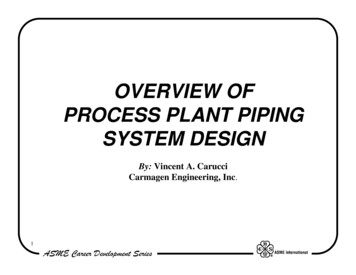
IGVIGV-PP-05B-Rev1-EThe calculation following AD2000 – B1 of the pipe 48,3 mm (annex 1) results in a sufficient wallthickness of 1.0 mm at a working pressure of 40 bar. If the pipe is dimensioned with a wall thicknessof 2.0 mm this results in aa allowed working pressure of more than 80 bar and the least unreinforcedsection is of AD2000 – B9 di 28 mm, if the welding seam is properly compounded.5.3Design MeasuresThe circumferential weld of the pipes shall be designed as testable butt weld seams; socket welds arenot allowed.The wall thickness of min 2mm of DN15 – DN40 pipes effects an ameliorated weldability / control ofweld pool in fixed position than thinner walled pipes and quality requirements can provide5.4Testing and Quality RequirementsSuitable non-destructive test methods are radiographic examination and visual checks of thecircumferential weld of the pipes. If the piping is adequately oversized, i.e. design stress values of 50%, the object-associated radiographic examination is dispensable in the context of a workshopfabrication if the object-associated, as completely as possible performed visual examination confirmsthe fully and properly executed penetration of the weld and formation of the root seam.The visual examination is to be maintained – as far as necessary (accessibility) – by endoscopicprocedures.Randomly non-destructive testing (radiographic examination)The selection of the cryogenic vessel and the number of the seams to be tested is depending on thewelding’s degree of difficulty and the experience of the manufacturer.Minimum extent of radiographic examination:The tests are performed non object-associated (see also AD2000-HP100R [5], section 7.2.6 lastparagraph).In this process, at least 2% of the circumferential welds – with regard to the total amount of fabricatedcryogenic vessels – have to be tested in terms of time and in chronological order.This has to be transposed by object-associated 100% examination of the circumferential welds, atleast to each 50th vessel within the current production, or 100% of the circumferential welds to atleast 1 vessel per quarter.Welding seams which are not accessible on the occasion of the inner visual examination have to beselected particularly on the occasion of the random based radiographic examination.Quality requirements according to quality level C of EN ISO 5817 [9] andNDT – procedure transfer according to EN ISO 17635 [10],Thus, the following criteria shall apply concerning the radiographic examination:EN ISO 17636-1 [11] testing class B (partially A) andEN ISO 10675-1 [12] acceptance level 25.5Suitable piping materialsSuitable piping material is made of austenitic stainless steel, as eg. 1.4301 and 1.4541 acc. to EN10216-5 [13] or EN 10217-7 [14], specified according to AD2000-W2 [15] / AD2000-W10 [16].Butt-welding pipe fittings shall comply with the requirements of EN 10253-4 [22]., type A or type B(or equivalent requirements).Material certification 3.1 according to EN 10204 [17].7
IGV5.6IGV-PP-05B-Rev1-ESuitable welding filler materialsThe relevant third party has to determine the suitability of welding filler materials and weldingconsumables for piping of category II, see AD2000-HP100R [2].For the piping of category I the manufacturer of the piping has to determine its qualification.5.7Requirements in regard to manufacturer, welding personal and welding proceduresThe manufacturer has to be certified according to AD2000-HP0 [18] / EN ISO 3834-3 [19].The manufacturer shall have expert supervisory personnel available.Only qualified welding personal shall be employed.When fabricating welded piping, procedures shall be used, that can be shown to have been masteredby the manufacturer and ensure the uniformity of the welds.5.8Cleanliness RequirementsCleanliness requirements shall comply with EN ISO 23208 [20] and BGRCI-Merkblatt M034 [21].5.9DocumentationThe certification of fabrication is done by the manufacturer (example see annex 2), if appropriate withsupporting documents (e.g. material certifications, welding certifications, reports of non-destructivetesting).6SummaryThis position paper shows the possibilities to perform a substitute test instead of the requiredpneumatic pressure test for piping at cryogenic vessels according EN 13458-2 [1]. The presentedtest concept as a substitute for the strength test includes suitable substitute tests and examinations inorder to meet the requirements of the PED [1] and EN 13458-2.The measures and tests of this test concept are more meaningful than the strength tests and areleading – caused by many years of experience - to properly produced piping at cryogenic vessels,especially to properly established fully penetrated welds and avoidance of root porosities.8
IGV7IGV-PP-05B-Rev1-EReferences[1] Directive 2014/68/EU of the European parliamnent and of the council of 15 May 2014 on theharmonisation of the laws of the Member States relating to the making available on the market ofpressure equipment (PED)[2] EN 13458-2 Cryogenic Vessels – Static vacuum insulated vessels - Part 2: Design, Fabrication,Inspection and Testing[3] PAS 1010 Guideline for the order and manufacture of pressure equipment in accordance with theEC Pressure Equipment Directive 97/23/EC[4] Guidelines of the Pressure Equipment Directive 97/23/EC[5] AD2000 Merkblatt HP100R Construction Regulations Metal Piping[6] EN 13480 Metallic Industrial Piping, especially Part 5 Inspection and Testing[7] AD2000 Merkblatt HP30 Performance of pressure tests[8] Merkblatt T039 Pressure Testing of Pressure vessels and PipingGerman Social Accident Insurance Institution for the raw materials and chemical industryBerufsgenossenschaft Rohstoffe und Chemische Industrie (BGRCI)[9] EN ISO 5817 Welding – Fusion-welded joints in steel, nickel, titanium and their alloys(beam welding excluded) – Quality levels for imperfections[10] EN ISO 17635 Non-destructive testing of welds – General rules for metallic materials[11] EN ISO 17636-1 Non-destructive testing of welds –Radiographic testing – Part 1: X- and gamma-ray techniques with film[12] EN ISO 10675-1 Non-destructive testing of welds – Acceptance levels for radiographic testing –Part 1: Steel, nickel, titanium and their alloys[13] EN 10216-5 Seamless steel tubes for pressure purposes – Technical delivery conditions –Part 5: Stainless steel tubes[14] EN 10217-7 Welded steel tubes for pressure purposes – Technical delivery conditions - Part 7:Stainless steel tubes[15] AD2000 Merkblatt W2 Austenitic and austenitic-ferritic steels[16] AD2000 Merkblatt W10 Materials for low temperatures - Ferrous materials[17] EN 10204 Metallic Products – Types of inspection documents[18] AD2000 Merkblatt HP0 General principles of design, manufacture and associated tests[19] EN ISO 3834-3 Quality requirements for fusion welding of metallic materials - Part 3: Standardquality requirements’[20] Merkblatt M034 OxygenGerman Social Accident Insurance Institution for the raw materials and chemical industryBerufsgenossenschaft Rohstoffe und Chemische Industrie (BGRCI)9
IGVIGV-PP-05B-Rev1-E[21] EN ISO 23208 Cryogenic Vessels – Cleanliness for cryogenic service[22] EN 10253-4 Butt-welding pipe fittings - Part 4: Wrought austenitic and austenitic-ferritic (duplex)stainless steels with specific inspection requirements10
IGVIGV-PP-05B-Rev1-EAnnex 1: Exemplary calculation of pipe 1.4541 / DN40 / PN40 2,0mmm/40bar Prg-Version: ADH07- 2011 / CS und Betriebsz. K min{Rp0.2, 1.5*Rm/2.4} , S 1.5Symbols and units according AD2000-Merkblatt B0Da outer diameter of the cylindrical shell in mmp design pressure bars required wall thickness mmse nominal wall thickness mmc1 absolute value of negative tolerance mmc2 corrosion allowance mmK design strength at design temperature N/mm²S safety factorv welding coefficientCylindrical spheres subjected to inner pressure according AD2000-Merkbl. B1Da 48.30 mmse 2.00 mmc1 0.40 mmmaterial: 1.4541 DIN 17457c2 0.00 mmOperating situationpressure 40.00barstatic height 0.00 mfluid density 1.00p (AD-B0 section 4.1) 40.00 bartemperature 50 CK 235 N/mm²S 1.50v 1.00Testing situation44.00 bar0.00 m1.00 kg/dm344.00 bar20 C235 N/mm²1.051.00Calculation of the required wall thickness subjected to inner pressureAccording to AD2000-Merkblatt B1, formula 2:s Da*p/[20*K*v/S p] c1 c2 1.01 mm0.87 mmMinimum wall thickness according to AD2000-B1 2.00 mmRequired pipe wall thickness s erf. 1.01 mmNominal pipe wall thickness se 2.00 mmThe calculation of openings according AD2000-B9 is required for openingswith diameters di 28 mm .11
IGVIGV-PP-05B-Rev1-EAnnex 2: Example: Manufacturer declaration of complianceDeclaration of CompliancePiping of the Cryogenic Vessel according PED 2014/68/EU /EN 13458 / EN 13480 / AD2000Manufacturer:Approval according AD2000-HP0, datedor according EN ISO 3834-3, datedType of Vessel:Serial-Number:Year Built:1.Technical Data of the PN40- Piping1.1 Used MaterialsAll used material are fullfilling the requirements according AD2000-HP100R section 5or EN 13480-2 Table B.2-111.2 Dimensions of the used oversized pipes (min. PN80)Pipe 48,3 mm wall thickn. s:(min. 2,0 mm); Material:ENKat.II / Module A1Pipe 42,4 mm wall thickn. s:(min. 2,0 mm); Material:ENKat.II / Module A1Pipe 33,7 mm wall thickn. s:(min. 2,0 mm); Material:ENArt.4,para.3Pipe 26,9 mm wall thickn. s:(min. 2,0 mm); Material:ENArt.4,para.3Pipe 21,3 mm wall thickn. s:(min. 2,0 mm); Material:ENArt.4,para.3Pipe 17,2 mm wall thickn. s:(min. 1,6 mm); Material:ENArt.4,para.3Pipe 12,0 mm wall thickn. s:(min. 1,0 mm); Material:ENArt.4,para.3Pipe 10,0 mm wall thickn. s:(min. 1,0 mm); Material:ENArt.4,para.3Pipe 8,0 mm wall thickn. s:(min. 1,0 mm); Material:ENArt.4,para.3Pipe 6,0 mm wall thickn. s:(min. 1,0 mm); Material:ENArt.4,para.31.3 Declaration of the used welding procedures (TIG), the deployed welders and the used welding fillermaterialsAll weldings were performed within the scope of valid welding procedure qualifications according EN ISO15614-1 and with qualified welders according EN ISO 9606-1, and by using of approved welding fillermaterial.The execution of the welding works (TIG) was surveyed in the context of a special monitored workshopprefabrication .12
IGVIGV-PP-05B-Rev1-E13
The AD2000-Merkblatt, especially AD2000-HP100R as well as EN 13480, contain comprehensive regulations for design, fabrication, inspection and testing - corresponding to the state of art - for the piping of a cryogenic vessel. EN 13458-2 does not contain adequately formulated requirements for piping. You can only find: