Transcription
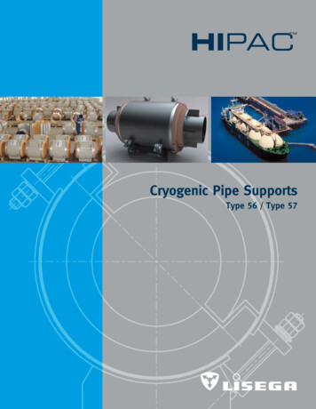
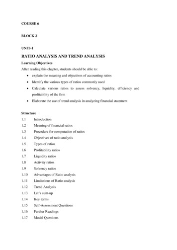
65International Journal of Scientific & Engineering Research, Volume 7, Issue 7, July-2016ISSN 2229-5518Designing and Analysis of Cryogenic StorageVesselsHepsiba Seeli, Sri Harsha Dorapudi, Pasala Venkata Satish, Samanthula Naveen KumarAbstract—Cryogenics is a study of science which deals with the behavior of extreme low temperatures. Cold converts is a kind of apressure vessel which is meant for storage of liquid oxygen and nitrogen or argon under required pressure conditions. The materials usedfor this equipment are discussed and analysed in this paper. The designing procedure follows according to the industry norms.The procedure conforms to ASME SECTION 8, DIVISION-1 and DIVISION-2. The procedure for designing nitrogen cold convertor to therequired specifications has been studied and modified to create a perfect storage cryogenic vessel. The design calculations and resultshave been shown.Index Terms— Diameter, Liquid nitrogen, Maximumm shear stress, Storage capacity, Outer-shell, Inner-shell, Principal stresses,Thickness, Von misses Stress.Volumetric Strain.—————————— ——————————1 INTRODUCTIONTHIS research paper gives the over view of designing andanalysis of the cold converter storage vessel, in wich liquid oxygen and liquiud nitrogen or liquid argon arestored safely. The tank must sustain the working pressure otherwise the tank explodes and causes damage to itself and to itssurrounding equipments.Cryogenics refers to the entire phenomenon occurring below -150 or 123K. Cryogenics enginnering involves the designand development of systems and components which produce,maintain, or utilize low temperatures.Cryogenics vessels are designed for storage and transportof liquid gases at sub-zero temperatures. Manufacturing ofcryogenic tanks requires special technical and sophisticatedfabrication techniques. Universal has developed thenecessarytechnology and has been manufacturing these crypgenicequipment like cryogenics vessels sice last 9 years.IJSER1.2 STORAGE VESSEL COMPONENTSDifferent gauges and valves are required to monitor and stabilize the cryogenic vessel and these guages have a precise measauring capability, otherwise smallest change in the presurevariations can leads to trouble. Hence different parameters ofthe vessel are contiounsly monitored.The different gauages and valves which are used in the cryogenic vessel are vaporator, liquid container gauge, vaccumbursting disk, vent valve, pressure building valve,pressurebuilding coil, pressure relief valve, Presure gauge, inner container bursting disk, liquid fill and withdrawl valve, economierregulator, vent valve.e.t.cAll thses gauges and valves have the capability to work even atthe higher pressure environments without any malfunction.Fig 1.1 components of Storage vesselAll these components are carefully monitored and regulatedby computers. These computer are pre-programmed to takenecessary counter measures to avoid any accidents.The components and computers are powered by a local battery unit.The important components in the cryogenic storage vessel arethe pressure gauge and the pressure relief valve, because thepressure in storage vessel should always have to be maintained at a required presuure level and if it is not maintainedthen the storage vessel may leads to malfumction.The various components of cold convertor are as follows:IJSER 2016http://www.ijser.org
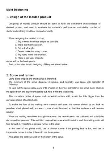
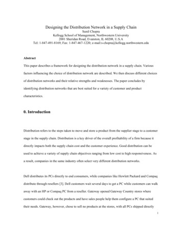
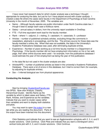
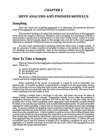
66International Journal of Scientific & Engineering Research Volume 7, Issue 7, July -2016ISSN 2229-5518ShellsThe shells of cold converter are of cylindricalsections. These are mainly two shells named as inner shells andouter shells. The inner shell is made up of stainless steel whereas the outer shell is made up of carbon steel. The annular spacebetween the shells is evacuated and is perlite insulation.Dished endsThese form the end closer to cold converters. Inthe dished ends a sudden change in direction is avoided at thejunction of cylindrical shell and formed end with a gradualchange n shape reduces the local discontinuity stresses at thejunction. The dished end may be hemi-spherical, tori-sphericalor ellipsoidal.Fig 1.2 Structure of Storage vesselSkirtIt provides support to the entire vessel. The skirt is usuallywelded directly to the vessel either to the bottom dished end oroutside of the cylindrical shell. The bottom of the skirt of thecold converter must be securely anchored to the concretefoundation by means of anchor bolts embedded in the concreteto prevent overhauling from the bending moments induced bywind and seismic loads.NozzlesIJSERNozzles are connections through which the vessel isconnected to the piping instrumentation and other controlequipment. These are welded to the shell. Nozzles can be fromseamless pipes, forged hallow bars. These are connected bymeans of flanges, screw type connections or directly welded.Pressurization coilMultilayer insulation, powder insulators and fabric materials are used as insulators in larage capacity crypgenic containers.An insulation materials used to insulate the cryogenic fluidsfrom the vapour or air and the other gases which are present inthe atmosphere. The effectiveness of the storage vessel dependon the insulation hence it is very important parameter thatshould be considered in the design of the cryogenic storagevessels.And these two shells (tanks) are connected by a supportblocks, these support blocks will acts as a stiffners and it helpsin maintaining structural stability of the vessel it absorbs thestresses and it keep the product shell securely.To minimize heat transfer and sustain very low temperatures, the storage vessel must be specially designed. Storagevessels for liquid oxygen, liquid nitrogen and liquid argon arecommercially available in various capacities. The storage vessels may be vertical, spherical, or horizontal depending on thesite and consumption requirementsThe unit consists of aluminum star fins by the side oftank and is gravity fed by valve and the desired pressure canbe obtained. Its output is controlled by the regulator (pressurecontrol valve).Control cabinetThe valves gauges and fittings required for the operating the convertor are located in light alloy shelter mounted onthe outer shell. For example: vacuum gauge, rupture disc, inletand outlet valves etc.1.3 Structure of Cryogenic Storage vesselThe cryogenic storage vessel is designed in such a way that ithas two different shells, first one is called the innershell orproduct container and the other is called as outershell and it isalso know as vaccum jacket. The air between the gaps aresucked out with the help of air separation unit and it is madevaccumed for better insulation. In some cases different types ofpowders and gasses are used for insulation and the type ofinsulation is always independent on the type of storage andenvironmental conditions.1.3.2 Air separation unit.The air is sucked from atmosphere. The sucked air is compressed in a five stage compressor with an inter cooler. Thecompressed air consists of oil, moisture and carbon dioxide.These impurities are obstructions for the liqueficaction becausecarbon dioxide and moisture forms ice at lower temperatures,which is obstruction for the flowing fluids. So these impuritiesare to be removed.The compressed air is passed through a filter, which separateoil from the compressed air. The oil free compressed air is nowpassed through a refrigerating unit, which cools the compressed air. These droplets are collecting in a separate vessel.Now the air is passed through a vessel consisting of molecularsieves, which absorbs carbon dioxide present in the compressed air.IJSER 2016http://www.ijser.org
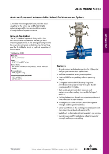
67International Journal of Scientific & Engineering Research Volume 7, Issue 7, July -2016ISSN 2229-5518Fig 1.3 Air separation unitNow this air is passed through post filter, which removes further impurities. The filtered air is passed through post filter,which removes any further impurities. The filtered air is sentthrough the cold box. This cold box is mainly consists of thefollowing1) Heat exchangers2) Exchange turbines3) Inlet and outlet manifolds4) A column consisting of aluminium trays.IJSERAir separation process cycleCompressionFiltrationthis low temperature the air is liquefied. The liquid air is thenpassed through a column consisting of aluminium trays fromtop to bottom. During this flow the evaporation of nitrogenand other gases takes place and only oxygen is collected inbottom reservoirs. The liquid nitrogen is produced at the top ofthe column. Due to this gaseous nitrogen can be liquefied bygiving the heat energy to the liquid oxygen. Here the liquidoxygen is evaporated. This liquid nitrogen is formed at thecolumn and Pumped to the cold convertor.The condensable gaseous nitrogen is passed through the heatexchanger, which cools the incoming compressed air, thus liquid nitrogen and oxygen produced and collected in cold convertor.Argon which has 0.93% content of air which has a boiling pointin between oxygen and nitrogen presented as impurity in theboth liquid nitrogen and liquid oxygen. In order to get pureliquid nitrogen n argon percentage should be reduced. Thiscan be down by using the other column, which separates argon.RefrigeratingunitVesselPost filterCold boxCold box2. Designing of Cryogenic VesselDifferent variables like the thickness of the product vessel, diameter of product vessel, thickness of the outershell, diameterof the outershell and the thickness of the stiffners are calculated. Those calculations are depended on the type of designcodes.2.2 Design codesA design code is a document that sets rules for the design of anew development. It is a tool that can be used in the designand planning process. The design and manufacture of pressurevessels are done according to some regulations and codes.They assure safety in operations, quality control and assurance. The codes that are adopted by pressure vessels manufactures are1) ASME selection VIII division- I & II (American codes)HeatexchangersExpansionturbinesInlet and out letmanifoldsA columnconsisting ofaluminium rays2) PD 5500 (British code)3) AD Merkblatter (German code) and4) IS 2825 (Indian code)Fig 1.4 Flow chart of Air separation unitThe compressed air is passed through heat exchanger, whichreduces the temperatures of the air around -140 C. The coolingof air is allowed by passing the cold non condensable gasesand gaseous nitrogen. The cold air is passed through the expansion turbine in which the compressed air is expanded. Duethis expansion the temperature is reduced to around -180 C. AtThe basic aims of the codes are same,but their approach is different. Their use of raw materials, historical back ground, design and manufacture are different fordifferent codes in different countries.The features and limitations of codes are given belowIJSER 2016http://www.ijser.org
68International Journal of Scientific & Engineering Research Volume 7, Issue 7, July -2016ISSN 2229-55181) ASME selection VIII division- 1This code provides the formulas to compute thickness and stresses of the vessel. They provide procedures todesign the vessel. According to this code the wall thickness iscomputed by some assumptions. They should not exceed maximum allowable stresses, stresses should be uniformly distributed and there should be higher factor of safety. The limitations are1) Pressure should not exceed 3000 Psi.2) Vessels having internal or external operation pressure notexceeding 15Psi with no limit on size.Series HSeries HPSeries NSeries SSeries WManufactureManufacturing and testingNon metallic materialsSpecial casesmetallic materials5) IS 2825This code covers minimum construction requirements for the design, fabrication, inspection, testing and certification of welded unfired pressure vessels in ferrous as well asin non-ferrous materials. This code does not include1) Vessel designed for pressure exceeding 200kgf/cm23) Nominal water containing capacity of 120 gallons or less.2) When the ratio of outside to inside diameter of the shell exceeds 1.54) Vessels having an inside diameter not exceeding 6” with nolimitation on pressure.3) Hot water supply storage tanks heated by steam or any other indirect means.2) ASME selection VIII division-24) Vessels having an internal operating pressure not exceeding1 kgf/cm2 with nomination size.IJSERIn this code lower safety is considered as a result higher allowable stresses are permitted in designing the vessel. Italso ensures safety, design, fabrication and quality control. Thiscode is applicable only when the vessel is fixed and it has nopressure limits.3) PD 55002.3 Design calculations.Different calculations of several variabels are shown belowThis code specifies requirements for design, construction, inspection and testing of welded pressure vessels. Thiscode does not include vessels that are subjected to directlygenerated heat of flame impingement from a firing process.The limitations are pressure inside the vessel should not exceed 140m bar above atmospheric pressure and 6m bar belowatmospheric pressure. It is not applicable for low pressure andsingle vertical axis of revolution, multi layer vessels, andtransport pressure vessel.4) AD MerkblatterSeven-trade association of Germany, which togetherforms the AD codes, compiles the AD Merkblatter. This codecovers safety requirements, which must be adopted for normalcondition of operation. The necessary requirements are satisfactory design, manufacture and operation of the pressure vessel. To a large extent AD Merkblatter code is based on DINstandards (German standards). AD Merkblatter consists of thefollowing series.Series ASeries BSeries C5) Vessel having an internal diameter not exceeding 150 mmwith no limitation on sizeEquipmentDesignFundamentals2.3.2 Capacity calculations 65 m3Net capacityQ1Vapour space provided in tank 5% of capacityGross capacity of cold converter Q net capacity vapourspace 68.25 m3Inner diameter of inner cylinder Di 2698 mmRadius of inner dished end ri 1350 mmVolume of two dished ends Vd 4/3 πri3 10.277 m3 – both 5.138 m3 – each dishedends Volume of cylindricalshell LD2π/4Volume of cylindrical shell gross capacity – volume ofdished ends 57.98 m3From the above two equationsLD2π/4Length of cylindrical shell L (TL to TL)Height of the shell (HD2π/4)HIJSER 2016http://www.ijser.org 57.98 m3 10.14 m 59.85 m3 10.473 m
69International Journal of Scientific & Engineering Research Volume 7, Issue 7, July -2016ISSN 2229-5518Height of the liquid shell height of shell – one dished end 10.473 1.350 11.823 m3Pressure due to static head height of liquid density of fluid/10 0.957 kg/cm2Hence design pressure working pressure 1.1 atmosphericpressure pressure due to static head 18.5 1.1 1.0332 0.957 22.3402 kg/cm22.3.3 Design of inner shellDo/t 135.564From ASME SEC VIII DIV 1From graph factor A 0.00008Since the graph (HA- 1) is falls on left sidePressure Pa 2AE / 3(Do/t)Pa 5.34 psiExternal pressure P atmospheric pressure 15 psiSince Pa P the design is not safe, so we use stiffener rings2.3.6 Design of outer cylindrical shell design (under external pressure)We are using carbon steel SA 516 TP 70.Inner diameter of outer cylindrical shell 3050 mmThickness of outer cylindrical shell 20.2 mmOuter diameter of outer cylindrical shell Do 3074 mmCorrosion allowance C.A 3.0Effective length L 1240.23 mmL/DO 3.65DO/t 152.1782From ASME SEC VIII DIV 1From graph factor A 0.00009As the graph is falls down on left side we cannot obtain factor‘B’ valuePressure Pa 2AE / 3(Do/t)Pa 9.448 psiExternal pressure P 15 psiSince Pa P the adopter dimensions are not adequate to withstand the external pressure. For that purpose we have to provide stiffener rings on external cylindrical shell.2.3.7 Stiffener ring calculations under external pressureInner shellDesign of inner cylindrical shell (under internal pressure)Thickness of shell (as per ASME SEC VIII DIV 1)T PRi / (SE- 0.6P) C.A T.AWhereP design pressure 22.3402 kg/cm2S allowable stress 1406.14 kg/cm2Ri radius of inner shell 1350 mmE joint efficiency 1C.A corrosion allowance 0T.A thinning allowance 0Hence thickness T 20.13 mm 20.2 mmAdopted thickness 20.2 mmIJSER2.3.4 Design of inner dished endsDished ends are of spherical typeThickness of dished end isT PRi / (2SE- 0.2P) C.A T.AWhereP design pressure 22.3402 kg/cm2Ri 1350.33 mmS 1406.14 kg/cm2C.A 0T.A 1We provide 2 stiffener rings, so there are 3 equal spaces.Outside diameter of cylindrical shell Do 2722 mmProvided thickness t 20.2 mmCorrosion allowance C.A 0 3680.076mmLength between stiffener rings Ls(Assuming 2 stiffener rings)L/Do 1.35Do/t 137Hence thickness of inner dished end Td 11.74 mm 12 mmAdopted thickness Td 12 mmFrom ASME SEC VIII DIV 12.3.5 Inner cylindrical shell design (under externalpressure)External diameter Do 2698 (2 20.2) 2738.4 mmThickness of inner shell t 20 .2mmLength of inner cylindrical shell 10140.23 mmEffective length L 10140.23 2(rd/3)Whererd radius 1350 mmL 11040.23 mmFrom graph factor A 0.00023From graph factor B 3000Pressure Pa 4B / 3(Do/t)Pa 29.684 psiExternal pressure P 15 psiSince Pa P the adopted dimensions are not adequate to withstand the external pressure. So, our design is safe.IJSER 2016http://www.ijser.org
70International Journal of Scientific & Engineering Research Volume 7, Issue 7, July -2016ISSN 2229-5518Outer shellOutside diameter of cylindrical shell DoProvided thickness t 3074 mm 20.2mmCorrosion allowance C.A 3 mmLength between stiffener rings Ls 3740 mmL/Do 1.218Do/t 152.17From ASME SEC VIII DIV 1From graph factor A 0.00025From graph factor B 3400Pressure PaASME code specified that it is not necessary to post weld, heattreatment up to and including 2 inches thickness (up to about50mm).Aluminium alloysAluminium alloys like 5083 (Mg0.445%, Mn 0.6% and cr 0.15%), 6003 (Mn 1.26% and Cu 0.12%)are used in manufacture of cryogenic storage vessel, columnsin air separation plant and brazed aluminium of heat exchangers. These show no ductile to brittle transformation even downto the temperature of liquid helium i.e., -269 C.The toughness properties of aluminiumare so well known that it was not considered necessary to specify the minimum value in ASME or ASTM codes. Notchedyield ratio, tear resistance, critical stress intensity is high. Fatigue strength also increases with decrease in temperature. 4B / 3(Do/t)Copper alloysPa 29.79 psiExternal pressure P 15 psiSince Pa P the adopted dimensions are not adequateto with stand the external pressure. So, our design issafe.Under this geometry conditions the vessel is designed.Some dimensions are calculated while some others are assumed and some others are taken from design standard codesand graphsCopper alloys like alpha brass andphosphorous-di-oxide, copper were easy material of construction for cryogenic equipments. Even today copper tubes areused for trays in small air separation plants. Copper has lowyield strength in annealed condition. Copper alloys have lesseryield strength when compared to steel and are unaffected bytemperature changes.IJSER3 CRYOGENIC MATERIALSAustenitic steels, stainless steels, fine graindouble normalized and tempered nickel steels, copper andaluminum are excellent materials, which can be withstand cryogenic temperature.Alluminum and Nickel steels are better suitable for production of the cryogenic storage vessel hence in order to select onestress analysis should be done on both materials and the basedon the stress analysis results we can select a material which isbest suited for the cryogenic tank production. And that material is later discussed in conclusion4 DESIGN ANALYSIS OF CRYOGENIC VESSEL.Stainless steelsAustenitic stainless steels are suitedfor cryogenic applications as they remain tough and ductileeven at -269 C.The first simualation is done on the cryogenic vessel which ismade up of with the aluminium 5083. And its simulation results are shown below4.2 Simulation: 19% Nickel steels9% nickel steels are usually classified asferrite steel however this constitutes austenitic ferrite andmagnetite. The presence of austenitic has given excellentstrength and resistance to brittle fracture.The decrease in ductility with decreasein temperature below zero is very gradual and as chirpy vnotch values are above 25 Ft lbs (346 or 4.4 kg/cm2) at -200 C.In case of fabrication proven safety and favorable cost hasmade it widely used material ins cryogenic equipment for storing and transporting liquefied gases such as Nitrogen, Methane and Ethylene.Extensive tests to destructions are carried out on tanks filledwith liquid nitrogen have demonstrated that quenching andtempering and that post weld treatment was not beneficial.Analyzed File:Cryogenic vesselAutodesk Inventor Version: 2015 (Build 190159000, 159)Creation Date:15-May-16, 10:50 PMSimulation Author:Pasala Venkata SatishProject Info (iProperties)AuthorPasala Venkata SatishPart Number 2ndccDesignerPasala Venkata SatishDate Created 07-May-16IJSER 2016http://www.ijser.org
71International Journal of Scientific & Engineering Research Volume 7, Issue 7, July -2016ISSN 2229-5518PhysicalMaterialAluminum 5083 87 Cold FormedDensity0.0960986 lbmass/in 3Mass31879.8 lbmassArea4762870 cm 2Volume5436260 cm 3x -0.0000000000029165Center of Gravity y -525.627z -154.6 cmMagnitude 250.000 psiSelected FacescmcmNote: Physical values could be different from Physical valuesused by FEA reported below.General objective and settings:Design ObjectiveSingle PointSimulation TypeStatic AnalysisLast Modification Date15-May-16,PMDetectModesandEliminateMesh settings:10:45IJSERRigidBodyNoFig 4.2.1 Selecting face for pressureAvg. Element Size (fraction of model diameter) 0.1Min. Element Size (fraction of avg. size)0.2Grading Factor1.5Max. Turn Angle60 degCreate Curved Mesh ElementsYesThe applied pressure in the vessel is 250 psi according to theASME standards and the external pressure is taken as 150 psi.The Figure 4.2.2 indiactes the diferent constrains that are located at the different location of the Storage vessel. The constrains are displayed in blue in color.Material(s)NameGeneralMass Density0.0960986lbmass/in 3Yield Strength41335.8 psiUltimateStrengthStressPartName(s)Constraint Type Fixed ConstraintAluminum 5083 87 Cold FormedTensile55839.5 psiYoung's Modulus10007.6 ksiPoisson's Ratio0.33 ulShear Modulus3762.26 ksiCryogenic VesselOperating conditionsLoad Type PressureIJSER 2016http://www.ijser.org
72International Journal of Scientific & Engineering Research Volume 7, Issue 7, July -2016ISSN 2229-5518Fig 4.2.2 constrained position in vessel for analysisResult SummaryNameMinimumVolume5.43626E 009 mm 3Mass31879.8 lbmassVonStressMisesStrain XX-0.00164065 ul0.000974262ulStrain XY-0.000764729 ul0.000711764ulStrain XZ-0.00124247 ul0.00118883 ulStrain YY-0.00124163 ul0.000576865ulStrain YZ-0.000711151 ul0.00059584 ulStrain ZZ-0.0016662 ul0.000855221ulContactPressure 0 MPa8.51499 MPaContactPressure-1.67133 MPaX1.55096 MPaContactPressure-0.00151738 MPaY8.16541 MPaContactPressure-2.41261 MPaZ1.7797 MPaMaximumIJSERVon Mises Stress0.000866688 MPa 117.146 MPa1stPrincipal-23.4491 MPaStress89.0687 MPa3rdPrincipal-125.807 MPaStress53.9125 MPaDisplacement0 mm2.4775 mmSafety Factor2.43287 ul15 ulStress XX-125.806 MPa77.8312 MPaStress XY-39.6739 MPa36.9261 MPaStress XZ-64.459 MPa61.6759 MPaStress YY-79.1859 MPa58.5517 MPaStress YZ-36.8943 MPa30.912 MPaStress ZZ-124.757 MPa78.149 MPaX Displacement -2.2528 mm2.20901 mmY Displacement -1.06415 mm1.02019 mmFig 4.2.3 application of von mises stressZ Displacement -2.26653 mm2.32907 mmThe maximum stress produced in the vessel is 117.1 mpaand its location is near to the welded region of the vessel.EquivalentStrain0.00000001415680.00152525 ulul1stPrincipal-0.000021337 ulStrain0.000974366ul3rdPrincipal-0.00168837 ulStrain0.0000616597ulIn analysis 1st principal stresses and 3rd principal stressesare important hence those two analysis reports are also shownbelow. The different colors indicates the different stresses acting at the different locations of the vesselIJSER 2016http://www.ijser.org
73International Journal of Scientific & Engineering Research Volume 7, Issue 7, July -2016ISSN 2229-5518IJSERFig 4.2.6 Safety FactorFig 4.2.4 principal stress acting on vessel4.3 Simulation: 2The second simualation is done on the cryogenic vessel whichis made up of with the Nickel-Copper Alloy 400. And its simulation results are shown belowAnalyzed File:Cryogenic VesselAutodesk Inventor Version: 2015 (Build 190159000, 159)Creation Date:15-May-16, 10:54 PMSimulation Author:Pasala Venkata SatishProject Info (iProperties)Author Pasala Venkata SatishPart Number 2ndccFig 4.2.5 3rd principal stress acting on vesselDesignerPasala Venkata SatishDate Created 07-May-16PhysicalMaterialNickel-Copper Alloy 400Density0.319004 lbmass/in 3Mass105827 lbmassArea4762870 cm 2IJSER 2016http://www.ijser.org
74International Journal of Scientific & Engineering Research Volume 7, Issue 7, July -2016ISSN 2229-5518Volumeboth simulations hence pictures of selected phases are skipped.The applied pressure in the vessel is 250 psi according to theASME standards and the external pressure is taken as 150 psi.5436260 cm 3x -0.0000000000029165 cmCenter of Gravity y -525.627cmz -154.6 cmNote: Physical values could be different from Physical valuesused by FEA reported below.General objective and settings:Design ObjectiveSingle PointSimulation TypeStatic AnalysisLast Modification Date15-May-16,10:53 PMResult SummaryNameMinimumVolume5.43626E 009 mm 3Mass105827 lbmassVon Mises Stress0.00162306 MPaMaximum117.319 MPa1st Principal Stress -21.2942 MPa84.0095 MPa3rd Principal Stress -125.093 MPa50.3036 MPaDisplacement0 mm0.953784 mmSafety Factor1.87523 ul15 ulMesh settings:Stress XX-125.092 MPa73.8974 MPaAvg. Element Size (fraction of0.1model diameter)Stress XY-38.9344 MPa36.2063 MPaStress XZ-64.2913 MPa61.4116 MPaMin. Element Size (fraction of0.2avg. size)Stress YY-76.3419 MPa54.3181 MPaStress YZ-36.5436 MPa30.2902 MPaGrading FactorStress ZZ-123.735 MPa74.8874 MPaX Displacement-0.868379 mm0.853062 mmY Displacement-0.40084 mm0.384769 mmZ Displacement-0.875101 mm0.898574 mmEquivalent Strain0.00000000941988 ul 0.000583016 ulDetect andBody ModesEliminateRigidIJSER1.5Max. Turn Angle60 degCreate Curved Mesh YesNickel-Copper Alloy 4001st Principal Strain -0.00001081 ul0.000365483 ulMass Density0.319004lbmass/in 33rd Principal Strain -0.000651899 ul0.0000239238 ulStrain XX-0.000634373 ul0.000365446 ulYield Strength31908.3 psiStrain XY-0.000285548 ul0.00026554 ulUltimateStrengthStrain XZ-0.000471517 ul0.000450397 ul80931.1 psiStrain YY-0.00046364 ul0.000221503 ulStrain YZ-0.000268013 ul0.00022215 ulStrain ZZ-0.000643419 ul0.000322807 ulContact Pressure0 MPa7.99854 MPaTensileYoung’s Modulus26005.3 ksiPoisson’s Ratio0.315 ulShear Modulus9887.93 ksiCryogenic vesselContact Pressure X -1.61752 MPa1.50136 MPaContact Pressure Y -0.00151559 MPa7.64802 MPaContact Pressure Z -2.33956 MPa1.72514 MPaOperating conditions:Load Type PressureMagnitude 250.000 psiThe body contacts along with selected faces are same for theIJSER 2016http://www.ijser.org
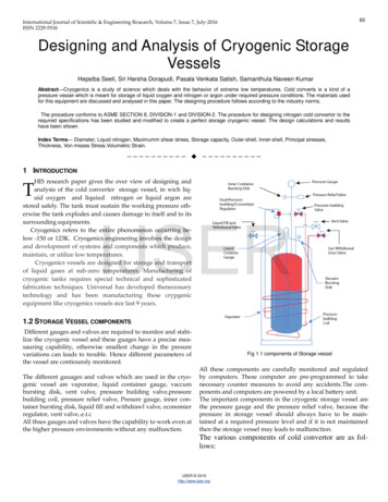
75International Journal of Scientific & Engineering Research Volume 7, Issue 7, July -2016ISSN 2229-5518Fig 4.3.1 constrained position in vessel for analysisFig 4.3.3 1 st principal stress acting on vesselIJSERFig 4.3.4 3rd principal stress acting on vesselFig 4.3.2 application of von mises stressIn Fig 4.3.1 and 4.3.2 shows the coffnstraints locations and thevon mises stress are showed at the differentlocation of the cryogenic storage vessel. The maximum stress applied on the vessel is shown in the simulation and it is 117.3 Mpa.The fig 4.3.3 and 4.3.4 shows the 1 st principal stress and the 3rd principal stresses which are produced in the vessel with theapplication of pressure. The maximum stress values producedin 1 st principal stress is 84.01Mpa and the maximum stressproduced in the 3 rd principal stress is 50.3 MpaIJSER 2016http://www.ijser.org
76International Journal of Scientific & Engineering Research Volume 7, Issue 7, July -2016ISSN 2229-5518[6] S. Kamiya, K. Onishi, E. Kawagoe, and K. Nishigaki, A large experimental apparatus for measuring thermal conductance of LH2 storage tankinsulations, Cryogenics, vol. 40, pp. 35-44, 2000.[7] B.D. Manshadi, H. Mahmudi, A. Abedian, R. Mahmudi, A novel method for materials selection in mechanical design: Combination of non-linearlinearization and a modified digital logic method, Materials and Design,28, 2007, 8–15.[8] O.Khemis. M.Boumaza, M.Ait Ali,M.X.Francois (2004) “Measurementof heat transfers in cryogenic tank with several configurations”.[9] TM Flynn, “Cryogenic Engineering”, third edition.[10] R.V. Rao, A material selection model using graph theory and matrixapproach, Material Science and Engineering A, 431, 2006, 248–255.[11] D.S.Kumar, Heat and mass transfer, 7th edition, S.K.Kataria & sons,2010, pp 436-439. Hepsiba Seeli, Post graduate of Andhra University (AU) 2011, MechanicalEngineering with specialization in (CAD/CAM). Currentl working as Assistant Professor at Pydah College of Engineering teaching Mechanical Engineering courses and facilitating laboratory. In the past, I worked as a Research Assistant in the E-Foundry Lab at IIT Bombay., E-mail:seelihepsi@gmail.com Co-Author Sri Harsha Dorapudi, post graduae of NIT Tiruch, currently working as Assistant Professor at MVGR College Of Engineering., INDIA. Co-Authors Pasala venkata satish and samanthula Naveen Kumar, both areGraduates from B. tech 2016, Mechanical Engineering at Pydah College of Engineering, Jawaharlal Nehru technological University Kakinada(jntuk).(This information is optional; change it according to your need.).IJSERFig 4.3.5 Safety FactorThe figure 4.3.5 shows the information regarding
The design calculations and results have been shown. . should be considered in the design of the cryogenic storage vessels. And these two shells (tanks) are connected by a suppor. t . blocks, these support blocks will acts as a stiffners and it helps in maintain