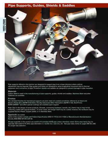
Transcription
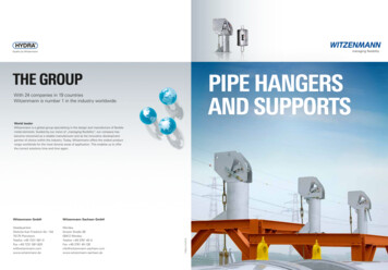
Cryogenic Pipe SupportsType 56 / Type 57
Edition August 2018LISEGA reserves the right to introduce revisions inthe interest of further technical developments.
Cryogenic Pipe SupportsType 56 Rest- and Guide Supports /Type 57 Line Stop and Fixed SupportsTable of ContentsSupports for Cold and Cryogenic Applications4Cryogenic Pipe Support Base / Design5Type Designation System6Double and Multiple Clamp Base Pipe Supports7Special Design7Type 56 01 .0 to 56 97 .98Type 57 01 .0 to 57 97 .919
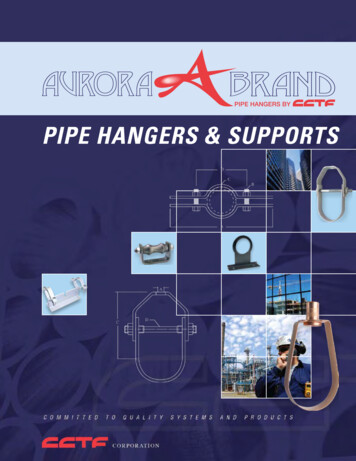
CRYOGENIC PIPE SUPPORTS TYPE 56 / TYPE 57Supports for Cold and CryogenicApplicationsLISEGA offers a complete range of insulated cryogenic pipe supports for all kindsof low temperature pipe systems. Theseproducts are normally used in industrialprocesses for the production, transportand distribution of liquefied gases. Thesecan be propane and butane (LPG), methane(LNG), ethylene, nitrogen or ammonia.Warehouse for curing the foamPreassembled cryogenic pipesupportsThe LISEGA cryogenic pipe supports arestandardized and designed according torecognized international technical codesand standards. They cover pipe sizesranging from OD 21.3mm to OD 965.2mm,with insulation thicknesses from 25mmto 250mm. The supports are made frommaterials suitable for the specified loadsand temperature range (operating temperature down to -196 C).Insulation MaterialThe insulation material of the cryogenicpipe supports is made from fire-retardingpolyurethane foam of high density (HDPUF) and forms an integral part of thepiping insulation.Production of HD-PUF ShellsSpecial design for pipe diameter1625,6mm4Nominalthickness ofinsulation(mm)Thicknessof individualsteps(mm)8040 / 4010050 / 5013050 / 40 / 4015050 / 50 / 5018050 / 80 / 5020050 / 100 / 5025075 / 100 / 75The HD-PUF is monolithically molded inheavy duty molds under carefully controlledconditions in respect of temperature andhumidity. This process provides uniformproperties and ensures dimensionalstability with no warping. It also producesclean sharp edges that fit neatly with theadjacent line insulation material on site.To guarantee form stability, the insulationcradles are carefully stored for a fixedperiod of time in order to harden. Themoldings incorporate carefully sized stepjoints (radial and longitudinal) to matchthe layering of the adjoining line insulation.This method, also known as „shiplapping“,provides a reliable interlocking interfacewith each layer and prevents a direct heatpath from the surface of the insulationthroughto thesurfaceof the pipe.Insulationfoam cradleswith thicknessesup to 50mm are supplied as single layerwithout a step. Foam cradles with a thickness of 80mm and 100mm are supplied assingle layer with an extended step at eitherend. The foam cradles for type 56 with athickness of 130mm and above are suppliedin two layers with two steps. The insulationfoam cradles for type 57 line stop & fixedsupports will be supplied as monolithicallymolded segments to achieve axial load transmission. The single-layer as well as thedouble-layer HD-PUF insulation cradleshave stepped, longitudinal gaps. The sizeof these joints must be adjusted duringinstallation to a specified gap dimension,so that the clam ping force applied by thedisc spring bolting prevents a relativedisplacement between clamp base andpiping. Once installed the longitudinalgaps shall be filled with a resilient foaminsulation material.A laminated aluminum/polyester foil isfactory-bonded to the outermost surfaceof the outer layer of the HD-PUF assembly.This vapour barrier is supplied oversizedto overlap the longitudinal joints and issealed at site with adhesive tape of thesame material. Directly after installationof the cryogenic pipe support, all exposedHD-PUF foam surfaces must be protectedto prevent moisture ingress. As a rule, acryogenic, fire-retarding vapor barrier ofelastomer mastic is applied for this purpose.The HD-PUF is available in three standarddensities. They are supplied in differentcolors for ease of identification.160 kg/m3 - yellow224 kg/m3 - red320 kg/m3 - green
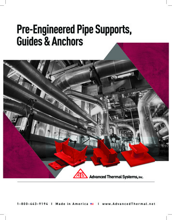
Cryogenic Pipe Support BaseLISEGA’s standardized cryogenic pipesupports are designed in such a way thatthey clamp the pipe mechanically viadisc spring bolting. The clamp basesubstructure that supports the HD-PUFfoam is made of carbon steel and ishot-dip galvanized as a standard.Material qualities, welding and surfacetreatment correspond to the LISEGAstandard specification (see pages 0.9and 0.10 in the main catalog “StandardSupports 2010”).In the production and preassembly ofthe clamp bases the integrated LISEGAquality assurance system is applied, asdescribed on page 0.16 of the maincatalog. Inspection and testing proceduresguarantee compliance with the requiredspecifications.The LISEGA standard cryogenic pipesupports are supplied with detailedinstallation instructions. Every support isclearly marked according to the LISEGAtype numbering system (see page 6).A kit of installation materials for on-siteuse can be provided on request. Thiscontains cold-resistant adhesives, masticsand sealing materials to connect theinsulation materials with each otherprofessionally on site.Type 56 used as axial guide with lift-off restraints, available with two standard shoe lengths.DesignType 56 is a conventional cryogenic pipesupport and functions as a rest & guidesupport. Type 57 is identical to type 56 butserves as an axial stop and can absorb increased axial loads by means of thrust rings.The LISEGA cryogenic pipe supports arecompletely preassembled and suitablypackaged to protect the pipe supportsfrom surface damage and humidity duringtransport and storage.Standard pipe support type 57Preassembled cryogenic pipesupportsMaterial Properties of the HD-PUF 224320Ultimate Compressive *Strength20 C-165 CMPaASTMD1621 2 4 3 7 6 9Thermal Conductivity20 C-165 CW/mKASTMC518 0.038 0.028 0.040 0.030 0.050 0.0381/KASTMD696Linear Coefficientof Expansion 70.1 x 10⁻⁶ 70.1 x 10⁻⁶ 70.1 x 10⁻⁶* Design Compressive Strength Properties are based on a safety factor of 55
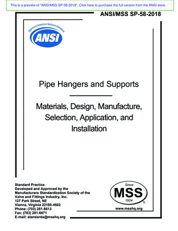
Digit 1Digit 2Digit 3 4Digit 5Digit 6SupplementInsulationThicknessDensityProduct GroupDesignPipe DiameterCradleLength56 Rest- &Guide Support01 21.3mm3 150mm0 25mm-1607 Line StopSupport02 26.9mm5 300mm1 40mm-22403 33.7mm7 500mm2 50mm-32005 48.3mm8 750mm3 80mm06 60.3mm4 100mm09 88.9mm5 130mm11 114.3mm6 150mm17 168.3mm7 180mm22 219.1mm8 200mm27 273.0mm9 250mm32 323.9mm36 355.6mm41 406.4mm46 457.2mm51 508.0mm56 558.8mm61 609.6mm66 660.4mmType Designation SystemAll cryogenic pipe supports can be clearlyidentified by code numbers. The 6 digitsplus density supplement contain all theinformation required. The code numbersystem facilitates the use of moderninformation technology and enables theunrestricted integration of the LISEGAmodular system into the current CADprograms.Example 1:5 6 51 7 4 - 224Density 224 kg/m3Insulation thickness100mmCradle length 500mmPipe Ø 508mmCryogenicsupport typeProduct group 571 711.2mm76 762.0mm81 812.8mm91 914.4mm97 965.2mmExample 2:5 6 51 7 4 G4 - 224Type 56 single clamp base rest- and guide pipe support.6Density 224 kg/m3Quadrupleclamp baseInsulation thickness100mmCradle length 500mmPipe Ø 508mmCryogenicsupport typeProduct group 5
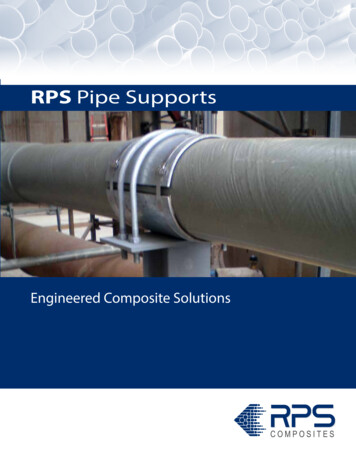
Double and Multiple Clamp BasePipe SupportsSpecial DesignnDouble clamp base cryogenic pipesupports or guided supports are requiredfor upward loads or high lateral loads.For this purpose the LISEGA cryogenicpipe supports can be extended as desired.nnEach variant is given a supplementarynumber after the 6th digit which describesthe type of guide. The pipe support can beordered in the following designs:G2A: Angulated clamp base pipe support(laterally guided)G2P: Double clamp base pipe supportG3: Triple clamp base pipe supportG4: Quadruple clamp base pipe supportType 56 as well as type 57 can be orderedwith these guide options. For example,type 57 can be used as a quadruplecryogenic pipe support in vertical piping.nnnnnType 56 double clamp base support for high upward loads.Special pipe sizes can also beaccommodated.For extremely large axial movements,special lengths can also be supplied.Use as a hanger (e.g. in combinationwith spring or constant hangers) is alsopossible. In this case the shoe of theclamp base is replaced by a specialpipe clamp, type 43. The clamp is thendesigned for the particular conditionsexisting in each case.Type 56 . .Deviations from the standard densitiesof the foam can be supplied, e.g. adensity of 120kg/m3.Slide bearings can be incorporated byfixing a polished stainless steel plateto the underside of the pipe shoe.Type 56 . . G2AFor special applications when increasedloads have to be absorbed, laminatedwood blocks can be utilized.The installation dimension 'E' can beadjusted if necessary. Increasing ordecreasing the E-dimension may affectthe design and the load capacity.Therefore, the actual operational loadshave to be provided in case of orderplacement.Type 56 . . G2PLISEGA takes pride in servicing theirclients and will gladly assist in anyspecial inquiry.Type 56 . . G3Type 56 . . G4Type designation system for doubleand multiple clamp base pipe supportsType 57 used as guided quadruple pipe support for verticalpipes with thrust rings to keep the support in place. Sameconfiguration but with additional lugs underneath the shoecan be used as a vertical line stop.Special articulated cryogenic horizontal hanger supportwith clamping mechanism.7
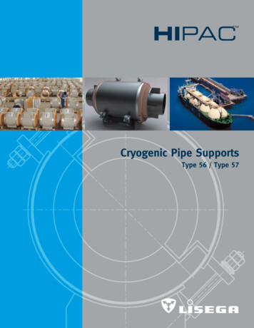
GUIDE SUPPORTSTYPE 56 01 .0 TO 56 97 .9The HIPAC range of supports is designed to operate attemperatures down to -196 C. Shrinkage in the pipe andHD-PUF is compensated by the disc spring clamping mechanism to prevent possible relative movement between theclamp base and the pipe. A maximum temperature differencefor each insulation thickness has been considered for theclamping force calculation. Therefore, the operating temperature of the piping system has to be provided with the order.a The maxiumum lateral and axial load is limited to 30% ofthe actual vertical load. For increased lateral loads or occasionalupward loads, multiple or double clamp bases should be used.For this purpose, the resulting load ( Fres FV2 FL2 ) must notexceed the maximum vertical load given in the selection tables.For higher axial loads type 57 can be used. In instances wherethere is axial movement, the load capacity of the support canonly be guaranteed if the center of the pipe shoe maintainscontact with the supporting structure. The design compressivestrength properties are based on a safety factor of 5.b The density is to be stated when ordering.c A stepping of 50mm on both side(s?) is also availableon request. If required, please provide according informationwith the order.C3C2C1metal protection shield C 50DCHEODtAA1Selection Table OD 21.3 - OD 26.9Type560130560150560131OD 21.3(ND 0254825D80560153OD 26.9(ND 0100150CC1cC2C3150250-300400150BMax. vertical load [kN] at density a bWeight [kg] at 2.14.37.6151618CC1cC2C3150250-300400150Max. vertical load [kN] at density a bWeight [kg] at 75.59.6151618
C3C2C1metal protection shield C 50DCHEDAtAA1Selection Table OD 33.7 - OD 60.3Type560330560350560331560351OD 33.7(ND 5Type560530560550560531560551OD 48.3(ND 5Type560630560650560631560651OD 60.3(ND 130150remarks see page 150200250CC1cC2C3150250-300400150BMax. vertical load [kN] at density a bWeight [kg] at 22427CC1cC2C3150250-300400150Max. vertical load [kN] at density a bWeight [kg] at .41019252730CC1cC2C3150250-300400150Max. vertical load [kN] at density a bWeight [kg] at 06.71323333641500600650700
Cryogenic Pipe Support Base / Design 5 Type Designation System 6 Double and Multiple Clamp Base Pipe Supports 7 Special Design 7 Type 56 01 .0 to 56 97 .9 8 . Type 57 01 .0 to 57 97 .9 19. Cryogenic Pipe Supports. Type 56 Rest- and Guide Supports / Type 57 Line Stop and Fixed Supports. 4. Supports for Cold and Cryogenic Applications. LISEGA offers a complete range of insula-ted cryogenic pipe .