Transcription
S7-200 SMART PIDConfiguration & PID TuneControlS7 - 200 SMART/ Version c/pages/default.aspxSiemensIndustryOnlineSupport
Legal informationLegal informationUse of application examplesApplication examples illustrate the solution of automation tasks through an interaction ofseveral components in the form of text, graphics and/or software modules. The applicationexamples are a free service by Siemens AG and/or a subsidiary of Siemens AG ("Siemens").They are non-binding and make no claim to completeness or functionality regardingconfiguration and equipment. The application examples merely offer help with typical tasks;they do not constitute customer-specific solutions. You yourself are responsible for the properand safe operation of the products in accordance with applicable regulations and must alsocheck the function of the respective application example and customize it for your system.Siemens grants you the non-exclusive, non-sub licensable and non-transferable right to havethe application examples used by technically trained personnel. Any change to the applicationexamples is your responsibility. Sharing the application examples with third parties or copyingthe application examples or excerpts thereof is permitted only in combination with your ownproducts. The application examples are not required to undergo the customary tests andquality inspections of a chargeable product; they may have functional and performancedefects as well as errors. It is your responsibility to use them in such a manner that anymalfunctions that may occur do not result in property damage or injury to persons. Siemens AG Copyright year All rights reservedDisclaimer of liabilitySiemens shall not assume any liability, for any legal reason whatsoever, including, withoutlimitation, liability for the usability, availability, completeness and freedom from defects of theapplication examples as well as for related information, configuration and performance dataand any damage caused thereby. This shall not apply in cases of mandatory liability, forexample under the German Product Liability Act, or in cases of intent, gross negligence, orculpable loss of life, bodily injury or damage to health, non-compliance with a guarantee,fraudulent non-disclosure of a defect, or culpable breach of material contractual obligations.Claims for damages arising from a breach of material contractual obligations shall however belimited to the foreseeable damage typical of the type of agreement, unless liability arises fromintent or gross negligence or is based on loss of life, bodily injury or damage to health. Theforegoing provisions do not imply any change in the burden of proof to your detriment. Youshall indemnify Siemens against existing or future claims of third parties in this connectionexcept where Siemens is mandatorily liable.By using the application examples, you acknowledge that Siemens cannot be held liable forany damage beyond the liability provisions described.Other informationSiemens reserves the right to make changes to the application examples at any time withoutnotice. In case of discrepancies between the suggestions in the application examples andother Siemens publications such as catalogs, the content of the other documentation shallhave precedence.The Siemens terms of use (https://support.industry.siemens.com) shall also apply.Security informationSiemens provides products and solutions with Industrial Security functions that support thesecure operation of plants, systems, machines and networks.In order to protect plants, systems, machines and networks against cyber threats, it isnecessary to implement – and continuously maintain – a holistic, state-of-the-art industrialsecurity concept. Siemens’ products and solutions constitute one element of such a concept.Customers are responsible for preventing unauthorized access to their plants, systems,machines and networks. Such systems, machines and components should only be connectedto an enterprise network or the Internet if and to the extent such a connection is necessaryand only when appropriate security measures (e.g. firewalls and/or network segmentation)are in place.For additional information on industrial security measures that may be implemented, pleasevisit ’ products and solutions undergo continuous development to make them moresecure. Siemens strongly recommends that product updates are applied as soon as they areavailable and that the latest product versions are used. Use of product versions that are nolonger supported, and failure to apply the latest updates may increase customer’s exposure tocyber threats.To stay informed about product updates, subscribe to the Siemens Industrial Security RSSFeed at: https://www.siemens.com/industrialsecurity.S7 – 200 Smart PIDEntry-ID: 3, V0.0, 06/20192
Table of contentsTable of contents Siemens AG Copyright year All rights reservedWarranty and liability . 21Introduction . 41.11.21.3Overview . 4Mode of operation . 4Components used . 42Engineering . 62.12.22.32.3.12.3.22.3.32.4Description of interface . 6Project integration . 6Operation . 8PID Wizard Programming Steps . 8PLC Programming . 19PID Auto-Tune and PID Tune Control Panel . 25Error handling . 283Operation of the application example . 293.13.1.13.1.23.1.33.1.43.1.53.1.6Overview . 29Overview(Start Screen) . 30Trend View . 31Monitoring. 32Configuration . 33Simulation. 34Settings . 354Appendix . 364.14.24.34.4Service and Support . 36Support . 37Links and Literature . 37Change documentation . 37S7 – 200 Smart PIDEntry-ID: 3, V0.0, 06/20193
1 Introduction1Introduction1.1OverviewPID Auto-Tune capability has been incorporated into the S7-200 smart PLC andSTEP-7 Micro/WIN has added a PID Tuning Control Panel. Together, these twofeatures greatly enhance the utility and ease of use of the PID function.Auto-tune can be initiated by the user program from an operator panel or by thePID Tuning Control Panel. PID loops can be auto-tuned one at a time or all eight loopscan be auto-tuned at the same time if necessary. The PID Auto-Tune computessuggested (near optimum) values for the gain, integral time (reset) and derivative time(rate) tuning values. It also allows you to select tuning for fast, medium, slow or veryslow response of your loop. Siemens AG Copyright year All rights reservedWith the PID Tuning Control Panel you can initiate the auto-tuning process,abort the auto-tuning process and monitor the results in a graphical form. The controlpanel displays any error conditions or warnings that might be generated. It also allowsyou to apply the gain, reset and rate values computed by auto-tune.1.2Mode of Operationa.Proportional ControlA proportional controller will have the effect of reducing the rise time and will reduce, butnever eliminate the steady state error.b.Integral ControlAn integral control will have the effect of eliminating the steady state error, but it maymake the transient response worse.c.Proportional & Integral (P-I) ControlA PI controller could improve relative stability and eliminate steady state error at thesame time, but the settling time is increased.d.Proportional & Derivative (P-D) ControlA PD controller could add damping to a system, but the steady-state response is notaffected.(steady state error is not eliminated).e.Proportional , Integral & Derivative (P-I-D) ControlA PID controller removes steady-state error and decreases system settling times whilemaintaining a reasonable transient response.1.3Components usedThis application example has been created with the following components:Table 1-1ComponentNumberArticle numberCPU ST6016ES7 288-1ST60-0AA0STEP 7-MicroWINSMART V2.416ES7 288-SW01-0AA0TIA PORTAL V15.116ES7 822-1AA05-0YA7Basic HMI KTP900 PN16AV2 123-2JB03-0AX0S7 – 200 Smart PIDEntry-ID: 3, V0.0, 06/2019Note4
1 IntroductionThis application example consists of the following components:Table 1-2File nameNote Siemens AG Copyright year All rights reservedComponentS7 – 200 Smart PIDEntry-ID: 3, V0.0, 06/20195
2 Engineering2Engineering2.1Description of interface Siemens AG Copyright year All rights reservedLAD / FBDSTLDescriptionPID TBL, LOOPThePID loop instruction (PID)executes a PID loopcalculationonthereferenced LOOP basedupontheinputandconfiguration information inTable (TBL).The PID loop instruction (Proportional, Integral, and Derivative Loop) isprovided to perform the PID calculation. The top of the logic stack (TOS) must be ON(power flow) to enable the PID calculation. The instruction has two operands: a tableaddress which is the starting address of the loop table and a LOOP number which is aconstant from 0 to 7. Eight PID instructions can be used in a program. If two or morePID instructions are used with the same loop number (even if they have different tableaddresses), the PID calculations will interfere with one another and the output will beunpredictable. The loop table stores nine parameters used for controlling andmonitoring the loop operation and includes the current and previous value of theprocess variable, the set point, output, gain, sample time, integral time (reset),derivative time (rate), and the integral sum (bias). STEP 7-Micro/WIN SMART offers thePID wizard to guide you in defining a PID algorithm for a closed-loop control process.Select the "Instruction wizard" command from the "Tools" menu and then select "PID"from the "Instruction wizard" window.2.2Project integrationLAD/FBDSTLDescriptionPID0 CTRLThe PIDx CTRL instruction executesthe PID function based on the inputsand outputs you enter in the PIDWizard. It is called every scan.PID Scale,Setpoint, AutoManual, ManualOutput Value, PIDOutNote: The inputs and outputs for thePIDx CTRL instruction depend onthe choices you make in the wizard.For example, if you select to EnableLow Alarm (PV) on the Loop AlarmOptions screen of the wizard, thenthe Low Alarm output displays in theinstruction.In automatic mode, calculations willbe performed using the built-in PIDalgorithm to drive the "Output" of thePIDx CTRL box. In manual mode,the "Output" is controlled by the"Manual Output" input.If the checkbox in the wizard on thenext-to-last screen is checked to"Add Manual Control of the PID",then the PIDx CTRL instruction willcontain the input parameters "AutoS7 – 200 Smart PIDEntry-ID: 3, V0.0, 06/20196
2 Engineering Siemens AG Copyright year All rights reservedManual" and "Manual Output".Otherwise, these two inputs will notappearonthePIDx CTRLinstruction, and automatic mode isenabled.When used, the "Auto Manual"Boolean input must be ON for automode control, and off for manualmode control. When the PID is inmanual mode, the "Output" (of thePIDx CTRL instruction) is controlledby writing a normalized real value(0.00 - 1.00) to the "Manual Output"input, driving the "Output" betweenthe range values assigned in thewizard for the "Output". For example,if in the wizard you set the "Output"range to be from 2000 to 26000, thenwhen the "Manual Output" input is at0.00, the "Output" should be at 2000.Similarly, when the "Manual Output"input is at 1.00, the "Output" shouldbe at 26000. When the "ManualOutput" input is at 0.50, the "Output"should be halfway through its range,or in this case, (26000-2000)/2 2000 14000.PIDx CTRL subroutine parametersInputs/OutputsOperandsData typesPV IVW, IW, QW, MW, SW, SMW, LW,T, C, AIW, AC, *VD, *LD, *ACINTSet point RID, QD, MD, SD, SMD, VD, LD, AC,Constant, *VD, *LD, *ACREALAuto ManualI, Q, M, SM, T, C, V, S, LBOOLManual OutputID, QD, MD, SD, SMD, VD, LD, AC,Constant, *VD, *LD, *ACREALOutput (Analog)IW, QW, MW, SW, SMW, T, C, VW,LW, AIW, AC, Constant, *VD,*LD,*ACINTOutput (Digital), HighAlarm, Low Alarm,Module ErrI, Q, M, SM, T, C, V, S, LBOOLS7 – 200 Smart PIDEntry-ID: 3, V0.0, 06/20197
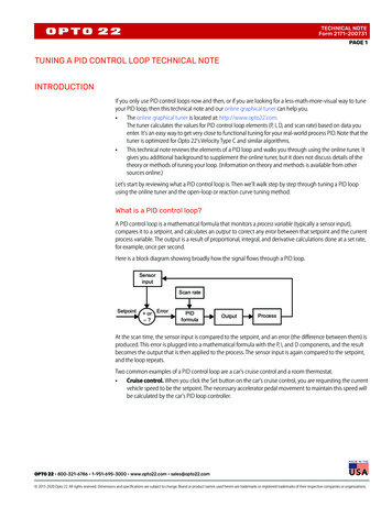
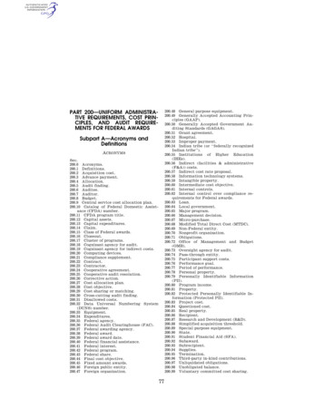
2 Engineering2.3Operation2.3.1PID Wizard Programming StepsUse one of the following methods to open the PID Wizard: Select the PID Wizard from the Tools menu in Micro/WIN SMART :Figure 1. Select the PID Wizard Open the "Wizard" folder in the project tree and double-click "PID" or select "PID" and Siemens AG Copyright year All rights reservedpress the Enter key.Figure 2. Select PID WizardsS7 – 200 Smart PIDEntry-ID: 3, V0.0, 06/20198
2 EngineeringStep 1: Define the PID loop number Siemens AG Copyright year All rights reservedTo be configured in this dialog box, select the loop to be configured. Up to 8 loops canbe configured. When you select a loop on this dialog, the tree view on the left side ofthe PID wizard is updated with all the nodes required to configure the loop.Figure 3. Select the loop you need to configureS7 – 200 Smart PIDEntry-ID: 3, V0.0, 06/20199
2 Engineering Siemens AG Copyright year All rights reservedStep 2: Name the loop configurationWe can configure a custom name for the loop. The default name for this section is "loopx", where "x" is equal to the loop number.Figure 4. Name the PID loopS7 – 200 Smart PIDEntry-ID: 3, V0.0, 06/201910
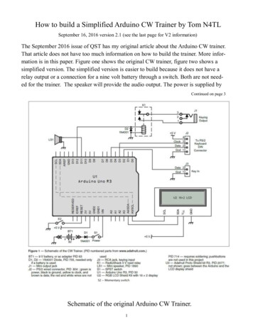
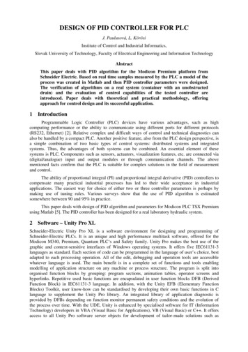
2 Engineering Siemens AG Copyright year All rights reservedStep 3: Set the PID loop parametersFigure 5. Set the PID parametersThe PID loop parameters are defined in Fig. 5 and should be real number.a.Gain : The proportional constant, default 1.00.b.Integration time : If you do not want the integral action, you can set the value verylarge (such as 10000.0), the default value 10.00.c.Derivative time : If you do not want a differential loop, you can set the derivative time to0 and the default value 0.00.d.Sampling time : It is the time interval between the PID control loop sampling andrecalculating the output value. The default value is 1.00. After the wizard is completed, ifyou want to modify this number, you must return to the wizard to modify it, and youcannot modify it in the program or in the status table.S7 – 200 Smart PIDEntry-ID: 3, V0.0, 06/201911
2 Engineering Siemens AG Copyright year All rights reservedStep 4: Set the loop process variableFigure 6. Set the PID input process variablea.Specifies how the loop process variable (PV) is calibrated. You can choose from thefollowing options: Unipolar: the input signal is positive, such as 0-10V or 0-20mA. Bipolar: The input signal varies from negative to positive. If the input signal is 10V, 5V, etc. Select 20% offset: If the input is 4-20mA, select the single polarity and this item, 4mAis 20% of the 0-20mA signal, so choose 20% offset, that is, 4mA corresponds to 5530,20mA corresponds to 27648.b.Feedback input value range: When a. is set to unipolar, the default value is 0 - 27648, corresponding to the inputrange 0 - 10V or 0 - 20mA, etc., the input signal is positive. When a. is set to bipolar, the default value is -27648 - 27648, and the correspondinginput range can be 10V, 5V, etc. depending on the range. When a. Select 20% offset, the value range is 5530 - 27648, which cannot be changed.c.In the "Scaling" parameter, specify how the loop setpoint (SP) is scaled. The default is areal number between 0.0 and 100.0.S7 – 200 Smart PIDEntry-ID: 3, V0.0, 06/201912
2 Engineering Siemens AG Copyright year All rights reservedStep 5: Set the input loop output optionsFigure 7. Set the PID output options.a.Output Type:You can select either an analog output or a digital output. The analog output isused to control some equipment that requires analog quantity, such as proportionalvalve, frequency converter, etc.; digital output is actually the on/off state of the controloutput point according to a certain duty cycle change, which can control the solid staterelay (Heating rod, etc.).b. To select the analog quantity, you need to set the range of the loop output variablevalue. You can choose:Unipolar : unipolar output, can be 0-10V or 0-20mA, etc.Bipolar : bipolar output, can be positive or negative 10V or positive and negative 5V,etc.Unipolar 20% offset : If the 20% offset is selected, the output is 4 - 20mA.c. Ranges:When c is unipolar, the default is 0 to 27648.When c is bipolar, the value is -27648 to 27648.When c is 20% offset, the value is 5530 - 27648, which cannot be changed. S7 – 200 Smart PIDEntry-ID: 3, V0.0, 06/201913
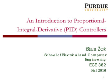
2 Engineering Siemens AG Copyright year All rights reservedStep 6: Set the loop alarm optionFigure 8. Set the loop alarm limit valueThe wizard provides three outputs to reflect low value alarms for process values(PV), high value alarms, and process value analog module error status. The output isset to 1 when the alarm condition is met. These features work after the correspondingselection box is selected.a.Enable the low value alarm and set the low value of the process value (PV) alarm. Thisvalue is the percentage of the process value. The default value is 0.10, that is, the lowvalue of the alarm is 10% of the process value. This value can be set to a minimum of0.01, which is 1% of full scale.b.Enable the high value alarm and set the high value of the process value (PV) alarm.This value is the percentage of the process value. The default value is 0.90, that is, thehigh value of the alarm is 90% of the process value. This value can be set to amaximum of 1.00, which is 100% of full scale.c.Enable the process value (PV) analog module error alarm and set the module locationwhere the module is connected when the CPU is connected. "EM0" is the location ofthe first expansion module.S7 – 200 Smart PIDEntry-ID: 3, V0.0, 06/201914
2 Engineering Siemens AG Copyright year All rights reservedStep 7: Define the PID initialization subroutine and interrupt program name andhand/auto mode generated by the wizardFigure 9. Specify the subroutine, interrupt service program name, and select manualcontrol.a.Specify the PID name of the initial subroutine.b.Specify the name of the PID interrupt subroutine.c.Here you can choose to add the PID manual control mode. In the PID manual controlmode, the loop output is controlled by the manual output setting. At this time, themanual control output parameter needs to be written with a real number of 0.0-1.0,representing 0%-100% of the output instead of directly changing the output value.S7 – 200 Smart PIDEntry-ID: 3, V0.0, 06/201915
2 Engineering Siemens AG Copyright year All rights reservedStep 8: Specify the PID operation data storage areaFigure 10. Assign the operation data storage area.The PID instruction (function block) uses a 120-byte V-zone parameter table forthe operation of the control loop; in addition, the standardized program of theinput/output quantities generated by the PID wizard also requires the arithmetic datastorage area. You need to define a starting address for them, and make sure that thefirst few bytes of the address are not reused elsewhere in the program.Note:If you click "Suggest", the wizard will automatically set the V area address that hasnot been used in the current program.S7 – 200 Smart PIDEntry-ID: 3, V0.0, 06/201916
2 Engineering Siemens AG Copyright year All rights reservedStep 9: Generate PID subroutine, interrupt program and symbol table.Figure 11. Generate PID subroutine, interrupt routine, symbol table, etc.Step 10: After configuring the PID wizard, you need to call the PID subroutinegenerated by the wizard in the program (as shown below).Figure 12. PID subroutineS7 – 200 Smart PIDEntry-ID: 3, V0.0, 06/201917
2 EngineeringFigure 13. Calling the PID subroutine Siemens AG Copyright year All rights reservedWhen the PID subroutine is called in the user program, the PID subroutinegenerated by the wizard can be double-clicked in the block of the instruction tree. In thelocal variable table, the interpretation and value range of the formal parameters can beseen.a.The PIDx CTRL subroutine must be enabled with SM0.0. No other conditions can beconcatenated after SM0.0, and there must be no jumps over it. If the PIDx CTRLsubroutine is called in a subroutine, the subroutine calling it must also Use only SM0.0calls to keep it up and running.b.Enter the process value or analog value (feedback) here.c.Enter the set value variable address (VDxx) here, or directly input the set valueconstant. According to the setting in the wizard, 0.0-100.0, you should enter a realnumber of 0.0-100.0.d.Here V20.0 is used to control the PID hand/auto mode. When V20.0 is 1, it is automatic,and it is output from VW18 through PID operation. When V20.0 is 0, PID will stopcalculation, and output is ManualOutput. This item does not appear if the PID manualfunction is not selected in the wizard.e.Here you can enter the variable address (VDxx) of the manual setpoint or enter thenumber directly. The value range is a real number between 0.0 and 1.0, representingthe percentage of the output range. Example: If you enter 0.5, set it to 50% of theoutput. This item does not appear if the PID manual function is not selected in thewizard.f.Type the output address of the control amount here.g.When the high alarm condition is met, the corresponding output is set to 1. If the highalarm function is not enabled in the wizard, this item will not appear.h.When the low alarm condition is met, the corresponding output is set to 1. If the lowalarm function is not enabled in the wizard, this item will not appear.S7 – 200 Smart PIDEntry-ID: 3, V0.0, 06/201918
2 Engineering2.3.2PLC ProgrammingMain Program Block Siemens AG Copyright year All rights reservedNetwork 1: Scale Analog input with Input Min/Max Count (ISH & ISL) and OutputMax / Min Range (OSH/OSL). Real Output converted to Int format for Provide PIDPV.Network 2: Initialize and monitor PID block by calling PID0 CTRL.S7 – 200 Smart PIDEntry-ID: 3, V0.0, 06/201919
2 EngineeringNetwork 3: PID output Integer is converted to Real for tuning display. Siemens AG Copyright year All rights reservedNetwork 4: PID Output Move to Analog Output.Network 5 & 6: High Alarm and Low Alarm Logic.S7 – 200 Smart PIDEntry-ID: 3, V0.0, 06/201920
2 EngineeringNetwork 7: Call Auto Tune Subroutine. Siemens AG Copyright year All rights reservedNetwork 8: PLC ON and OFF Logic.S7 – 200 Smart PIDEntry-ID: 3, V0.0, 06/201921
2 EngineeringAI Scale Subroutine Logic Siemens AG Copyright year All rights reservedNetwork 1 & 2: Output [(OSH - OSL) * (Input - ISL) / (ISH - ISL)] OSLS7 – 200 Smart PIDEntry-ID: 3, V0.0, 06/201922
2 EngineeringAuto Tune SubroutineNetwork 1: Update Manual Enable Gain Value to PLC Siemens AG Copyright year All rights reservedNetwork 2: Update Manual Enable Int. time Value to PLCNetwork 3: Update Manual Enable Derivative time Value to PLCS7 – 200 Smart PIDEntry-ID: 3, V0.0, 06/201923
2 EngineeringNetwork 4: Gain value determined by Auto Tune algorithm. Siemens AG Copyright year All rights reservedNetwork 5: Integral time value determined by Auto Tune algorithm.Network 6: Deviation value calculated by algorithm if automatic calculation optionsetS7 – 200 Smart PIDEntry-ID: 3, V0.0, 06/201924
2 Engineering2.3.3PID Auto-Tune and PID Tune Control PanelThe PID Auto-Tuner is capable of determining suggested tuning values for bothdirect-acting and reverse-acting P, PI, PD, and PID loops.The purpose of the PID Auto-Tuner is to determine a set of tuning parametersthat provide a reasonable approximation to the optimum values for your loop. Startingwith the suggested tuning values will allow you to make fine tuning adjustments andtruly optimize your process. Siemens AG Copyright year All rights reservedAuto-Hysteresis and Auto-DeviationThe hysteresis parameter specifies the excursion (plus or minus) from set pointthat the PV (process variable) is allowed to make without causing the relay controller tochange the output. This value is used to minimize the effect of noise in the PV signal tomore accurately determine the natural oscillation frequency of the process. If you selectto automatically determine the hysteresis value, the PID Auto-Tuner will enter ahysteresis determination sequence. This sequence involves sampling the processvariable for a period of time and then performing a standard deviation calculation on thesample results.In order to have a statistically meaningful sample, a set of at least 100 samplesmust be acquired. For a loop with a sample time of 200 msec, acquiring 100 samplestakes 20 seconds. For loops with a longer sample time it will take longer. Even though100 samples can be acquired in less than 20 seconds for loops with sample times lessthan 200 msec, the hysteresis determination sequence always acquires samples for atleast 20 seconds.Once all the samples have been acquired, the standard deviation for the sampleset is calculated. The hysteresis value is defined to be two times the standard deviation.Auto-Tuning SequenceThe auto-tuning sequence begins after the hysteresis and deviation values havebeen determined. The tuning process begins when the initial output step is applied tothe loop output. This change in output value should cause a corresponding change inthe value of the process variable. When the output change drives the PV away from setpoint far enough to exceed the hysteresis boundary a zero-crossing event is detectedby the auto-tuner. Upon each zero crossing events the auto-tuner drives the output inthe opposite direction.The tuner continues to sample the PV and waits for the next zero crossingevents. A total of twelve zero-crossings are required to complete the sequence. Themagnitude of the observed peak-to-peak PV values (peak error) and the rate at whichzero-crossings occur are directly related to the dynamics of the process.Early in the auto-tuning process, the output step value is proportionally adjustedonce to induce subsequent peak-to-peak swings of the PV to more closely match thedesired deviation amount. The auto-tuning sequence will be terminated with an error, ifthe time between zero crossings exceeds the zero-crossing watchdog interval time. Thedefault value for the zero-crossing watchdog interval time is two hours.S7 – 200 Smart PIDEntry-ID: 3, V0.0, 06/201925
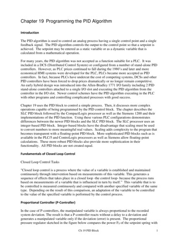
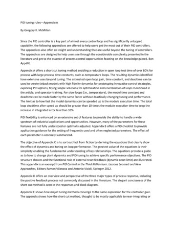
2 EngineeringPID Tuned Control Panel Siemens AG Copyright year All rights reserved The PID control panel includes the following fields:Current values: The values of the SP (Set point), PV (Process Variable), OUT (Output),Sample Time, Gain, Integral time, and Derivative time are displayed. The SP, PV, OUTis shown in green, red, and blue, respectively; the same color legend is used to plot thePV, SP, and OUT values.Graphical display: The graphical display shows color-coded plots of the PV, SP, andOutput as a function of time. The PV and SP share the same vertical scale which islocated at the left-hand side of the graph while the vertical scale for the output is locatedon the right-hand side of the graph.Tuning Parameters: At the bottom left-hand side of the screen are the TuningParameters (Minutes). Here, the Gain, Integral Time, and Derivative Time values aredisplayed. You click in the "Calculated" column to modify any one of the three sourcesfor these values."Update CPU" button: You can use the" Update CPU" button to transfer the displayedGain, Integral Time, and Derivative Time values to the CPU for the PID loop that isbeing monitored. You can use the "Start" button to initiate an auto-tuning sequence.Once an auto-tuning sequence has started, the "Start" button becomes a "Stop" button.S7 – 200 Smart PIDEntry-ID: 3, V0.0, 06/201926
Siemens AG Copyright year All rights reserved2 EngineeringS7 – 200 Smart PIDEntry-ID: 3, V0.0, 06/201927
2 EngineeringError handlinga.A compile error occured, check non-fatal errors for more information. For resolving this type of error change your Region and Language in control panel andrestart your computer and download.b.This POU contains one or more invalid references to parameterized subroutines. For resolving this, delete present PID block and add new one. Siemens AG Copyright year All rights reserved2.4S7 – 200 Smart PIDEntry-I
STEP-7 Micro/WIN has added a PID Tuning Control Panel. Together, these two features greatly enhance the utility and ease of use of the PID function. . STEP 7-MicroWIN SMART V2.4 1 6ES7 288-SW01-0AA0 TIA PORTAL V15.1 1 6ES7 822-1AA05-0YA7 Basic HMI KTP900 PN 1 6AV2 123-2JB03-0AX0 . 1 Introduction S7 - 200 Smart PID