Transcription
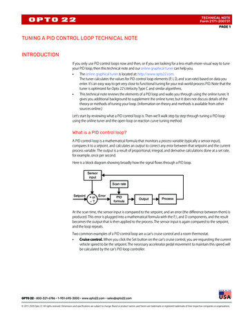
Chapter 19 Programming the PID AlgorithmIntroductionThe PID algorithm is used to control an analog process having a single control point and a singlefeedback signal. The PID algorithm controls the output to the control point so that a setpoint isachieved. The setpoint may be entered as a static variable or as a dynamic variable that iscalculated from a mathematical operation.For many years, the PID algorithm was not accepted as a function suitable for a PLC. It wasincluded in a DCS (Distributed Control System) or configured from a number of stand-alone PIDcontrollers. However, as PLC prices continued to fall during the 1980’s and later and moreeconomical HMI systems were developed for the PLC, PLCs became more accepted as PIDcontrollers. In fact, because PLCs have undercut the cost of competing systems, DCSs and otherPID controllers have been forced to drop prices dramatically or no longer remain competitive.An early hybrid design was introduced into the Allen-Bradley 1771 I/O family including 2 PIDstand-alone controllers attached to a single I/O slot and executing the PID algorithm from thecontroller in the I/O slot. Newer control schemes have the PID algorithm executing in the PLCwith other programs and controlling complicated processes with good success.Chapter 19 uses the PID block to control a simple process. Then, it discusses more complexoperations capable of being programmed by the PID control block. The chapter describes theSLC PID block followed by the CompactLogix processor as well as the Siemens 1200 and theirimplementations of the PID function. Using these various PLC configurations demonstratesdifferences between the newer PID blocks and the SLC PID block. The SLC processor uses aninteger-based PID block. Integer-based blocks have the disadvantage that scaling must be usedto convert numbers to more meaningful real values. Scaling adds complexity to the program thatbecomes transparent with a floating-point PID block. More sophisticated PID blocks such as isavailable in the PLC/5 and ControLogix processors as well as Siemens allow floating-pointcalculations. These more robust PID blocks also provide more sophistication in theirfunctionality. All PID blocks are not created equal.Fundamentals of Closed Loop ControlClosed Loop Control Tasks"Closed loop control is a process where the value of a variable is established and maintainedcontinuously through intervention based on measurements of this variable. This generates asequence of effects that takes place in a closed loop -the control loop- because the process runsbased on measurements of a variable that is influenced in turn by itself.” This variable that is tobe controlled is measured continuously and compared with another specified variable of the sametype. Depending on the result of this comparison, an adaptation of the variable to be controlledto the value of the specified variable is performed by the control process.Proportional Controller (P-Controller)In the case of P-controllers, the manipulated variable is always proportional to the recordedsystem deviation. The result is that a P-controller reacts without a delay to a deviation andgenerates a manipulated variable only if the deviation (error) is present. The proportionalpressure regulator sketched in the figure below compares the power FS of the setpoint spring withCh 19 PID Block1
the power FB that the pressure P2 generates in the spring-elastic metal bellows. If the forces areoff balance, the lever rotates around the pivot point D. The valve position changes andaccordingly the pressure P2 to be regulated until a new balance of forces is established.The behavior of the P-controller if a system deviation suddenly occurs is shown in the figurebelow. The amplitude of the manipulated variable jump y depends on the level of the deviation eand the amount of the proportional coefficient Kp:To keep the deviation low, a proportionality factor as large as possible has to be selected.Increasing the factor causes the controller to respond faster. However, a value that is too highmay cause overshooting and a large hunting tendency on the part of the controller.Metal bellowsSetpoint springFig. 19-1𝐴𝑐𝑡𝑢𝑎𝑙 𝐹𝑙𝑜𝑤 𝑃2 𝑃1𝑒(𝑒𝑟𝑟𝑜𝑟) 𝐹𝑙𝑜𝑤 (𝐴𝑐𝑡𝑢𝑎𝑙) 𝐹𝑙𝑜𝑤 (𝑆𝑒𝑡 ) 𝐾𝑝 𝑒The diagram below shows the behavior of the lvalueFig. 19-2timeCh 19 PID Block2
The advantages of this type of controller consist on the one hand of its simplicity (electronicimplementation can, in the simplest case, consist of merely a resistor), and on the other hand itsprompt response in comparison to other controller types. The main disadvantage of the Pcontroller is the continuous deviation; the setpoint is never completely attained, even long term.This disadvantage as well as the not yet ideal response speed can be minimized onlyinsufficiently with a larger proportionality factor, since otherwise the controller will overshoot.In the most unfavorable case, the controller will enter a state of continuous oscillation. Thiscauses the controlled variable to be periodically moved away from the setpoint, not by theinfluencing variable but by the controller.The problem of continuous deviation is solved best with an integral controller.Integral Controller (I-Controller)Integrating controllers are used to completely correct system deviations at each operating point.As long as the deviation is unequal to zero, the manipulated variable continues to change. Onlywhen the reference variable and the controlled variable are equal is the control system in a steadystate.The mathematical formulation of this integral behavior is as follows:𝑦 𝐾𝑖 () 𝑤𝑖𝑡ℎ 𝐾𝑖 1𝑇𝑛How fast the manipulated variable rises (or falls) depends on the deviation and the integrationtime.Fig. 19-3Block diagramPI-ControllerThe PI-controller is a type often used in practice. It results from connecting a P-controller and anI-controller in parallel. When laid out correctly it unites the advantages of both controller types(stable and fast, no permanent system deviation), so that their disadvantages are compensated atthe same time.Ch 19 PID Block3
Block diagramFig. 19-4The behavior with respect to time is identified by the proportional coefficient Kp and the resettime Tn. Because of the proportional component, the manipulated variable responds immediatelyto every system deviation e, while the integral component takes effect only in the course of time.Tn represents the time that passes until the I-component generates the same amplitude of flow asoccurs immediately because of the P-component (Kp). As in the case of the I-controller, the resettime Tn has to be decreased if we want to increase the integral component.Differential Controller (D-Controller)The D-controller generates its manipulated variable from the rate of change of the systemdeviation, and not, as the P-controller, from its amplitude. For that reason, it respondsconsiderably faster than the P-controller. Even if the deviation is small, it generates (lookingahead) large amplitudes of flow as soon as an amplitude change occurs. However, the Dcontroller does not detect permanent deviations, because no matter how large it is, its rate ofchange equals zero. For that reason, the D-controller is used only rarely by itself in practice.Rather, it is used jointly with other control elements, usually in connection with a proportionalcomponent.PID ControllerIf we expand the PI controller with a D-component, the universal PID controller is created. As inthe case of the PD controller, adding the D-component has the effect that, if laid out correctly,the controlled variable reaches its setpoint sooner and its steady state faster.Ch 19 PID Block4
𝑑𝑒𝑦 𝐾𝑝 𝑒 𝐾𝑖 𝑒 𝑑𝑡 𝐾𝐷 𝑑𝑡Fig. 19-5with𝐾𝑖 𝐾𝑝𝑇𝑛, 𝐾𝐷 𝐾𝑝 𝑇𝑣PID Diagrams and EquationsObjectives of Control System SettingFor the control result to be satisfactory, selecting a suitable controller is an important aspect.However, even more important is setting the suitable controller parameters Kp, Tn and Tv, thathave to be adjusted to the controlled system behavior. Usually, we have to compromise betweena very stable but slow control system or a very dynamic, more unsettled control performancewhich under certain circumstances has a tendency to oscillate and can become unstable.In the case of non-linear systems that are always to process at the same operating point-such as fixed setpoint control- the controller parameters have to be adjusted to the controlledsystem behavior at this working point. If, as in the case of servo controls, a fixed working pointcannot be defined, a controller setting has to be found that supplies a sufficiently fast and stablecontrol result over the entire working range.In practice, controllers are usually set based on values arrived at through experience. If these arenot available, the controlled system behavior has to be analyzed exactly, in order to subsequently-with the aid of theoretical or practical layout procedures - specify suitable controller parameters.Ch 19 PID Block5
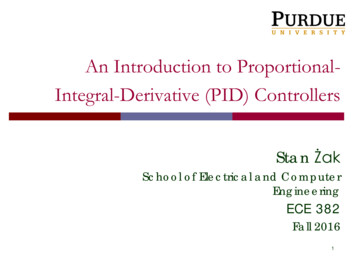
An Example SLC PID FunctionIn its simplest form, the SLC PID block is used as a single block with no input contacts andsurrounded by only two SCP blocks. This PID instruction is located in Ladder 2. The SCP blockis configured to retrieve a numerical value from the analog input channel, linearly scale the inputand move the resultant value to the PID block. The input is a 4-20 mA signal from a flowtransmitter. The output is a 4-20 mA signal to a variable flow valve.SCP – Scale with ParametersInputInput MinInput MaxScaled MinScaled MaxOuptutPIDControl BlockProcess VariableControl VariableControl Block LengthSCP – Scale with ParametersInputInput MinInput MaxScaled MinScaled MaxOutputFig. 19-6Simple Program of PID for SLC ProcessorCh 19 PID Block6
In the first SCP instruction, values found in the Input Min and Input Max of the SCP instructionare from the I/O card. The engineer must first decide which I/O card to use and then find theproper lower and upper limits from the literature on the card to enter values in the SCPinstruction.In this case, the analog card selected is the 1746-NIO4I Ser. A. This card is a combination cardwith 2 analog inputs and 2 analog outputs. From the web, select I/O Analog Modules, AnalogI/O Modules for SLC 500 Programmable Controllers – Technical Data. Then select 4 ChannelModule Configuration, 4 Channel Module Wiring, and 4 Channel Module Specifications to findthe choices available for Analog Inputs and Analog Outputs.In the section describing 4 Channel Module Specifications are found the following Channel Datasheets:Input Type /- 10 Vdc0 to 5V dc1 to 5V dc0 to 10 Vdc0 to 20 mA4 to 20 mA /- 20 mA0 to 1 mASignal Range-10.25 to 10.25 Vdc-0.5 to 5.5 Vdc0.5 to 5.5 Vdc-0.5 to 10.25 Vdc-0.5 to 20.5 mA3.5 to 20.5 mA-20.5 to 20.5 mA-0.05 to 1.05 mAEngineering Units-10250 to 10250-500 to 5500500 to 5500-500 to 10250-500 to 205003500 to 20500-20500 to 20500-50 to 1050EU Scale1 mV/step1 mV/step1 mV/step1 mV/step1.0 uA/step1.0 uA/step1.0 uA/step1.0 uA/stepChannel Data Word Values for Engineering UnitsInput Type /- 10Vdc0 to 5Vdc1 to 5 Vdc0 to 10 Vdc0 to 20 mA4 to 20 mA /- 20 mA0 to 1 mASignal Range-10.00 to 10.00 Vdc0.0 to 5.00 Vdc1.00 to 5.00 Vdc0.0 to 10.00 Vdc0.0 to 20.0 mA4.0 to 20.0 mA-20.0 to 20.0 mA0.0 to 1.00 mANI4 Data Format-32768 to 327670 to 163843277 to 163840 to 327670 to 163843277 to 16384-16384 to 163840 to 1000Channel Data Word Values for Scaled DataUsing the value 4 to 20 mA from the Input Type column, the value in Engineering Units is 3277min to 16384 max. These values are entered in the SCP instruction to scale the variablescorrectly.Fig. 19-7SCP – Scale with ParametersInputInput Min3277Input Max16384Scaled MinScaled MaxOuptutThe scaled min and max values that are sent to the PID’s process variable are found in the setupdocumentation of the PID block. The min value is 0 and the max value is 16383. A locationmust be selected. In this case, the process variable or PV is selected to be N10:28. It isCh 19 PID Block7
advisable to keep the PID block data separated from other integer data. In order to do keep thedata for the PID separated, the data file N10 was created to handle the PID data.The input address may also be selected. Remember the value is I:s.w where s is the slot numberand w is the relative word address down the card. In this case, the slot address chosen is 1 andthe w or word address is 0, the first analog input point on the card. The other option for the inputin slot 1 is I:1.1.SCP – Scale with ParametersInputI:1.0Input Min3277Input Max16384Scaled Min0Scaled Max16383OutputN10:28PIDControl BlockProcess VariableN10:28Control VariableControl Block Length23Fig. 19-8Moving the Process Variable into the PID BlockThe control block address is chosen. This address requires 23 contiguous words reserved in aninteger table. The block N10:0 (through N10:22) was chosen. Also reserve a location for thecontrol variable or output of the PID function. N10:29 was chosen.This control variable or output is then sent to the analog output card. Scaling again must bechosen. The min for the PID output is 0 and the max is 16383. These are the same values as areused for the PID input. To use the entire range of values for a PID input or output, choose therange 0 to 16383. Always strive to use the entire range of the PID block when programming aninteger PID block. This gives the greatest accuracy.The scaled output must be ranged to fit a 4 to 20 mA analog output card. Use the values as werefound in the reference manual, 6,242 min and 31,208 max. Use the first output point on the samecard as the input. Its slot number is O:1.0. Now, the PID and two SCP blocks can be finished.Ch 19 PID Block8
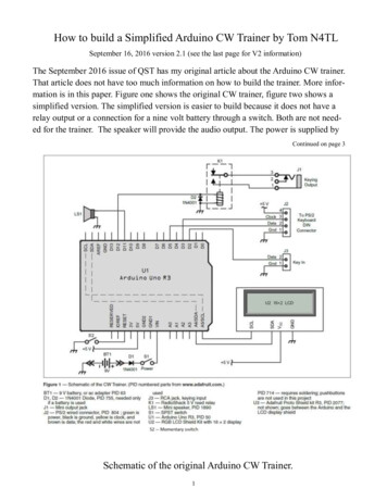
SCP – Scale with ParametersInputI:1.0Input Min3277Input Max16384Scaled Min0Scaled Max16383OutputN10:28PIDControl BlockProcess VariableN10:28Control VariableN10:29Control Block Length23SCP – Scale with ParametersInputN10:29Input Min0Input Max16383Scaled Min6242Scaled Max31208OutputO:1.1Fig. 19-9Moving the Variables Into and Out of the PIDWiring a 4-20 mA Current LoopHandling wiring and other hardware issues is found from information in the instruction manualfor the module. In the case above, the card used was the 1746-NI04I module from AllenBradley. Look specifically in the chapter on installation and wiring.In addition to the actual wiring diagram for the application, important information including dipswitch settings should be noted. If possible, all dip switch settings should be copied to theinstallation drawing for the card or added as notes to the schematic drawings. In the case of the1746-NI04I card, no dip switches were found.To wire a 4-20 mA control circuit for a PLC input, wire a loop with the power supply,transmitter, and PLC input. To wire a 4-20 mA PLC output, wire a power supply, valve andoutput. From the manufacturer's diagram, it should be noted whether the 4-20 mA outputrequires loop power or the analog output card provides loop power.For the analog input, the transmitter varies the resistance to the PLC input so that the currentranges from 4 mA for no flow to 20 mA for maximum flow. The transmitter “borrows” enoughvoltage from the 24 V dc to activate electronics inside the transmitter. The voltage drop acrossthe transmitter does not affect the current range of the loop. The PLC analog output varies theresistance to the control valve in a similar manner.Ch 19 PID Block9
TransmitterVariable Resistor4-20 mAPLCAnalogInput24 V dc4-20 mA Analog Input – Current LoopPLC Analog Output4-20 mA24 V dc(may beexternal)ControlElement(valve)or24 V dc(may beinternal)PLC Analog Output4-20 mAControlElement(valve)Fig. 19-104-20 mA Analog Output – Current LoopIn the case of output cards, care must be taken to find whether or not the 24V dc power supplyshould be added to the loop. The drawing from the installation manual provides direction here.From the figure below, note that there is no power supply needing to be added in the outputcurrent loop diagram for this specific card (NI04I).Ch 19 PID Block10
The figure below shows the catalog information for wiring this card. In fact, the analog outputdoes not need a power supply since the output furnishes this power internally. The term "analogsource" for the input implies inclusion of the 24V power supply. Load for the output implies noexternal power supply. Note the jumpers installed for inputs not used. analogsource-jumperunusedinputsdo not jumperunused outputsLoad(valve)Fig. 19-110In 0 1In 0-2ANL COM3In 1 4In 1-5ANL COM6not used7Out 08ANL COM9not used10Out 111ANL COM4-20 mA Analog I/O – Current Loop (NI04I)Configuring the SCP and PID Instructions for the SLCThe description of the SCP instruction mentions that the inputs may be integer, floating point,immediate data values, or indirect referenced values. The minimum and maximum values forboth input and output form a range over which the variables are scaled. The instruction solvesthe equation y mx b without the user responsible to calculate actual values for ‘m’ and ‘b’.Care must be taken to keep the program performing in an acceptable manner if the input value isless than the card minimum value. The scaled output value should continue to solve the equationand the output value should scale to less than the minimum value of the instruction. The sameresult should also occur if the value exceeds the maximum.In the Instruction Help description, the PID block is described:“This output instruction is used to control physical properties such as temperature, pressure, liquid level,or flow rate of process loops.The PID instruction normally controls a closed loop using inputs from an analog input module andproviding an output to an analog output module as a response to effectively hold a process variable at adesired setpoint.”The PID instruction can be chosen to be operated in either the timed mode or the STI mode. Inthe timed mode, the instruction updates the output algorithm periodically at a rate selected in theblock. In the STI mode, the PID instruction is placed in an STI (Software Timed Interrupt)subroutine. The PID block updates the PID algorithm each time the STI subroutine is called. AB points out that the STI time interval and the PID loop update rate must be equal in order for theCh 19 PID Block11
equation to perform properly. The suggested time duration for the STI or timed mode is .1second.A Setup screen is provided on the PID instruction.PIDControl BlockProcess VariableN10:28Control VariableN10:29Control Block Length23setup screenFig. 19-12 Example PID InstructionFrom the A-B Text and the Instruction Help Screen is shown the Block Layout of the PIDInstruction:Word 0Word 1Word 2Word 3Word 4Word 5Word 6Word 7Word 8Word 9Word 10Word 11Word 12Word 13Word 14Word 15Word 16Word 17Word 18Word 19Word 20Word 21Word 2215 14 13 12 11 1098765ENDN PV SP LL UL DB DA TF SCPID Sub Error Code (MSB)Setpoint SPGain KcReset TiRate TdFeed Forward BiasSetpoint Maximum (Smax)Setpoint Minimum (Smin)DeadbandINTERNAL USE – DO NOT CHANGEOutput MaxOutput MinLoop UpdateScaled Process VariableScaled Error SEOutput CV% (0-100%)MSW Integral SumLSW Integral SumAltered Derivative Term (Low word)Altered Derivative Term (High word)Time of Last UpdateSetpoint Old Value43 2 10RG OL CM AM TMThe table above corresponds to N10:0 through N10:22 found in our example above. Word 0(N10:0) is used for bit control storage. For example, bit 1 is the AM or Auto/Manual bit. Whenbit 1 is on, the block is in manual. When bit 1 is off, the PID block is in auto. The address forAM in is N10:0/1. Words 1 through 22 are used for constants and variables used in the solutionof the PID algorithm.The PID Setup Screen shown below describes variables found in the table above that may bechanged from the programming software.Ch 19 PID Block12
Solving the PID Block and Adding the HMIOnce the analog value of the process variable is mapped from the SCP instruction to the PIDblock, the PID block solves the equation for the Control Variable (CV) or Output. A morethorough explanation of how the output is achieved may be found in a text on control systems.Equations vary but the three most common equations are given later in the chapter.The PID block has two analog inputs. One is the PV or process variable and the other is the SPor setpoint. The setpoint is manually entered into the PID block. This may be done through thePID Setup screen, through an HMI such as PanelView, or through a program statement (a MOV).If the SP is entered manually through the program, the SP is considered static and should neverbe changed by operator control since an operator is not generally considered reliable enough toenter variables through the RSLogix500 Setup Screen.The PID Setup screen is pictured below. The setup screen allows the engineer or technician fullcapability of modifying the PID block.Fig. 19-13 SLC PLC Startup Block in RSLogix 500The SP may be entered through the PID Setup screen. The PV is entered using the SCPinstruction.From the A-B Instruction Reference Manual:“Process Variable PV is an element address that stores the process input value. This addresscan be the location of the analog input word where the value of the input A/D is stored. This valuecould also be an integer if you choose to pre-scale your input value to the range 0 to 16383.”The output is referred to as the CV or Control Variable. It is described in the same manual as:“Control Variable CV is an element address that stores the output of the PID instruction. Theoutput value ranges from 0 to 16383, with 16383 being the 100% ‘on’ value. This is normally aninteger value, so that you can scale the PID output range to the particular analog range yourapplication requires.”Ch 19 PID Block13
The PID block is very much like a black box function with inputs entering and outputs leavingthe block. The block diagram for the PID block in auto is:In Auto:(AM bit 0)Process VariableSetpointControl Variableor OutputFig. 19-14 Using Setup ScreenThe PID algorithm is solved while the block is in auto. Auto is determined by the status of theAM bit. When AM 0 the operation is automatic. When AM 1, the operation is manual.The PID algorithm does not output a value for the PID block if the block is in manual. It is as ifthe block has been manually disengaged. The PV or SP may change and the output stays at itslast value unless a new value is written into the CV location. The CV location may be overwritten in manual. In auto, the PID block constantly writes the value to the CV. The range of theCV is from 0 to 16383. Writing to the CV allows the user to manipulate the valve in the manualmode.Ch 19 PID Block14
In Manual:(AM bit 1)Process Variablemay be enteredbut equation is notbeing executedSetpoint may beentered butequation is notbeing executedControl Variableor Output1 must be written toAM bit when in AutoCV may be written tofrom the program orfram an HMIFig. 19-15 Additional Use of Setup ScreenAnother bit that must be set correctly for the PID block to work is the Control (CM) bit. Itdetermines whether the error term E SP – PV or E PV – SP. If the CM bit is set incorrectly,the valve will quickly go to full on (100%) or full off (0%). This bit is never to be set by anoperator. Use the PID Setup screen to set it. The bit is not to be changed after it is set in theinitial configuration of the auto mode.Ch 19 PID Block15
Design of a Faceplate for PID BlockFaceplates of some stand-alone PID controllers are shown below. These include the Red Lionstand-alone TCU controller and the Honeywell stand-alone controller faceplates.Fig. 19-16Red Lion PID ControlFaceplateHoneywell UDC1000/1500 PID ControlFaceplateStand-alone PID controllers such as the Red Lion TCU controller solve the PID equation in amanner similar to the PID equation solved in the PLC. The Red Lion display is referred to as thefaceplate. HMI displays are used to allow the operator to run the process from a display in amanner similar to the Red Lion faceplate. To run the PID successfully in the PLC, severalparameters should be available on the display to adjust the process of controlling the PIDequation.Commonly used tags in the HMI are:Auto/ManualSetpointProcess VariableOutput (CV)Error (Deviation)DeadbandGain, Reset, Rate(May be on restricted access page.)(May be on restricted access page.)(May be on restricted access page.)Mode switches such as Auto/Manual are included in the SLC PID block. Other modes normallyused but not part of the SLC PID block include:Local/RemoteMaintenanceIn Local, the operator is able to change the setpoint manually and verify the output’s responsewhile the PID loop is in auto.In Remote, the process (program) sets the SP and the PID loop responds to the changes. The PIDloop is in auto mode in both local and remote modes. Remote mode is referenced as Cascademode by some PID controller manufacturers.In Maintenance mode, the loop is in manual and any variable can be changed from the operatorstation. This mode should be password protected.Ch 19 PID Block16
A faceplate may be drawn on the HMI similar to the one below. This faceplate is typical for asystem of PID loops controlling a process.Fig. 19-17The triangles on the left and right side of the bar graphs are used to add or subtract 5% or 1% ofthe SP or CV. They provide a quick method to adjust SP or CV to get to a desired number. Themore exact approach is to enter a number in the data box for either SP or CV. This approach isslower to implement than the method of touching a triangle when making small changes.From the example of the PID Block for the SLC controller, to implement a PID Blocksuccessfully, the PID Block must be programmed with some provision for scaling, whetherthrough a programming block or other means. The analog input or PV must be in an appropriaterange for the block to calculate an error based on the difference between the PV and a setpoint orSP. In addition, the output or CV must be correctly scaled to an output.Also, the PV and CV must be wired to analog points correctly.Ch 19 PID Block17
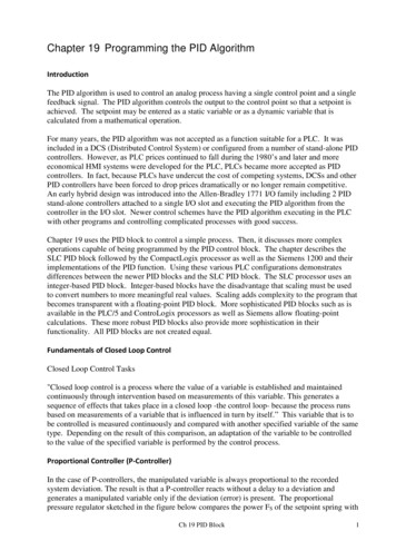
Processes in LabTwo processes in the lab are pictured on the following page in Fig. 19-18. The one on the left isthe water valve. The one on the right is the ball-in-tube. Fig. 19-17 shows the flow sensor forthe water valve. Information on the laser, the ball’s feedback sensor, is found in the instructionsfor the laser and the setup of the analog output in Fig. 19-19.The two processes are controlled by the two plc’s in the lab, A-B’s Compact Logix processor andthe Siemens S7-1200 processor. The feedback devices are both 4-20 mA input devices. Thevalve requires 4-20 mA from the CompactLogix processor to set the position while the fan motoris controlled by a pulsed 24 V output from the Siemens PLC.The following is a bill of material to construct the flow valve system shown below in Fig. 19-18.Fig. 19-18 Water Valve HardwareCh 19 PID BlockBall in Tube Hardware18
Fig. 19-19 The A-B PLC showncontrolling the Flow ValveFig. 19-20The Flow Sensor InputThe flow sensor is a paddle wheel placed in the flow of water. There is a calibrated readout forthe flow meter that displays the flow in gallons per minute.Ch 19 PID Block19
Fig. 19-21 Signet Flow Instrument as seen in LabCh 19 PID Block20
The laser is the feedback device for the ball-in-tube experiment. The laser gives an accurateposition of the top of the ball. Specifications for the laser are given in the following figure.Fig. 19-22 Instructions for Laser for Ball-in-Tube LabCh 19 PID Block21
Calibration of the analog output for the laser is described in the following figure. Thiscalibration may be ignored, however, due to the programming techniques used.Fig. 19-23The calibration can be ignored with the program as written. When the program initializes, theball is sent to the top of the tube and stays there for a short period of time. The laser output atthis value becomes the 100% value. When at rest at the bottom, this value is the 0% value.While the calibration may vary for different lasers installed, this process sets the limits of theprocess from which values for the high and low limits may be set. If this kind of self-calibrationis possible with your process, the calibration set-up becomes very easy.Ch 19 PID Block22
Siemens Analog Inputs and OutputsThe Siemens’ PID implementation follows a similar path to that of the SLC program. First, theaddress of all I/O is required as well as the wiring diagram for each analog point. The S7-1200has two analog inputs located on the controller. There is an analog output added by the signalboard but the decision was made to add analog outputs with a high resolution card attached to theright. This card is shown in the figure below:Fig. 19-24Addressing for the two analog input channels is found below: IW64 and IW66. The two analoginputs are wired to these two points and programmed with these addresses.Fig. 19-25Ch 19 PID Block23
To read or write an analog value, use the immediate read or write instruction as shown below:Use a cyclic interrupt event to house the PID function. The event is defined as an OB or ObjectBlock. We will use OB 30 for the program containing the PID Block for the Ball in Tube.Analog values are also available from high speed digital input pulses. Analog output values maybe realized through PTO or PWM signals from digital outputs. An example is the Tank overTank problem discussed in Chapter 25 of the Hybrid Lab Text. The configuration of the pulseinput is as follows:Ch 19 PID Block24
The configuration of the PWM output for control of the bilge pump is a single PWM 24 V outputthat turns on a power supply output:Ch 19 PID Block25
Ch 19 PID Block26
PID controlSTEP 7 provides the following PID instructions for the S7-1200 CPU:The PID Compact instruction is used to control technical proce
An early hybrid design was introduced into the Allen-Bradley 1771 I/O family including 2 PID stand-alone controllers attached to a single I/O slot and executing the PID algorithm from the controller in the I/O slot. Newer control schemes have the PID algorithm executing in the PLC