Transcription
An Introduction to ProportionalIntegral-Derivative (PID) ControllersStan ŻakSchool of Electrical and ComputerEngineeringECE 382Fall 20161
Motivation Growing gap between “real world” controlproblems and the theory for analysis anddesign of linear control systemsDesign techniques based on linear systemtheory have difficulties with accommodatingnonlinear effects and modeling uncertaintiesIncreasing complexity of industrial process aswell as household appliancesEffective control strategies are required toachieve high performance for uncertaindynamic systems2
Usefulness of PID ControlsMost useful when a mathematical model ofthe plant is not available Many different PID tuning rules available Our sources K. Ogata, Modern Control Engineering, FifthEdition, Prentice Hall, 2010, Chapter 8IEEE Control Systems Magazine, Feb. 2006,Special issue on PID control Proportional-integral-derivative (PID)control framework is a method to controluncertain systems3
Type A PID Control Transfer function of the type A PID controller U (s )1GPID (s ) K p 1 Td s E (s ) Ti s The three term control signal,1()()U s K p E s K i E (s ) K d sE (s )s In the time domain,Kptde(t )e(τ )dτ K pTdu (t ) K p e(t ) Ti 0dt4
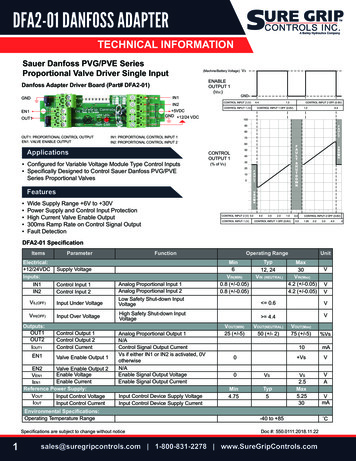
PID-Controlled SystemPID controller in forward path5
PID Tuning Controller tuning---the process of selecting thecontroller parameters to meet given performancespecificationsPID tuning rules---selecting controller parametervalues based on experimental step responses ofthe controlled plantThe first PID tuning rules proposed by Zieglerand Nichols in 1942The Ziegler-Nichols tuning rules provide astarting point for fine tuningOur exposition is based on K. Ogata, ModernControl Engineering, Prentice Hall, Fifth Edition,2010, Chapter 86
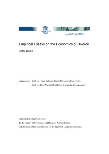
PID Tuning---First method (open-loopmethod)Start with obtaining the step response7
The S-shaped Step ResponseParameters of the S-shaped step response8
Transfer Function of System WithS-Shaped Step ResponseThe S-shaped curve may be characterizedby two parameters: lag (delay) time L, andtime constant T The transfer function of such a plant maybe approximated by a first-order systemwith a transport delay C (s ) Ke U (s ) Ts 1 Ls9
PID Tuning---First method (open-loopmethod)10
Transfer Function of PID ControllerTuned Using the First Method11
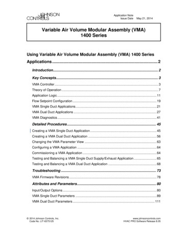
Ziegler-Nichols PID Tuning---Secondmethod (closed-loop method)Use the proportional controller to forcesustained oscillations12
PID Tuning---Second method (closed-loopmethod)Measure the period of sustained oscillation13
PID Tuning Rules---Second method (closed-loopmethod)14
Transfer Function of PID ControllerTuned Using the Second Method15
Example 1---PID Controller for DC MotorPlant---Armature-controlled DC motor;MOTOMATIC system produced by ElectroCraft Corporation Design a Type A PID controller andsimulate the behavior of the closed-loopsystem; plot the closed-loop system stepresponse Fine tune the controller parameters so thatthe max overshoot is 25% or less 16
Armature-Controlled DC Motor Modeling17
Physics---The Magnetic FieldOersted (1820): A current in a wire can producemagnetic effects; it can change the orientation ofa compass needle18
Force Acting on a Moving Charge in aMagnetic Field Force Magnitude F q0v BF q0vB sin θThe unit of B (flux density)---1Tesla, where1 Weber4 10 Gauss1 Tesla 21m19
Torque on a Current LoopThe force F4 has the same magnitude asbut points in the opposite directionF220
An End View of the Current LoopThe common magnitude ofF1andF3isiaB21
Building a Motor From a Current Loop22
DC Motor ConstructionTo keep the torque in the same directionas the loop rotates, change the directionof the current in the loop---do this usingslip rings at 0 and π (pi) or - π The brushes are fixed and the slip ringsare connected to the current loop withelectrical contact made by the loop’s sliprings sliding against the brushes 23
Modeling Equations Kirchhoff’s Voltage Law to the armature circuitU (s) ( La s Ra ) I a ( s ) Eb ( s ) Back-emf (equivalent to an ”electrical friction”) Torque developed by the motorEb (s ) K bΩ m (s )Tm ( s ) (Js Bm s ) Θ m ( s )2mElectromechanical couplingTm (s ) K t I a (s )24
Relationship between K t and Kb Mechanical power developed in the motorarmature (in watts)p eb (t )ia (t ) Mechanical power can also be expressed asp Tm (t )ωm (t ) CombineTmp Tm ωm ebia K b ωmKt25
In SI Units K t K b The back-emf and the motor torque constants areequal in the SI unit system V Kt K b (N m / A ) rad / sec 26
Transfer Function of the DC MotorSystem Transfer function of the DC motorY (s)0.1464G p (s)U ( s ) 7.89 10 7 s 3 8.25 10 4 s 2 0.00172 swhere Y(s) is the angular displacement of themotor shaft and U(s) is the armature voltage27
Tuning the Controller Using the SecondMethod of Ziegler and Nichols Use the Routh-Hurwitz stability test;see page 212 of the Text DetermineK cr DeterminePcr Compute the controller parameters28
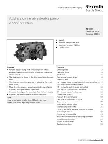
Generating the Step Responset 0:0.00005:.017;K cr 12.28; P cr 135;K 0.075*K cr*P cr; a 4/P cr;num1 K*[1 2*a a 2]; den1 [0 1 0];tf1 tf(num1,den1);num2 [0 0 0 0.1464];den2 [7.89e-007 8.25e-004 0.00172 0];tf2 tf(num2,den2);tf3 tf1*tf2;sys feedback(tf3,1);y step(sys,t); m max(y);29
Closed-Loop System Performance30
Example 2 (Based on Ex. 10-3 in Ogata, 2002) Use a computational approach togenerate an optimal set of the DC motorPID controller’s parameters(s a)G (s ) K2c sGenerate the step response of the closedloop system31
Optimizing PID Parameterst 0:0.0002:0.02;font 14;for K 5:-0.2:2%Outer loop to vary the values of%the gain Kfor a 1:-0.01:0.01;%Outer loop to vary the%values of the parameter anum1 K*[1 2*a a 2]; den1 [0 1 0];tf1 tf(num1,den1);num2 [0 0 0 0.1464];den2 [7.89e-007 8.25e-004 0.00172 0];tf2 tf(num2,den2);tf3 tf1*tf2;sys feedback(tf3,1);y step(sys,t); m max(y);32
Finishing the Optimizing Programif m 1.1 & m 1.05;plot(t,y);grid;set(gca,'Fontsize',font)sol [K;a;m]break % Breaks the inner loopendendif m 1.1 & m 1.05;break; %Breaks the outer loopendend33
Closed-Loop System Performance34
Modified PID Control SchemesIf the reference input is a step, thenbecause of the presence of the derivativeterm, the controller output will involve animpulse function The derivative term also amplifies higherfrequency sensor noise Replace the pure derivative term with aderivative filter---PIDF controller Set-Point Kick---for step reference thePIDF output will involve a sharp pulsefunction rather than an impulse function 35
The Derivative TermDerivative action is useful for providing aphase lead, to offset phase lag caused byintegration term Differentiation increases the highfrequency gain Pure differentiator is not proper or causal 80% of PID controllers in use have thederivative part switched off Proper use of the derivative action canincrease stability and help maximize theintegral gain for better performance 36
Remedies for Derivative Action---PIDFController Pure differentiator approximationTd sγ Td s 1γwhereis a small parameter, forexample, 0.1 Pure differentiator cascaded with a firstorder low-pass filter37
The Set-Point Kick PhenomenonIf the reference input is a step function,the derivative term will produce animpulse (delta) function in the controlleraction Possible remedy---operate the derivativeaction only in the feedback path; thusdifferentiation occurs only on the feedbacksignal and not on the reference signal 38
Eliminating the Set-Point KickPID controller revisited39
Eliminating the Set-Point Kick---Finding thesource of troubleMore detailed view of the PID controller40
Eliminating the Set-Point Kick---PI-DControl or Type B PIDOperate derivative action only in thefeedback41
I-PD---Moving Proportional andDerivative Action to the FeedbackI-PD control or Type C PID42
I-PD Equivalent to PID With InputFilter (No Noise)Closed-loop transfer function Y(s)/R(s) of the IPD-controlled systemY (s) R (s)KpTi sGp ( s ) 1 Td s G p ( s )1 K p 1 Ti s 43
PID-Controlled System Closed-loop transfer function Y(s)/R(s) of the PIDcontrolled system with input filter 1K p 1 Td s G p ( s )Ti sY (s)1 2R ( s ) 1 Ti s TT 1i ds1 K p 1 Td s G p ( s ) Ti s After manipulations it is the same as the transferfunction of the I-PD-controlled closed-loop system44
PID, PI-D and I-PD Closed-LoopTransfer Function---No Ref or NoiseIn the absence of the reference input andnoise signals, the closed-loop transferfunction between the disturbance input andthe system output is the same for the threetypes of PID controlY (s ) D (s )G p (s ) 1 Td s 1 K p G p (s ) 1 Ti s 45
The Three Terms of ProportionalIntegral-Derivative (PID) Control Proportional term responds immediately to thecurrent tracking error; it cannot achieve thedesired setpoint accuracy without anunacceptably large gain. Needs the other termsDerivative action reduces transient errorsIntegral term yields zero steady-state error intracking a constant setpoint. It also rejectsconstant disturbances Proportional-Integral-Derivative (PID)control provides an efficient solution tomany real-world control problems46
SummaryPID control---most widely used controlstrategy today Over 90% of control loops employ PIDcontrol, often the derivative gain set tozero (PI control) The three terms are intuitive---a nonspecialist can grasp the essentials of thePID controller’s action. It does not requirethe operator to be familiar with advancedmath to use PID controllers Engineers prefer PID controls overuntested solutions 47
Modern Control Engineering, Fifth Edition, Prentice Hall, 2010, Chapter 8 . specialist can grasp the essentials of the PID controller's action. It does not require . Engineers prefer PID controls over untested solutions . Title: PID Control---ECE 680 Author: S. H. Zak Created Date: 12/5/2016 2:20:21 PM .