Transcription
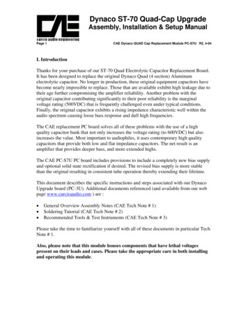
Dynaco ST-70 Quad-Cap UpgradeAssembly, Installation & Setup ManualPage 1CAE Dynaco QUAD Cap Replacement Module PC-S7U R2, 4-04I. IntroductionThanks for your purchase of our ST-70 Quad Electrolytic Capacitor Replacement Board.It has been designed to replace the original Dynaco Quad (4 section) Aluminumelectrolytic capacitor. No longer in production, these original equipment capacitors havebecome nearly impossible to replace. Those that are available exhibit high leakage due totheir age further compromising the amplifier reliability. Another problem with theoriginal capacitor contributing significantly to their poor reliability is the marginalvoltage rating (500VDC) that is frequently challenged even under typical conditions.Finally, the original capacitor exhibits a rising impedance characteristic well within theaudio spectrum causing loose bass response and dull high frequencies.The CAE replacement PC board solves all of these problems with the use of a highquality capacitor bank that not only increases the voltage rating (to 600VDC) but alsoincreases the value. Most important to audiophiles, it uses contemporary high qualitycapacitors that provide both low and flat impedance capacitors. The net result is anamplifier that provides deeper bass, and more extended highs.The CAE PC-S7U PC board includes provisions to include a completely new bias supplyand optional solid state rectification if desired. The revised bias supply is more stablethan the original resulting in consistent tube operation thereby extending their lifetime.This document describes the specific instructions and steps associated with our DynacoUpgrade board (PC-3U). Additional documents referenced (and available from our webpage www.curcioaudio.com ) are : General Overview Assembly Notes (CAE Tech Note # 1)Soldering Tutorial (CAE Tech Note # 2)Recommended Tools & Test Instruments (CAE Tech Note # 3)Please take the time to familiarize yourself with all of these documents in particular TechNote # 1.Also, please note that this module houses components that have lethal voltagespresent on their leads and cases. Please take the appropriate care in both installingand operating this module.
Dynaco ST-70 Quad-Cap UpgradeAssembly, Installation & Setup ManualPage 2CAE Dynaco QUAD Cap Replacement Module PC-S7U R2, 4-04II. General OverviewTake time to review all of the documentation provided including the aforementioned technotes related to soldering technique and proper tools and test equipment. In the followingsections we will guide you through several project phases. Each section has beencarefully prepared with our own notes and comments from our customers to be sure thatany anticipated question has been considered. The sequence is identical to that which wefollow when we complete the fabrication for our customers. Please follow the samesequence to maximize efficiency and eliminate errors. It is also very helpful to read eachsection before beginning to gain a visual idea of the construction.Your project will be built in stages: If you have purchased the PC Board in its unassembled form (PWB-S7U) you willfirst assemble the components onto that board. Next, you will the remove original Dynaco Aluminum QUAD AluminumElectrolytic “Can” and the original “selenium” rectifier (the bias supply rectifier) andcarefully label each of the associated wires. You will then install the CAE replacement PC-S7U Board and reconnect the originalwires to their corresponding terminals followed by a few electrical tests and power upsequence. Finally you will readjust the bias pots for each channel.Although you are unlikely to encounter any problems, should they occur they wouldalmost certainly be based on an improper assembly of the PC Board or the wiring to theStereo 70. Therefore to avoid the time consuming and frustrating task of troubleshootingafterwards please remember these simple suggestions: Proper soldering is crucial. Please refer to our soldering tutorial and practice onsurplus boards until you master the technique. Be especially careful to avoid solderbridges or “cold” solder joints. Our experience shows that nearly 95% of all problemsare associated with soldering related errors. Diodes & Capacitors (the project is full of them) are polar- this means that there is aright and wrong way to insert polarized components in the board. If placedbackwards, the component and probably others nearby will be damaged upon initialpower application. Double check each step associated with these parts and once againlater after you have had a chance to take a break. Some components are color coded with their value (mostly resistors, but there maybe others). If you are not proficient at reading these codes, use an ohmmeter to doublecheck the value of each resistor before insertion. It is very easy to confuse a 100 ohmmetal film resistor with a 1000 ohm resistor or worse with a 100K ohm resistor.
Dynaco ST-70 Quad-Cap UpgradeAssembly, Installation & Setup ManualPage 3CAE Dynaco QUAD Cap Replacement Module PC-S7U R2, 4-04III. Internal WiringUnless otherwise specified, you should use 20 to 22 gauge stranded wire with Tefloninsulation. Thicker wire, solid wire, or PVC insulation will cause problems - if not now(too much strain on the boards or parts) or later (reliability issues). We can’toveremphasize this issue.III. AssemblyA. Building the PC Board (PC-S7U)Components are to be inserted on the non foil side and soldered on the foil side. Thesequence of assembly has been chosen so that the components with the lowest profile(such as jumpers, low power resistors, IC’s etc.) are installed first with higher profilecomponents added until the highest profile components are installed last.Refer to the component placement drawing (figure 1). Be sure to observe correctorientation of polar components (capacitors). Be sure also to check with an ohmmeterresistor values if you are not absolutely sure of how to read metal film resistor colorcodes.1. Begin by installing all of the ½ Wattresistors. There are a total of 10 ½ Wattresistors (14 if you are installing the solidstate rectifier option). Refer to Figure 1(Top View PC Board ComponentPlacement Diagram). The board has beendesigned so that a gentle radius near thebody of the resistor will position the leadsin alignment with the associated holes inthe PC Board.Note that the ½ Watt resistors should beinserted so that the body of the resistorrests gently against the PC Board. Afterinserting the resistor leads thru the board, aslight bending outward of the leads willhold the part in place until you can solder itin place.2. Install the single 1N4007 diode (D5) for the bias supply. It is located furthest from thecapacitor grouping and points (band side) towards the edge of the board. If you will beusing the solid state rectifier option, install the four 1N4007 diodes (D1 thru D4). Thesepoint in the opposite direction from D5.
Dynaco ST-70 Quad-Cap UpgradeAssembly, Installation & Setup ManualPage 4CAE Dynaco QUAD Cap Replacement Module PC-S7U R2, 4-043. Install the Two (2) 3 Watt metal Oxide resistors. You should also gently bend the leadsof these resistors similar to the ½ Watt resistors (but of course with a greater radius). Butunlike the ½ Watt resistors, the # Watt Resistors should be spaced away from the plane ofthe PC Board by 1/16” to allow for heat dissipation.4. Install the eight (8) electrolytic capacitors (4X 100@250VDC & 4X100uF@350VDC). Be very careful to observe the correct polarity and voltage rating. The350VDC 100uF caps are 7/8” diameter. The black band on the capacitor represents thenegative lead (the board is market with a “ ” to indicate the positive (opposite) lead. Becareful to insure that the leads fully extend thru the PC Board and that you have sufficienttab length to obtain a solid solder connection.5. Finally install the two remaining electrolytic capacitors (2X 47uF @ 10VDC – theseare about ½” in diameter) for the bias supply. Note the polarity as shown in Figure 1.6. Visually inspect all of your solderconnections. Refer to the adjacent diagram.Quality solder connections should besmooth and shiny. Dull surface or largeblobs on the PC board should be cleanedand resoldered. In this case remove the oldsolder with solder wick or similar andresolder the connection.B. Removing the Original Dynaco QUAD Capacitor & Bias Rectifier1. To begin removing the original Dynaco Quad Capacitor, remove the top cover(should be held in place with either 4 or six screws (depending upon the vintage)along the side. These screws will release both the top perforated metal cage andthe bottom “U” cover.2. Remove the 4 output tubes, the rectifier tube, and the two 7199 driver tubes (andlabel them for reinstallation later). I recommend that you clean the dust andgrime from the amplifier both topside and below where you will be doing most ofyour work. A vacuum cleaner following the path of a soft paintbrush will workvery well here.3. Turn the amplifier over and locate the wire connected to Quad capacitor section“A”. The other end should be connected to the Dynaco driver PC board (PC-3)terminal number “19”. Desolder the wire at the PC board (you can leave the otherend connected to the Quad Capacitor. Note - There is also a 22K resistorconnected to capacitor lug “A” – we will discard it so feel free to leave itconnected.
Dynaco ST-70 Quad-Cap UpgradeAssembly, Installation & Setup ManualPage 5CAE Dynaco QUAD Cap Replacement Module PC-S7U R2, 4-044. Next locate the wire connected to Quad capacitor section “B”. The other endshould be connected to the Dynaco driver PC board (PC-3) terminal number “20”.Desolder the wire at the PC board (you can leave the other end connected to theQuad Capacitor. Note – There are two resistors connected to lug “B” – ignorethem as they will be discarded.5. Next, desolder the wires connected to capacitor section “B”. There are 3: thechoke lead, and one RED lead from each of the output transformers. There is alsothe other side of the 6.8K resistor referenced in the last step – it can remain.Label each of these wires “C”.6. Next, at Quad capacitor lug “D”, there are two wires: the other lead from thechoke and a wire going to pin 8 of the rectifier tube. Desolder the wire going topin 8 of the rectifier tube at the rectifier tube. Desolder the choke lead and label it“D”. For your reference, you can identify pin 8 by counting clockwise from thebottom of the tube starting at the tab.7. Next, remove the two wires connected to the posts of the selenium rectifier(located near the center of the amplifier). There are two: a wire leading to thepower transformer – label this wire “RED-BLK”. The other wire leading to theterminal strip under the right channel output transformer will not be used – cut itat both ends and discard. You can now remove the selenium rectifier and itsassociated hardware (1/4” nut & 1.25” screw).8. All the connections to the original electrolytic “can” capacitor should be removedat this time. This capacitor is held in place by 4 tabs that are either twisted and / orsoldered to the chassis. You will need to remove the solder (using a vacuum“solder sucker”) to easily remove it. This is perhaps the most difficult step of theprocess. Make sure your soldering iron tip is clean and “wetted” with a fresh shotof solder and immediately begin to heat the connection. Wait until the solder isfully molten (this may take a minute or so) and then place the solder vacuumpump in a position to suck the greatest quantity of solder. Once you have removedthe solder, using gas pliers you can twist the tabs to the position (faceperpendicular to the center of the can) that will release the capacitor.9. Remove the ground lug that is located between the right channel bias pot & theoriginal Quad capacitor. Do not desolder the wires to this lug – it will bereattached soon.10. The bias potentiometers are located near the center of the amplifier flanking theoriginal selenium rectifier. On one of the potentiometers (most likely the leftchannel) on the two outer terminals (not the center terminal) there are long wiresthat route to a terminal strip located below the left channel power transformer.
Dynaco ST-70 Quad-Cap UpgradeAssembly, Installation & Setup ManualPage 6CAE Dynaco QUAD Cap Replacement Module PC-S7U R2, 4-04There should be two wires; one for each outer terminal. Remove both of thesewires completely and discard (cut both of these wires at both ends). Be careful tokeep intact the connections at the bias pot terminals that connect both of the potsouter terminals together – these must remain.11. At your discretion you may remove all of the original bias components hardwiredon the terminal strip below the left output transformer. This includes everythingbut the three terminal ceramic disc capacitor.C . Installation of the New CAE Stereo 70 QUAD Capacitor Board (CAE-PC-S7U)1. Locate the CAE replacement Driver board (PC-S7U). There are 8 wires (or 10 ifyou are using the solid state rectifier option) wires that need to be connected tothis board that interface with the amplifier. They are: “BIAS – “ - one wire connecting to the set of bias potentiometers “BIAS “ - one wire connecting to the set of bias potentiometers “RD-BLK” - one wire connecting to the Power Transformer Red-Black Stripelead “A” - one wire connecting to terminal 19 of the Dynaco PC-3 board “B” - one wire connecting to terminal 20 of the Dynaco PC-3 board “C” - one wires that will connect to the choke and the 2 output transformers “D” - one wire connecting to the rectifier tube pin 8 “GND” - one wire connecting to the chassis “RD” - one wire each connecting to one of the RED power transformer leads ifsolid state rectification options is used & “RD” - one wire each connecting to the other RED power transformer leads ifsolid state rectification options is used2. Most of the original wires will be too short to reach the terminals of thereplacement capacitor board once in place. I suggest preparing a set of 8 (10 ifyou are using the solid state rectifier option) wires to connect from the PC-S7Ureplacement cap board to the associated connections inside the amplifier. To dothis, cut 11 (or 12) 12” lengths of 22 ga. stranded wire (preferably Tefloninsulated) and strip 3/8” of insulation from one end of each wire. Tin the wire andconnect one wire each to the PC-S7U terminals “RD-BLK”, “BIAS-“, “BIAS ”,“A”, “B”, “D”, & “C”. If you are using the solid state rectifier option connect onewire each to terminal “RD” and another to the other terminal “RD”. Label eachwire according to the terminal nomenclature.3. Group the wires and insert the bundle from the top of the amplifier through to thebottom through the hole originally occupied by the Dynaco Quad capacitor.Orient the PC-S7U so that the diode area is nearest the right output transformer
Dynaco ST-70 Quad-Cap UpgradeAssembly, Installation & Setup ManualPage 7CAE Dynaco QUAD Cap Replacement Module PC-S7U R2, 4-04and insert the two threaded standoffs into the holes previously occupied by theselenium rectifier and the ground lug. The two large holes in the PC-S7U boardshould align with the two bias potentiometers so that you can access them with along flat screwdriver. Secure the PC-S7U in places with two 4-40 nuts. Be sure tocapture the ground lug with one of the nuts.
Dynaco ST-70 Quad-Cap UpgradeAssembly, Installation & Setup ManualPage 8CAE Dynaco QUAD Cap Replacement Module PC-S7U R2, 4-04You will now connect the PC-S7U to the amplifier in the following steps:1. Locate the wire from the PC-S7U board labeled “A”. Trim to length and strip ¼”insulation from the end. Connect to terminal 19 on the Dynaco PC-3 driver board.2. Locate the wire from the PC-S7U board labeled “B”. Trim to length and strip ¼”insulation from the end. Connect to terminal 20 on the Dynaco PC-3 driver board.3. Locate the wire from the PC-S7U board labeled “BIAS ” (Bias POSITIVE).Trim to length and strip 3/8” insulation from the end. Connect this wire to therightmost terminal of the bias right channel bias potentiometer (the one nearestthe Quad Cap cutout).4. Locate the wire from the PC-S7U board labeled “BIAS-” (Bias NEGATIVE).Trim to length and strip 3/8” insulation from the end. Connect this wire to theleftmost terminal of the bias right channel bias potentiometer (the one nearest theQuad Cap cutout).5. Locate the wire from the PC-S7U board labeled “GND”. Trim to length and strip3/8” insulation from the end. Connect this wire to the ground lug near the QuadCap cutout.6. Locate the wire from the PC-S7U board labeled “D”. Trim to length and strip 3/8”insulation from the end. Connect this wire to pin 8 of the rectifier tube. You canidentify pin 8 by counting clockwise from the bottom of the tube starting at thetab.7. Connect one end of the choke also to pin 8 of the rectifier tube. It will probably benecessary to increase the length of this wire. To do so splice, solder, and cover thesplice with electrical tape or heat shrink tubing.8. Locate the wire from the PC-S7U board labeled “RD-BL”. Trim to length andstrip 3/8” insulation from the end. Splice this wire to the power transformer leadlabeled “RED-BLK”. Solder to secure and finish with either electrical tape orheat shrink tubing.9. The next step will involve splicing together 4 wires: the two output transformerred leads, the remaining choke lead, and PC-S7U wire labeled “C”. Clean the oldsolder from the two transformers leads and the choke lead. Cut to length the wirelabeled “C” and strip 3/8” insulation from the end. Twist all four together andsecure with a quality solder connection. Cover the end with electrical tape or heatshrink tubing.
Dynaco ST-70 Quad-Cap UpgradeAssembly, Installation & Setup ManualPage 9CAE Dynaco QUAD Cap Replacement Module PC-S7U R2, 4-0410. If you will be using the solid state rectifier option perform the following twosteps: Locate one of the wires from PC-S7U labeled “RD”. Trim to length,remove 3/8” insulation, and connect to pin 6 of the rectifier tube Locate the other wire from PC-S7U labeled “RD”. Trim to length, remove3/8” insulation, and connect to pin 4 of the rectifier tube.Once completed, inspect each connection again and carefully look for signs of meltedinsulation near adjacent wires.D . Final Checkout & Initial Power Application1. Replace the power fuse (3A Slo-Blo) with a 1A AGC (quick trip). Install the twodriver tubes (7199).2. If you are not using the solid state rectifier option, plug in the rectifier tube.Please note, it you are using the solid state rectifier option do not install therectifier tube. Connect a voltmeter to pin 8 of the rectifier tube. The negative lead(Black) should be connected to the amplifier chassis. The positive lead (Red)should be connected to pin 8 of the rectifier tube. Set the voltmeter to measure500 Volts DC.3. Plug in and apply power to the amplifier. The voltage reading should beapproximately 475 to 550 VDC. If you are suing a tube rectifier, this readingshould appear after approximately 30 seconds – if you are using the solid stateoption, it should appear immediately.4. Measure the voltages at the outer terminals of one of the bias potentiometers. Atone terminal (the – BIAS) you should measure approximately – 39 VDC. At theother terminal (the BIAS) you should measure approximately – 26 VDC. Areading within 10% is acceptable. If you do not measure these values do notproceed – check out the bias capacitors and the wiring associated with powertransformer lead “RED-BLK”. Power down and wait 15 minutes.5. Place RCA shorting plugs into both left and right signal inputs of your Stereo 70.Install the two left channel output tubes. Do not install the right channel outputtubes right now. Replace the original 3A fuse. Rotate both original BiasPotentiometers fully counterclockwise. Connect your DC Voltmeter to monitorthe current thru the output tubes by measuring the voltage across the 15.6 ohmresistor located at pins 1 & 8 of the output tubes - connect the negative lead(Black) to the chassis and connect the Positive lead (Red) to the junction of the
Dynaco ST-70 Quad-Cap UpgradeAssembly, Installation & Setup ManualPage 10CAE Dynaco QUAD Cap Replacement Module PC-S7U R2, 4-0415.6 ohm resistor and the Output Tube pins 1 & 8. Monitor the voltage as thetubes reach operating temperature. If the voltage begins to exceed 2.5 voltsquickly remove power. Otherwise adjust the Bias pot to obtain 15.6 volts.Remove power.6. Install the right channel output tubes, apply power, and repeat the procedureoutlined in step 3. Recheck the bias on the left channel. Remove power.7. Replace the cover and enjoy.
Dynaco ST-70 Quad-Cap UpgradeAssembly, Installation & Setup ManualPage 11CAE Dynaco QUAD Cap Replacement Module PC-S7U R2, 4-04
Dynaco ST-70 Quad-Cap UpgradeAssembly, Installation & Setup ManualPage 12CAE Dynaco QUAD Cap Replacement Module PC-S7U R2, 4-04
Dynaco ST-70 Quad-Cap UpgradeAssembly, Installation & Setup ManualPage 13CAE Dynaco QUAD Cap Replacement Module PC-S7U R2, 4-04CAE QUAD Cap & Bias ModuleStereo 70 QUAD Capacitor & Bias Supply Module, CAE# ASM-S7UDESIGDESCRIPTIONQNTYC1, C3, C5, C7CAPACITOR, ELECTROLYTIC (RADIAL)4C2, C4, C6, C8C9,C10D1 To D5(OPT)R1,R2,R3,R4R5, R7, R9, R11R6, R8, R10,R12R13R14R15, R16X1X3CAPACITOR, ELECTROLYTIC (RADIAL)CAPACITOR, ELECTROLYTIC (RADIAL)NOTES:CAE# - Curcio Audio Part NumberDK# - DigiKey Part NumberMSR# - Mouser Part Number6-04R2PAGE 142PART 0-XRL-100V47VAL / VOLT100uF/350VDC47uF/100VDCDIODE, POWER, HIGH SPEEDRESISTOR, CARBON FILMRESISTOR, CARBON FILM544MSR#583-1N4948MSR#293-470KMSR#293-220K1000 V / 1A470K, 1/2W220K, 1/2 WRESISTOR, CARBON FILMRESISTOR, METAL OXIDERESISTOR, METAL OXIDERESISTOR, METAL OXIDEPRINTED CIRCUIT BOARDPC BOARD STANDOFFS, SR#283-10KCAE# PC-S7UCAE# 512-5011390K, 1/2 W6.8K, 3W22K, 3W10K, 3W100uF/250VDC
Dynaco ST-70 Quad-Cap UpgradeAssembly, Installation & Setup ManualPage 14CAE Dynaco QUAD Cap Replacement Module PC-S7U R2, 4-04
Dynaco ST-70 Quad-Cap UpgradeAssembly, Installation & Setup ManualPage 15CAE Dynaco QUAD Cap Replacement Module PC-S7U R2, 4-04
Dynaco ST-70 Quad-Cap Upgrade Assembly, Installation & Setup Manual Page 2 CAE Dynaco QUAD Cap Replacement Module PC-S7U R2, 4-04 II. General Overview Take time to review all of the documentation provided including the aforementioned tech notes related to soldering technique and proper tools and test equipment. In the following

