Transcription
./720(07)157AH Fecferal Housing AdSnfetrdtinwv.8pt.lmm**#**'’International Correspondence Schools, Scranton, Pa.rArchitectural DrawingPrepared especially for home studyByrWILLIAM S. LOWNDES, Ph. B., A.I.A.andFREDERICK FLETCHER, A.I.A.Registered Architect5637 A-3Part 1Edition 36 AssignmentsInternational Correspondence Schools, Scranton, PennsylvaniaInternational Correspondence Schools, Canadian, Ltd., Montreal, Canada
(O Si u U(jARCHITECTURAL DRAWING\/.VPart 1“The higher men climb, the longertheir working day. And to keep at thetop is harder, almost, than to get there.There are no 4office hours' for leaders."—Cardinal Gibbons%*WILLIAM S. LOWNDES, Ph.B., A.I.A.andBut for the man who has found the job he loves, work isno longer “labor.” And learning more about that job be*comes a thrilling, exciting adventure.FREDERICK FLETCHER, A.I.A.Registered Architect23t:Serial 5637A-3Copyright 1962, 1954, 1951, 1943, byINTERNATIONAL TEXTBOOK COMPANYCopyright in Great Britain. All rights reserved.Printed in United States of America: .International Correspondence SchoolsjScranton, Pennsylvania /r1International Correspondence Schools Canadian, Ltd{Montreal, Canada
121o1(5VvARCHITECTURAL DRAWINGlPART 1PIINTRODUCTIONWhat This Text Covers . . .1. Introduction to Architectural Drawing . Pages 1 to 12Architectural drawing is the special language of the architect.Various kinds of architectural drawings are explained. The use ofpaper is described. Each paper has its particular use.2. Symbols and IndicationsPages 13 to 21Symbolism is used in architectural drawing. In this section, youwill find symbols for materials, architectural features, plumbingfixtures, and electrical outlets.3. Details of WindowsPages 22 to 40The construction of many types of windows is explained. Screensand shutters are included.4. Doors and CornicesPages 41 to 57Details for exterior doors in frame and masonry walls are shownand explained. Details of interior doors are given. Cornicesare illustrated.5. Interior DetailsPages 38 to 71You will be interested in the many interior details that are shownin this section. The detailing of a chimney requires considerablecare. Stairs, doors, interior trim, and wainscot are included.6. Key to Criticism5637APage 721. Definition of Architectural Drawing.—Architecturaldrawing is the special language of the architect, which he usesto convey to his client impressions of how a contemplated build ing will appear when completed. It is also used to convey to thecontractors and workmen who perform the work of erectionthe information regarding size, form, materials, dimensions,etc. necessary to enable them to estimate the probable cost ofthe building, and to erect the building as the architect con ceives it in his own mind.Architectural drawing is based on the principles of projectiondrawing, which are applied in making the working drawingsrequired for the erection of the building. It also employs theprinciples of perspective in drawings that show the building as itwill actually appear when viewed from some particular point.2. Architectural drawing does not require the extremeaccuracy that is called for in some forms of mechanical drawing.A sufficient degree of accuracy is obtained by placing lines ofdimensions on the drawings to define the limits of certain por tions of a building. Where precision is required, large-sizedrawings are made which show details at exact size.Freehand drawing is employed to a great extent in architec tural drawing. In designing a building the architect generallyfinds it helpful and often absolutely necessary to make numerousfreehand studies or sketches illustrating various portions of thedesign. In making these studies a thorough knowledge of free hand drawing and facility in handling a pen or pencil are essen tial. Familiarity with the principles of perspective drawing willalso be found invaluable. These freehand studies, the architect'sfirst conception of a problem, are generally made with a soft" **7RiaHTEO BY INTERNATIONAL TEXTBOOK COMPANY.ALL lOHTS RK6BRVEO
ARCHITECTURAL DRAWING, PART 1ARCHITECTURAL DRAWING, PART 1pencil and without the use of instruments. In laying out aworking drawing, instruments such as are used in mechanicaland geometrical drawing are employed, and harder pencils areused than those used in making the studies.The elements of beaut}' and character should always be con sidered in making an architectural drawing. These elements arenot often considered in mechanical drawing, where the prin cipal aims are accuracy and economy in the use of materials.Although utilitarian considerations also enter into architecturaldrawing, they must be studied in conjunction with the expres sion of beauty and character.4. Technique of Architectural Drawing.—Methods usedin the production of drawings are described in previous texts,which also include instructions regarding the use of drawingboards, T-squares, triangles, drawing instruments, papers, pen cils, pens, etc., and require the making of a series of elementarydrawings.3. Importance of Architectural Drawing.—As has beenstated, architectural drawing is the special language of thearchitect. Without its use no building of any importance couldbe erected. The subject should be understood by all those inter ested in the construction of buildings, and in the education ofan architect a thorough knowledge of its meaning is funda mental.A person who is desirious of becoming an architect is urgedto study this most important subject thoroughly. He shouldpractice drawing whenever he has time to do so. A studentof this course should draw carefully and studiously all theplates and exercises called for in the texts on ArchitecturalDrawing and send them to the Schools for correction. Heshould also, as a means of self-improvement, study and copyas many as possible of the other drawings that are shown inthe illustrations throughout these texts, but these drawings arenot to be sent to the Schools for correction.By doing this work the student may feel assured that he isimproving himself in a way that will be of the greatest advan tage to him when the time comes for him to do practical archi tectural work. The beginner should always endeavor to havehis work neat and clean with clear, sharp lines and carefullettering, as neatness is very desirable. He should not, however,forget that his object is not only to draw lines neatly andaccurately, but to make them convey useful ideas. Otherwise thedrawing is of little practical value.i35. Nature of Architectural Drawing.—Architectural draw ing, in its complete sense, does not consist merely in makingmarks, lines, letters, and numerals on sheets of paper. It isthe language used to express ideas of the design of buildingsand their numerous parts, and to show the construction of thebuildings and the application of the materials of which the build ings are to be made.The numerous uses of architectural drawing as applied todesign, construction, and the uses of materials cannot be taughtin a single lesson. The subject is presented gradually, onlyenough design and construction being considered at one timeto explain the drawing that is being made.ARCHITECTURAL DRAWINGSDESCRIPTION OF CLASSESi6. Classification.—It is customary, in the course of pre senting a complete conception of a proposed building, to makeseveral kinds of drawings. These include preliminary studies,preliminary sketches, working drawings, scale details, and fullsize details.The preliminary studies are the freehand sketches which thearchitect or draftsman makes when formulating his ideas fora building. The preliminary sketches are those made to showto the client so that he may get a good general idea of the pro posed building and may make any changes that he desires be fore the permanent and detailed drawings are made. Boththe studies and the sketches will be described in a succeedingtext.
4ARCHITECTURAL DRAWING, PART 17. Working Drawings.—The working drawings must beas complete and accurate as possible; they are not merely pic tures. Every line, dot, mark, letter, and numeral must have adefinite meaning so that exact estimates of the cost of thework can be made and so that the building can be properlyerected from the drawings. Working drawings consist of sheetsshowing plans of the different floors, the basement, and theattic; elevations of the front, rear, and sides of the building;sections, through the principal portions of the structure. Thesections show details of particular parts that cannot be shownproperly on the plans or elevations. All necessary dimensionsshould be noted on these drawings. The working drawingsare generally drawn to the scale of \ inch to the foot. On verylarge work they are sometimes drawn to the scale of 4 inch tothe foot, so that the drawings may be made on sheets of paperor cloth of a convenient size.Working drawings are never rendered or colored, but areplain line drawings made with pencil or pen on tracing paperor cloth and then blueprinted. Colored washes and lines willnot reproduce in color on blueprints and are little used.The working drawings are first laid out accurately anddrawn in pencil on tracing paper, the materials of which thebuilding is to be constructed being indicated by various mark ings. After the dimensions have been carefully checked, thedrawings are traced on tracing paper or cloth, the tracing gen erally being done with pencil or India ink. When the dimensionsand notes are all carefully put in and the titles are lettered, thesheets are ready for blueprinting.The working drawings, together with the specifications, formthe basis of the contract to construct the building. Since theyare documents that form part of the contract, they are there fore sometimes referred to as contract drawings.8. Examples of Working Drawings.—In connection withthis text, working drawings are given which fully illustratethis form of architectural drawing. Other illustrative materialof this kind is found in the working drawings in this text aswell as in that of the succeeding text.ARCHITECTURAL DRAWING, PART 1.59. Scale Details.—After the working drawings have beencompleted and the specifications which describe the work to bedone on the building have been written, the architect proceedsto make scale details, which are drawings of certain parts ofthe building at a larger scale than that used for the workingdrawings. This is done with parts of the building, such as thewindows, doors, cornices, porch finishes, etc., which cannotbe shown clearly at a scale of J inch. The scales commonlyused in making these drawings are J, 1, l- , and 3 inches.10. Full-Size Details.—It is necessary to show some por tions of the building at full size. Carvings, moldings, and similardetails of a building cannot be satisfactorily shown in any otherway. Full-size details often make very large drawings, but cangenerally be shown on large sheets of heavy tracing or bondpaper from which prints can be made.11. Plans.—The plan of any object is the view of it asseen from above. In the case of buildings, there may be severalplans. These are horizontal sections, or cuts taken through thebuilding, one at each story, showing the building as it mightappear with the upper parts removed. The arrangement ofwalls, partitions, doors, windows, chimneys, stairs, etc., shouldall be shown in their proper relative positions and sizes.12. Elevations.—Elevations are projections or views ofthe exterior of a building or parts of a building, showing therelative heights and sizes of its various parts. The heights ofthe stories, windows, doors, porches, roofs, and chimneys areall shown. The term elevation is also applied to the projectionof any part of the building viewed horizontally.13. Sections.—Sections are cuts through the buildingmade by vertical planes. These drawings show the elevationsof the interiors of the various rooms, of the chimneys, and ofstairs, together with cuts or sections through the floors, walls,and roofs. A section is a very useful drawing, as it givesinformation that cannot be shown in an elevation or a plan.14. Use of Projection Drawing.—The principles of pro jection drawing are employed in making plans, elevations, and
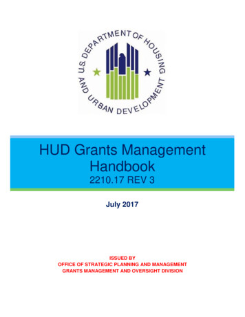
architectural drawing, part61ARCHITECTURAL DRAWING, PART 17ffTTiMimfr k-fflIffllr.-*C' fcftVmas -DDOQffOk9i-lfil #aiag DD 7tAX xir' X: - xEl „-.C.-xr —' Frojst itl-fflii 5ps, 5ID& &L \ ATlO.N (a)El atiON '(a)P[B ATHBSD ROOM.lZ-0"x 9-6"""CLO. I CLO. I L.4 DI/J.ROOM KITCHEN. 8-4" xll-0', 8-6"x ll-O"wBSD ROOMl5-fl"x ll'-O"Ll\)ltfO, ROOM16-I0" x 13-0" B. -Floor * Plan (WFig. isections, one from the other, and a good knowledge of theseprinciples is of the greatest value. By means of these threekinds of drawings, not only the entire building but all its vari ous details may be completely shown, so that all those inter- -L.(VFig. 2ested in its construction may be fully informed as to the kindof building that is to be erected.15. Examples.—In Figs l and 2 are shown elevations, aplan, and a perspective view of a small building. These draw-
ARCHITECTURAL DRAWING, PART 1ARCHITECTURAL DRAWING, PART 1of preliminary sketches, which, whenings are of the natureapproved by the client, are worked up into working drawings,front elevation, and view (6) a firstIn Fig. 1, view (o) is afloor plan. In Fig. 2, view (a) is an end elevation, and view(b) a perspective of the building.19. Keeping Drawings Clean.—It takes some time to com plete a drawing, and in all probability it will become soiled aslead-pencil marks and fine particles of dust are rubbed back andforth over it by the T-square and triangles. It is advisable tocover part of the paper or cloth with tracing paper, which canbe tacked down to cover the parts not in immediate use. Theseparts will thus be kept clean while work is being done on theexposed part. This method tends to keep the paper cleanerthan if the whole paper were exposed at one time.The T-Square, triangles, and scale should be wiped offoccasionally with benzine.8IMPORTANT DETAILS OF PRACTICAL DRAWING16. Expressing Ideas.—As an architectural drawing is themeans used by the architect to express ideas, each line andmark placed on a drawing has a definite meaning. Usingunnecessary lines and marks and repeating an idea a number oftimes on working drawings should be avoided.17. Lettering Drawings.—When an idea cannot beexpressed fully and accurately by lines alone, lettering should beused to make the idea complete. This lettering should be donevery carefully and neatly, so as not to spoil the appearance ofthe drawing. Good lettering on drawings is of great importance.Poor lettering may spoil drawings that are otherwise good.Lettering should be practiced on separate sheets of paper, andshould not be made on the drawing until the student is thor oughly proficient. All lettering should be done freehand.In this practice work, as well as in the finished drawing, itis important to draw guide lines, even when tracing lettering.18. Some architects and draftsmen make copious noteson their drawings, describing the kinds of materials used, thefinishes of these materials, and other matters that properlybelong in the specifications. This practice is undesirable, as itis liable to give the drawings a confused and crowded effect.Points that are covered in the specifications should not, as arule, be repeated on the drawings.The lettering required for the average drawing includes thetitle of the drawing, which explains what the drawing shows, asfor instance, First-Floor Plan. The scale to which the drawingis made, the name of the client, the location of the building, andother data should also be given. In large offices some of thisinformation is occasionally shown by means of a rubber stamp.920. Use of Papers.—Tracing paper is used by most drafts men for laying out their work. It is also used for detailing andsketching, preliminary studies, and, in fact, for almost everykind of architectural drawing. Tracing paper is made of differ ent thicknesses for various kinds of details, the heavier, orthicker, paper being used for the larger drawings. Samplesof papers from which to choose can be obtained from dealers.Sketches may be made directly upon the paper and renderedin pencil or pen and ink, or the paper may be first mounted oncardboard.In laying out working drawings the first-floor plan of a build ing may be drawn on the tracing paper and the other floor planstraced by placing sheets of the same kind of paper over it.21. This method of placing one drawing on another isconducive to accuracy. For instance, in laying out a set of plans,the first floor is carefully drawn, and, by placing a sheet oftransparent paper over it, the exact position of the walls, par titions, stairs, and chimneys can be easily drawn upon the newsheet for the second-floor plan. Considerable measuring andredrawing are thus eliminated, and errors caused by inaccuratemeasurements are avoided. In the case of elevations, the floorheights, window heights, cornices, etc. can all be traced throughfrom one elevation to the others with rapidity and accuracy.22. Both working drawings and details at small scale maybe made in ink on tracing cloth. It is especially desirable to do
10architectural drawing, part1ARCHITECTURAL DRAWING, PART 1this when the finished drawing is to be handled freely Paper isloth is durable, and, from the tracingseasily torn, whereas the cbe made. Full-size and large-scalemade on it, many prints candetails are generally drawn and completed direc y on the traeing paper. From these, blueprints are made for contractors andworkmen; but, since only one or two prints of such details areusually necessary, the drawings needs not be handled much.23. Tracing paper is the most useful paper in the archi tectural drafting room. It comes in rolls of convenient widths,and, to make its use more convenient, the draftsmen often cutthe rolls into lengths to suit their requirements exactly.Bond paper is strong, durable and transparent. It takes penciland ink well and blueprints may be made from it. Vellum is asstrong as bond paper but is more transparent, Vellums and bondpapers are available in rolls and in sheets of various size. Bothpapers are used extensively in architectural offices.For fine exhibition and competition drawings and rendereddrawings, white opaque paper is used. Hot-pressed paper has asmooth surface and is suitable for pen-and-ink rendering; coldpressed paper presents a rougher surface and is more suitable forwash drawings. Certain grades may be bought by the yard,although the finer grades come in two principal sizes, namely,Imperial, 22 in. x30 in., and Double Elephant, 27 in. X40 in.Whatman’s is a good brand and is easily obtainable.Tinted papers are frequently employed in making sketches andstudies. A pencil or pen is used for the lines and shadows, andChinese white for the high lights, or, mixed with color, for skiesand backgrounds.24. Use of Tracing Cloth.—Tracing cloth is affected bymoisture, and when freshly unrolled and exposed to a dampatmosphere will tend to buckle. If a tracing is being made oncloth and is allowed to remain uncovered overnight when theweather is damp, the cloth will stretch and the part traced willno longer fit over the drawing beneath. Sometimes the drawing,also, is ruined. Great care must, therefore, be taken to keeptracing cloth as dry as possible, especially during the time inwhich a tracing is being made. The tracing should be covered!11at night with a cloth, or the board should be turned upside downso that the tracing rests on the surface of a drawing table. Sheetsof newspaper or drawing paper may also be tacked over thetracing cloth when no work is being done on it.Some draftsmen cut pieces of tracing cloth of suitable size fromthe roll a day or two before they expect to use them and exposethem to the air in the office. This exposure will cause the clothto expand and contract, so that it will not shrink or swell whilethe drawing is being made on it. In cutting a piece of cloth offthe roll, the selvage should always be removed or else the clothwill pucker, or gather, along the edge. The selvage is at theedges or sides of the cloth, and shows at the ends of the roll.When water comes in contact with tracing cloth, the clothloses its transparency. Tracing cloth should be rubbed withpowdered chalk to overcome the oily nature of its surface.However, when the cloth is rubbed with powdered chalk it maystretch a trifle. In such cases it is advisable to take out thetacks that hold the cloth in place and tack it down again, pullingit tightly while it is being tacked. It is important to rememberthese points when using tracing cloth.Tracing cloth is not generally used in most architects’ officeson account of the expense. In all government work, however,and where a large number of blueprints of the drawing areneeded, ink tracings on tracing cloth are required. A drafts man should therefore be prepared to make a good ink tracingon cloth.DRAWING ASSIGNMENTSPLAN OF WORK25. Drawing Plates.—The drawing work of this instruc tion paper consists of six drawing plates, some of which aremade up of more than one exercise. The plates are to bedrawn according to the detailed instructions given for each,and they are to be sent, one at a time, to the Schools for cor rection and criticism. As a rule, a second plate should not besent to the Schools before a passing grade has been receivedon the previous plate.
architectural drawing, PART 1ARCHITECTURAL DRAWING, PART 1Accompanying the illustrations of the P tes are descriptionsand isometric views of the parts of the bui mg ia are detailedin the plates. These descriptions and vtews should enablethe student to visualize the details as he draws them and under-PLATE I, TITLE: SYMBOLS AND INDICATIONS12stand their significance and use.The methods followed in all the drawings in these texts onArchitectural Drawing will be, as far as possible, those usedin most architects’ offices. A person who has studied conscientiously and mastered the instructions given will find him self familiar with the drawing practices used in such offices.Illustrations of details besides those shown in the requiredplates are given in the instruction pamphlet, and drawings ofsome of these details should be made for practice and selfimprovement. This additional work is not, however, to be sent tothe Schools for correction.*1*IliiIPLATE--1 SYMBOLS INDICATIONSrIlNI 8*»41a«26. Directions for Sending In Work.—When we receiveyour work on Plate I, we shall examine it, correct it, andreturn it to you. On this first plate it will probably be necessaryfor us to make a number of corrections. These, however, areno indication of our opinion of the merits of your drawing;they are merely a means of enabling us to give you specificaid. All the corrections and suggestions made on your workshould be carefully studied immediately when you receive yourcorrected drawing.If you are asked to send us additional work on Plate I, doall the work called for, being careful to avoid repeating theerrors made on your first effort. Improvement is sure to result.While you are waiting for the return of your correctedwork, you may study some other subject in your course. Notuntil you have received a passing grade on Plate I should youbegin work on Plate II.On all drawings that you send us, the plate and exercisenumbers, the titles of the plates, the date, and your name andclass letters and number should be placed as shown in Fig. 3.The lines in pencil drawings should be firm and black. On ahard, smooth paper use a soft pencil, and on a soft paper usea hard pencil.13bExercize IExercise. IT3 -4f-*T CdExercise JUDateI-LExercise EEGradeName of StudentClass Letters and /Lumber -? z:Fig. 327. General Directions.—Cover the surface of the drawingboard with a piece of smooth, heavy paper and on top of thistack a sheet of transparent bond paper measuring about 16 in.
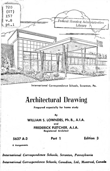
14architectural drawing,PART iX22 in. Lay off the outer lines with a pencil, as shown mFig. 3, making a rectangle measuring 15 in. X 20 h inside thislinedrawtheborderline.Layoutthefrom the trimmingpanels a, b, c, and d according to the dimensions shown onthe illustration. After all the lines have been drawn, measure thedimensions once more to make sure that they are correct andproceed with the exercise. All these lines should be drawn lightlyso as to be barely visible. Strengthen the border line with a firm,even pressure of the pencil point on the paper, The lines that aredrawn lightly are needed only as guides in laying out the drawingand can be easily erased when the drawing is finished.The panels a, b, c} and d of Plate I are to be filled in thefour exercises of Plate I. Exercise I is to be placed in panel a,Exercise II in panel b, Exercise III in panel c, and Exercise IVin panel d.The space between the upper border line and the panels is forthe title, as shown in the layout of Plate I given in Fig. 3.The space between the lower border and the trimming line isfor the student’s name and class letters and number, the date,the grade and the initials of the examiner. If the name andclass letters and number are omitted, the drawing cannot beidentified readily or perhaps not at all, and there is liable to bea delay in the return of the corrected plate.The four exercises are to be made first in pencil on transparentbond paper and then traced in ink again using transparent bondpaper. Both copies are then to be cut along the trimming lineshown in Fig. 3 and sent to the Schools for examination andcriticism. The character of both the pencil and the pen workwill be considered in giving a grade on the work.28. Plate I, Exercise I: Symbols for Materials.—In mak ing a drawing in which it is necessary to show several differentmaterials, and when it is desirable to make prints from thedrawing, these different materials are indicated by certain con ventional symbols as shown in Plate I, Exercise I. Thesesymbols vary in different offices, but the ones shown will befound satisfactory. On every working drawing there shouldARCHITECTURAL DRAWING, PART 1PLATE I, EXERCISE ISYMBOLSfob, MATERIALSIN PLAN § SECTIONV/MMWM».::IN ELEVATIONz&icjoPLASTltio PL:.’STmU-’T:}OK STUCCO----concreteH-: TERRA COTTAWOOD'A.mrnmmmEARTHRUBBLE STONE WALLmmmnnnmiiINSULATIONa/mmmmRQCIC-FACED ASHLAR;BiiiiiBiiiiiMiaiiiiffliiiiiiinSHEET METALPARTITIONS AND WALLSSHEET METAL;IWOOD AND PLASTER;PARTITIONS AND WALLSALTERNATE NORWOOD PLASTER PARTITIONSJSfWOOD BLOCKINGAND TIMBERSSTEEL BEAMS OVERjISTRUCTURAL STEELIN SECTIONnote: contractor shall?VERIFY ALL DIMENSIONSBEFORE PROCEEDING WITHTHE WORK AT THE BUILDING15
architectural drawing,16PART 1ARCHITECTURAL DRAWING, PART 1be a parallelogram containing all the symbols used in thatdrawing. This will prevent any misunderstanding of theirsignificance. In drawing these symbols on Plate I they shouldbe made exactly the same size as are those given in the illus tration. The note given at the bottom of Exercise I is generallyput on drawings so that the work of one contractor will fit thework done by another.PLATE I, EXERCISE IIaSINGLE WINDOW(c)HIGH WINDOWDOUBLE HUNGWINDOW(a) oSINGLE DOOR/ARCHED OPENING(d)DOUBLE ACTINGDOOR/ (f)a-Utoiiti)C A S E /A EN TW / N D OW*5OPENING INOPENING OUTNOTE TRENCH DOORS ARE SHOWNSAME AS CASEMENT WINDOWSSINGLE DOOR,IN BRICE WALLRAD. PADJATOPjT 3 Col. JOSec.36-669(3)(rn)DOUBLE SLIDING DOOPL-?lGDI(n)(k)m!2"X 17"mm//WAd77DOUBLE HUNG WINDOWIN BRICK/ WALL) (l)REGISTER.,JT1 WALL DUCT— l)/Q"x24"RtaSINGLE SLIDING DOORj)el77'1T1 L a(P)(S) COM3 COAL cGAS RANGE. *Md7777/V*FIRE----4-6''-----D CEMENT HEARTH-DREJ'U'E IE/**!f .MOVABLE.wRANGE AND BOILER 1201Scale; raniIPLACESHELVES .D r 234-5676I1I11 H—I17 \29. Plate I, Exercise II: Parts of Buildings.—A plan ismade up of lines, all of which are drawn to indicate parts ofbuildings. A series of the most common of these indications isgiven in this exercise. The arrangement of lines used to showvarious kinds of doors, windows, fireplaces, etc., are here shown,and by drawing these elementary parts of the plan the beginnerwill be familiar with them when he comes to make workingdrawings.In drawing these indications, they should be made at the scaleof inch to the foot. The scale at which they are shown is givenat the bottom of the illustration. The lines should be made asnearly as possible of the same thickness as those shown, and thesnappy, vigorous character of these lines should be copied. Thedimensions shown in the illustration are to be used as a guide inlaying out the various indications on the plate. The scale givenin the illustration should be ticked off on a strip of paper. Thisstrip of paper should then be used as a scale to measure off thevarious parts of the illustration that are not covered by dimen sions. These distances should be laid out on the drawing paperat i inch scale.30. Plate I, Exercise III: Plumbing Fixtures.—A seriesof indications that are used to show various plumbing fixtureson architects’ drawings is shown in Exercise III. Varioustypes of bathtubs, showers, wash basins, sinks, laundry tubs,water closets, etc. are given. As one or more of these indica tions are used on every plan, it is necessary to be familiar withthem all. The indications are to be drawn at J inch to the foot,the scale generally used in working drawings. The sizes ofthe fixtures are shown at the scale given at the foot of the illus trations.
ARCHITECTURAL DRAWING, PART 118ARCHITECTURAL DRAWING, PART 131. In drawing the bath in (a), Exercise III, first layout the lines of the partitions at a, the partitions being made 6inches in thickness. Draw the outside line of the tub next andthen the rectangle showing the inside lines of the bath. Drawthe small curved corners b freehand, so that these curved linesmeet the ends of the straight lines. A shower is indicated atc and a ring from which a curtain is susp
ARCHITECTURAL DRAWING, PART 1 ARCHITECTURAL DRAWING, PART 1 3 pencil and without the use of instruments. In laying out a working drawing, instruments such as are used in mechanical and geometrical drawing are employed, and harder pencils are used than those used in making the studies. Th