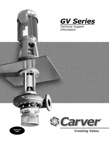
Transcription
JANUARY2004
GV SERIES – VERTICAL CANTILEVER AND SUMP PUMPS1.0JANUARY, 2004OverviewAll GV pumps are provided with the wet end,support column, bearing frame, motor mountingbracket and small top plate without dischargepiping as standard.The GV Series is Carver’s vertical pump linedesigned for moderate to high flow rates. Itincludes a cantilevered (GVC) tank-mounted unitwith optional top pull-out (GVT) and extendedlength, sump (GVS) versions.Standard options include discharge piping(standard, oversized and double oversized) withlarger top plates to accommodate the dischargepiping, 316 SS underliners (0.048” thickness) forcontamination and corrosion protection, inlet tailpipes and suction strainers.The GV is the natural evolution of the LHV, LHT,and LHS Series, which are now non-current. Andwhile the GV was designed for maximuminterchangeability with these pumps, it isnonetheless a new series and not necessarilyidentical to everything that preceded it.1.1Basic Hydraulic FeaturesStandard hydraulic features for the GV Series program are shown in the table below.Basic Hydraulic FeaturesGV Series PumpBasic SizeOrderingCodeGeneral Design FeaturesMax RPMMaxSolidsCasingVolutes1¼ x 1 x 7BA0.1871½ x 1¼ x 7BB0.2182½ x 2 x 7BC3 x 2½ x 3131½ x 1¼ x 10CA0.2182 x 1½ x 10CB0.2502½ x 2 x 10CC0.2183 x 2½ x 10CD4 x 3 x 10CE0.5625 x 4 x 10CF0.5006 x 5 x 10CG1.0002 x 1 x 11DA0.4374 x 2 x 11DB0.5001750DC5 x 4 x 11DD0.8138 x 6 x 11DE1.6252½ x 1½ x 13EA0.1312½ x 2 x 13EB0.313EC4 x 3 x 13ED5 x 4 x 13EE6 x 5 x 13EF8 x 6 x le0.4374 x 3 x 113 x 2½ x 131750Hydraulic alSingleFlangedQuadEnclosedDual0.3871750Q (GPM)@ FlangedEnclosedStandard Surface TreatmentAll iron castings are spot primed with red oxidesealer over any area exhibiting minor discolorationfrom rust or oxidation. Pumps handling fluidsabove 230 ºF can generally only be sold with priorapproval of Carver, and will be painted with twocoats of modified silicone alkyd resin, aluminumcolored, to a total of 2 mils dry film thickness.All GV Series components handling fluids less than230 ºF are painted to Carver Standard PA-001.This provides one coat of Carver Blue industrialalkyd metal enamel with a 3-5 mils dry filmthickness. All paint is applied over a clean, dry,bare metal surface.1
GV SERIES – VERTICAL CANTILEVER AND SUMP PUMPS1.3JANUARY, 2004Materials of Construction1.5Key GVS DataThe standard GV materials and materialspecifications are given in the table below:Many of the key GVS design parameters arespecified in the table below:Key Component MaterialsKey GVS DataComponentMaterialBearing FrameASTM A48, Class 30Cast ironASTM A48, Class 30316 SSASTM A744, Grade CF-8MCast ironASTM A48, Class 30316 SSASTM A744, Grade CF-8MCast ironASTM A48, Class 30Tin bronzeASTM B30, C90300CarbonAntimony filledImpellerLineshaft BearingO RingPipingShaftShaft sleeveSlingerSupport ColumnThrottle bushingUnderlinerElastomerVitonSteelASTM A106316 SSASTM A312Bearing FrameItemCast ironCasingMotor BracketSpecification43V - 143V - 2Max power (BHP) @ 1750 - 3500 RPM20 - 2075 - n/aRadial bearing typeJournalJournalThrust bearing type53075308Thrust bearing lubrication (standard)Line shaft lubrication (options)GreaseWater, oil or productShaft diameter @ coupling1.2501.250@ radial bearing1.5001.500@ thrust bearing1.3781.378@ impeller hub0.8751.250WR2 of Rotor (lb – in.) – 4’ columnfor each additional 2’ add7.988.203.383.38Steel - GVCASTM A108, Grade 121515.1015.10Steel - GVSASTM A434, Grade 414010” impellers56.6756.67316 SSASTM A276, UNS S3160011” impellers137.56137.56416 SSASTM A582, Type 41613” impellers233.74233.74Alloy 20ASTM A744, Grade CN-7ML10 bearing life (hrs) - radial50,000L10 bearing life (hrs) - thrust25,000ElastomerBuna NCompositeGlass filled vinyl esterSteelASTM A106316 SSASTM A269, Type 316Teflon15% glass, 5% molybdenum17-4 PH SSASTM A564, Type 630316 SSASTM A240, Type 316WR2 of Rotor (lb – in.) – 7” impellers1.6Selecting Vertical PumpsTo successfully select a GV pump the followinginformation must be known:a. Hydraulics1.4 Key GVC DataMany of the key GVC design parameters arespecified in the table below:Key GVC and GVT DataItemBearing Frame152015301540@ 1750 RPM2075150@ 3500 RPM20N/aN/aRadial bearing type207210312Thrust bearing type30753085611Max power (BHP)Thrust bearing lube (standard)Shaft diameter @ couplingb. Materials Grease1.2501.375@ radial bearing1.3781.9692.363@ thrust bearing1.3781.5752.1691.875@ impeller hub0.8751.2501.625Shaft diameter under sleeve1.0001.3751.750Shaft sleeve O.D.1.2501.7502.125L10 bearing life (hrs) - radial50,000L10 bearing life (hrs) - thrust25,000fluid to be pumpedflow ratetank fluid level (min, normal and max)discharge pressureviscosity (min, normal and max)temperature (min, normal and max)specific gravity (min, normal and max)NPSH availablevapor pressurec.Configurations / Accessories 2casing, piping and top plateshaftsimpellersthrottle bushingswear ringsdriver (speed, type, rating, manufacturer)coupling (torque, type, manufacturer)top plates (type, options)
GV SERIES – VERTICAL CANTILEVER AND SUMP PUMPS1.7JANUARY, 2004Vertical Pump Discharge HeadInadditiontothevarious(andoftencontradictory) published recommendations onthis, a simple rule of thumb often used is to setthe submergence depth to 6 times the nominalinlet size diameter of the pump (i.e., set H 6D).For smaller pumps less than 100 GPM this is oftensimplified to H 18”, and for larger pumps over1,200 GPM this is simplified to H 8D – seesketch below.While the flow required of a pump is generally wellknown, the total head against which it must pumpis often more difficult to determine. With verticalpumps one frequently overlooked item is that thepump discharge originates at the pump casingbelow the tank or pit surface, not at the dischargeflange at the tank top. Therefore, to correctlydetermine the discharge head required, theelevation between the actual pump dischargepoint and the distance to the tank or pit surface,and the resulting fluid friction losses encounteredalong this length of pipe, must also be considered.1.8The pump inlet, whether it is the pump casing oran extended inlet pipe, should be sized to adistance of 0.3 to 0.8 D to the tank bottom, with0.5 D considered optimal, where D is the nominalinlet diameter.NPSH & SubmergenceThis is important because if this inlet to tankbottom distance is too great, the submergencedepth is lessened. On the other hand, if thedistance is too small, debris and other foreignmatter on the tank bottom can be drawn in to thepump, in effect making the pump a vacuumcleaner for the tank.The minimum net positive suction head (NPSH)required is the net amount of hydraulic energyabove vapor pressure needed to overcomeelevation and friction losses and deliver fluid intothe eye of the impeller.NPSH is generallyunderstood with horizontal pumps, but withvertical pumps one other related consideration isthe concept of submergence. Submergence isthe height of a fluid above the pump’s inlet, orconversely, the depth of the vertical pump’s inletbelow the fluid surface. Submergence is not thesame as NPSH, and it must always be largeenough to maintain sufficient NPSH available andprevent vortexing.When a surface vortex develops in a vertical pumpinstallation, air is pulled down from the fluidsurface into the pump inlet.This in turn can be a serious problem, and someof its consequences are: rotor assembly imbalance and vibrationaccelerated wear due to dry runningaccelerated wear due to hydraulic shockloads as the air passes through the pumperratic performance, with loss of flow andheadThis last point is often overlooked, since airentrainment as little as a one percent by volumewill produce a noticeable drop-off in pumpperformance, and a two percent by volume airentrainment on the inlet can reduce the pumpflow rate by as much as 10%.Lastly, vortex breakers in the form of inlet baffles,weirs and/or suction strainers can be veryeffective in preventing vortices from forming inthe system. Therefore, it is recommended thatevery GV pump be equipped with a suctionstrainer. When pumping fluids over 1,000 SSU,the finest strainer screen practical is about 1/8"perforation. It is also advisable to monitor thestrainer with a differential pressure gauge orswitch, since a clogged strainer will cause a pumpto cavitate.The two most common conditions for vortexformation are insufficient submergence depth andexcessive suction piping fluid velocity. Systemdesign guidelines for overcoming this arepublished by the Hydraulic Institute and others.3
GV SERIES – VERTICAL CANTILEVER AND SUMP PUMPS1.9JANUARY, 2004A Typical GV Series Specification - (Specifier’s options in parentheses)Each pump shall be a vertical, end suction, centrifugal pump capable of developing (500) US GPMat a total head of (200) feet when pumping (water) at a temperature of (100) F with a fluidspecific gravity of (1.00) without the use of special clearances, materials, or other internal orexternal modifications. In meeting these hydraulic conditions the pump shall have an NPSHrequirement of not more than (10) feet and a hydraulic operating efficiency at the normal dutypoint of at least (70.0)% as defined by the Hydraulic Institute Level A requirements, whichincludes all mechanical seal, lineshaft bearing and/or throttle bushing losses.The pump shall include separate liquid end, support column and bearing frame sections for ease ofmaintenance. The liquid end shall be cast iron (316 stainless steel), with all components below thetop plate surface fully compatible with the temperature, corrosion and abrasion properties of thefluid being pumped.The impellers shall be precision cast iron (316stainless steel) and positively keyed to the pump driveshaft for more positive driving and to prevent theimpeller from spinning off the shaft and damagingitself and/or the pump casing in the event ofaccidental reverse rotation. As a further means ofassuring longer component life, all impellers shall bedynamically balanced in accordance with ISO G2.5guidelines.The bearing frame shall be located above the topmounting surface for ease of access. It shall consist ofa minimum of two matched grease-lubricated ballbearings to handle all radial and axial loads. Thethrust bearing shall have a minimum L10 life of 25,000hours and the radial bearing shall have a minimum L10life of 50,000 hours.For added reliability, the bearings shall be protectedfrom any fluid vapors by means of a spring-loaded lipseal. The bearings and shaft shall be designed toprovide minimum deflection throughout the entirerange of pump operation.For optimum efficiency and to assure long life withoutdegradation in performance over time, the bearingframe assembly shall have the means of disassembling the pump or otherwise removing it fromthe system.The pump shall have a replaceable Teflon throttle bushing at the outboard (impeller) end and theoption for a hardened 17-4 stainless steel throttle bushing with a hardened 416 stainless steelshaft sleeve when pumping fluids with dirt or abrasives present. In all cases, the throttle bushingshall not be used as a bearing surface, and the maximum deflection at the throttle bushing shallnot exceed 0.010 inches. All extended length sump pumps shall have as a minimum one lineshaftbearing for each 4.0 foot of column length. The lineshaft bearing shall be bronze (carbon) andcapable of being either permanently grease lubricated or externally lubricated and flushed byeither oil, water or the fluid being pumped.The pump shall be supplied complete with an electric motor, top plate, (discharge piping), (inletstrainer), coupling and coupling guard. It shall be capable of operating throughout the entirerange of its performance curve without exceeding the nameplate horsepower rating of its motor.The pump shall be a heavy-duty industrial design, GV Series as manufactured by the Carver PumpCompany of Muscatine, Iowa, or approved ISO-9001 certified, United States manufactured equal.4
GV SERIES – VERTICAL CANTILEVER AND SUMP PUMPS1.10JANUARY, 2004Comments, Clarifications and/or Exceptions to API Standard 610, 8th EditionSection 1 – GeneralNoneSection 2 - Basic Design2.1.182.1.19Cooling Jacket Cleaning and Flushing – ClarificationCooling jackets, when provided, must be drained and flushed through the cooling jacket inlet andoutlet connections. The jackets must be removed for further cleaning.2.1.26Vibration - CommentVibration criteria used for the GV Series are the Hydraulic Institute Standards for vertical sumppumps:a.b.c.1200 RPM - 4.0 mils peak-peak displacement1800 RPM - 3.0 mils peak-peak displacement3600 RPM - 1.8 mils peak-peak displacementHI criteria calls for taking vibration measurements at the top motor bearing. Vibration at thepump thrust bearing will be significantly less. Any requirements for lower than H.I. standards willbe examined on a case by case basis.2.2.1Pressure Vessel Stresses – CommentPressure containing parts are the pump casing, suction cover, discharge elbow, and dischargepipe. These pressure containing components are designed in accordance to ASME Section IIIincluding a 1/8" corrosion allowance. ASME Section VIII regarding welding of fabricated pressurecomponents does not apply.2.2.12Jackscrews - ClarificationJackscrews are not required for vertical sump pumps per API-610 Paragraph 5.3.1.1.2.2.13.3Internal Bolting – ClarificationInternal bolting on cast iron units is carbon steel. 316 SS bolts must be used to be fully resistantwhen pumping corrosive fluids. For all 316 SS bolting below the top plate refer to factory for priceadder.2.3.1.2Flush connections – ExceptionFlush connections are 1/4" NPT as standard. For larger flush connections refer to factory for priceadder.2.3.3.4Auxiliary Connections – ExceptionWe do not weld fittings to the casings. If a line shaft bearing flush from the casing is supplied, itwill be a threaded compression fitting.2.4External Nozzle Forces and Moments – ExceptionThe orientations for vertical sump pumps are not specifically addressed in the API-610, 8thedition. This section is very difficult to apply to a GVS series.2.5.15.3.2.1Impeller Design – ExceptionImpellers on the 7” & 10” GVS’s are semi-open as standard. For feasibility of supplying enclosedimpellers on GVS’s refer to factory.2.5.75.3.11.8Shaft Run Out - ClarificationNominal run out at the stuffing box will be 0.004" TIR or less when operating under normaloperating circumstances.2.6.1Wear Rings - ExceptionWear rings are not applicable for semi-open impellers.2.7Mechanical Shaft Seals – ClarificationThe GVS Series is sealless design. For high temperatures and/or vapor proof applications, apacked box is available. For mechanically sealed pumps refer to factory for selection and pricing.2.7.3.1Mechanical Shaft Seals – ClarificationWhen mechanical seals are provided, the driver must be removed to replace the seal.5
GV SERIES – VERTICAL CANTILEVER AND SUMP PUMPSJANUARY, 20042.7.3.62.7.3.8Mechanical Shaft Seals – ClarificationSeal dimensions and chamber bores will be per the seal manufacturers’ recommendations.2.7.3.182.7.3.20Float Bushings and Throttle Bushings – ExceptionSeals on the GVS do not see the pumpage. Throat bushings and throttle bushings 2.7.3.21 areonly required on inside seals to contain the flush fluid and contain it in the stuffing box area.2.8.4.1Balancing – ClarificationStandard balancing on the GVS Series is to ISO G6.3. For optional G2.5 balancing refer to factoryfor price adder.2.9.1.5Thrust Bearings - ExceptionAll GVS Series thrust bearings are Duplex 5300 series2.9.2.1Bearing Housings – ClarificationThe motor must be removed to change bearings.2.9.2.5Bearing Housings Materials – ExceptionMotor supports and bearing housings are cast iron as standard.2.9.2.6Bearing Housing Labyrinth Seals Materials – ExceptionThe lower bearing shell seal on the GVS Series is a lip seal.2.9.2.10Bearing Housing Vibration Measurements – ExceptionThe standard bearing housing shell is not dimpled. For dimpled bearing housing shell refer tofactory for price adder.2.10Lubrication – ExceptionThe thrust bearing is grease lubricated. For optional oil lubrication refer to factory for price adder.2.11.1.5Material Identification – ClarificationThe customer must specify when low carbon grades are required.adders.Refer to factory for price2.11.3.22.11.3.32.11.3.4.22.11.3.5.5Welding Procedures – ExceptionTo comply with these welding procedure refer to factory for price adder.2.11.3.5.1Flange Welding – ClarificationThe GVS discharge flange at the top will be welded. The submerged suction flange is a non-pipedcasting integral to the pump casing.2.12.2Nameplates – ClarificationCustom nameplates require information from the customer - refer to factory for price adders.Section 3 - Accessories3.2.23.2.10Spacer Couplings – ExceptionSpacer couplings serve no practical advantage with vertical sump pumps, and so are not offered.3.2.4Coupling Hubs – ClarificationCoupling hubs are supplied with clearance fits, per Paragraph 5.3.11.11.3.2.63.2.7Coupling Balancing – ClarificationThis section requires API couplings. For suitable API coupling refer to factory for price adder.Section 4 - Inspection, Testing, and Preparation for Shipment5.3.7.23.2.11Coupling Alignment - ExceptionThe normal procedure is to ship the pump with the motor off and the coupling separate.6
GV SERIES – VERTICAL CANTILEVER AND SUMP PUMPSJANUARY, 20044.3.1.14.3.4.1NPSH Tests – ClarificationNPSH tests cannot be performed on vertical sump pumps.4.3.2.1Hydrostatic Tests – ClarificationThe standard hydrotest is for the casing only. To hydrotest the suction cover and discharge piping(by definition the pressure casing components), refer to factory for price adder.4.3.2.3Chloride Content of Test Water – ExceptionAll tests are done using the local water supply and cannot guarantee a chloride content of 50 PPMor less.4.4.3.44.4.3.5Surface Rust Prohibitor – ClarificationWe do not provide a surface rust prohibitor or internal surface protection as standard. For surfacerust prohibitor or internal surface protection refer to factor for price adder.4.4.3.6Standard Flange Covering – ClarificationThe standard flange cover for the GVS is wafer board secured to the flange. For metal coveringsrefer to factory for price adder.Section 5 - Specific Pump Types5.3.2.2Shaft Straightness – ExceptionOur standard shaft straightness is 0.006”. For shafts that comply with 0.003" maximum totalindicated run out (TIR) refer to factory for price adder.5.3.5.1Lineshaft Bearing Spacing – ClarificationThe maximum spacing between lineshaft bearings in a GVS column is 48”.GVS Lineshaft Bearing Flush and Lubrication OptionsFig. 1Greased for LifeBronze(standard)orcarbon(optional) bearings, sealed at bothends, flush connection drilled, tappedand plugged, with no external flushFig. 2Water or Product LubedBronze (standard) or carbon (optional)bearings, open at both ends. Productflush from point on pump discharge,water flush from external source (byothers)7Fig. 3Oil LubricatedBronze (standard) or carbon (optional)bearings, sealed at both ends, oilpumped down from external source(by others)
GV SERIES – VERTICAL CANTILEVER AND SUMP PUMPSJANUARY, 20041.11 GV Series Bearing Frame DesignationsThe standard GV bearing frames can be seen in the chart above. The standard GVC setting is 12 incheslong, giving a 12 inch drop between the bottom of the mounting plate and back of the pump casing whilethe extended column setting has a 24 inch drop between the bottom of the mounting plate and back ofthe pump casing.7” impellers1520 Bearing FrameUp to 3500 RPM / 20 HP1530 Bearing FrameUp to 1750 RPM / 75 HP1540 Bearing FrameUp to 1750 RPM / 10” impellersExtendedSetting11” impellers13” impellers10” impellersExtendedSetting11” impellers13” impellersExtendedSetting13” impellersNote: 1530 and 1540 bearing frame motor brackets omitted for clarity.1.12 GV Series Hydraulic Coverage and Performance by Individual SizeGV hydraulic performance extends to flows of 2500 GPM at 1750 RPM with twenty five sizes in cast iron,316 SS fitted cast iron, or all 316 stainless steel. Pumps with 7” and 10” impellers and dischargeconnections 2” and smaller are provided with NPT connections. All others have ANSI flange connections.Replaceable 17-4 PH front and rear wear rings are standard with all stainless units with enclosed impellers(i.e., 11” diameter and above) as standard, except for the sizes 2 x 1 x 11 and 2½ x 1½ x 13, which havefront wear rings only.8
GV SERIES – VERTICAL CANTILEVER AND SUMP PUMPSJANUARY, 2004Hydraulic Performance - 7 Inch ImpellersNotes:1.2.3.Above data is based on 1.0 sp. gr. water at ambient temperature and pressure in accordance with Hydraulic Institute guidelines.Impeller diameters between minimum and maximum shown are available in 1/8 inch increment trims.For special GVS requirements at start up refer to Table 1.13, page 23.9
GV SERIES – VERTICAL CANTILEVER AND SUMP PUMPSJANUARY, 2004Hydraulic Performance - 7 Inch ImpellersNotes:1.2.3.Above data is based on 1.0 sp. gr. water at ambient temperature and pressure in accordance with Hydraulic Institute guidelines.Impeller diameters between minimum and maximum shown are available in 1/8 inch increment trims.For special GVS requirements at start up refer to Table 1.13, page 23.10
GV SERIES – VERTICAL CANTILEVER AND SUMP PUMPSJANUARY, 2004Hydraulic Performance - 7 Inch ImpellersNotes:1.Above data is based on 1.0 sp. gr. water at ambient temperature and pressure in accordance with Hydraulic Institute guidelines.2.3.Impeller diameters between minimum and maximum shown are available in 1/8 inch increment trims.For special GVS requirements at start up refer to Table 1.13, page 23.11
GV SERIES – VERTICAL CANTILEVER AND SUMP PUMPSJANUARY, 2004Hydraulic Performance - 7 Inch ImpellersNotes:1.Above data is based on 1.0 sp. gr. water at ambient temperature and pressure in accordance with Hydraulic Institute guidelines.2.3.Impeller diameters between minimum and maximum shown are available in 1/8 inch increment trims.For special GVS power requirements at start up refer to Table 1.13, page 23.12
GV SERIES – VERTICAL CANTILEVER AND SUMP PUMPSJANUARY, 2004Hydraulic Performance - 7 Inch ImpellersNotes:1.2.3.Above data is based on 1.0 sp. gr. water at ambient temperature and pressure in accordance with Hydraulic Institute guidelines.Impeller diameters between minimum and maximum shown are available in 1/8 inch increment trims.For special GVS power requirements at start up refer to Table 1.13, page 23.13
GV SERIES – VERTICAL CANTILEVER AND SUMP PUMPSJANUARY, 2004Hydraulic Performance - 10 Inch ImpellersNotes:1.2.3.Above data is based on 1.0 sp. gr. water at ambient temperature and pressure in accordance with Hydraulic Institute guidelines.Impeller diameters between minimum and maximum shown are available in 1/8 inch increment trims.For special GVS power requirements at start up refer to Table 1.13, page 23.14
GV SERIES – VERTICAL CANTILEVER AND SUMP PUMPSJANUARY, 2004Hydraulic Performance - 10 Inch ImpellersNotes:1.Above data is based on 1.0 sp. gr. water at ambient temperature and pressure in accordance with Hydraulic Institute guidelines.2.3.Impeller diameters between minimum and maximum shown are available in 1/8 inch increment trims.For special GVS power requirements at start up refer to Table 1.13, page 23.15
GV SERIES – VERTICAL CANTILEVER AND SUMP PUMPSJANUARY, 2004Hydraulic Performance - 10 Inch ImpellersNotes:1.2.3.Above data is based on 1.0 sp. gr. water at ambient temperature and pressure in accordance with Hydraulic Institute guidelines.Impeller diameters between minimum and maximum shown are available in 1/8 inch increment trims.For special GVS power requirements at start up refer to Table 1.13, page 23.16
GV SERIES – VERTICAL CANTILEVER AND SUMP PUMPSJANUARY, 2004Hydraulic Performance - 10 and 11 Inch ImpellersNotes:1.2.3.Above data is based on 1.0 sp. gr. water at ambient temperature and pressure in accordance with Hydraulic Institute guidelines.Impeller diameters between minimum and maximum shown are available in 1/8 inch increment trims.For special GVS power requirements at start up refer to Table 1.13, page 23.17
GV SERIES – VERTICAL CANTILEVER AND SUMP PUMPSJANUARY, 2004Hydraulic Performance - 11 Inch ImpellersNotes:1.2.3.Above data is based on 1.0 sp. gr. water at ambient temperature and pressure in accordance with Hydraulic Institute guidelines.Impeller diameters between minimum and maximum shown are available in 1/8 inch increment trims.For special GVS power requirements at start up refer to Table 1.13, page 23.18
GV SERIES – VERTICAL CANTILEVER AND SUMP PUMPSJANUARY, 2004Hydraulic Performance - 11 Inch ImpellersNotes:1.2.3.Above data is based on 1.0 sp. gr. water at ambient temperature and pressure in accordance with Hydraulic Institute guidelines.Impeller diameters between minimum and maximum shown are available in 1/8 inch increment trims.For special GVS power requirements at start up refer to Table 1.13, page 23.19
GV SERIES – VERTICAL CANTILEVER AND SUMP PUMPSJANUARY, 2004Hydraulic Performance - 13 Inch Impellers @ 1750 RPMNotes:1.2.3.Above data is based on 1.0 sp. gr. water at ambient temperature and pressure in accordance with Hydraulic Institute guidelines.Impeller diameters between minimum and maximum shown are available in 1/8 inch increment trims.For special GVS power requirements at start up refer to Table 1.13, page 23.20
GV SERIES – VERTICAL CANTILEVER AND SUMP PUMPSJANUARY, 2004Hydraulic Performance - 13 Inch ImpellersNotes:1.2.3.Above data is based on 1.0 sp. gr. water at ambient temperature and pressure in accordance with Hydraulic Institute guidelines.Impeller diameters between minimum and maximum shown are available in 1/8 inch increment trims.For special GVS power requirements at start up refer to Table 1.13, page 23.21
GV SERIES – VERTICAL CANTILEVER AND SUMP PUMPSJANUARY, 2004Hydraulic Performance - 13 Inch ImpellersNotes:1.2.3.Above data is based on 1.0 sp. gr. water at ambient temperature and pressure in accordance with Hydraulic Institute guidelines.Impeller diameters between minimum and maximum shown are available in 1/8 inch increment trims.For special GVS power requirements at start up refer to Table 1.13, page 23.22
GV SERIES – VERTICAL CANTILEVER AND SUMP PUMPSJANUARY, 2004Hydraulic Performance - 13 Inch ImpellersNotes:1.Above data is based on 1.0 sp. gr. water at ambient temperature and pressure in accordance with Hydraulic Institute guidelines.2.3.Impeller diameters between minimum and maximum shown are available in 1/8 inch increment trims.For special GVS power requirements refer to Table 1.13 below.1.13Special Power Considerations for the GVSTo allow for lineshaft bearing friction losses sometimes encountered in start up (i.e., potentially dry run)situations, we recommend the following power requirements be added to those shown on the HydraulicPerformance curves.GVS Dry Lineshaft Bearing Friction LossesColumn DepthAdded Dry Start Up Losses4 to 10 ft.0.50 BHP10 to 16 ft.0.75 BHP16 to 20 ft.1.00 BHPover 20 ft.1.25 BHP23
GV SERIES – VERTICAL CANTILEVER AND SUMP PUMPSJANUARY, 2004GVC - 7” and 10” Impeller Sizes (Without Discharge Piping)A4 X 0.69 THRU1.251.25A/2A/2APCF.52MAX. LIQUID LEVELFGDISCHARGE CONNECTION:1" - 2": FNPT2.5" - 4": 125# FF-C.I.150# FF-316 SSKHPump DimensionsPump SizeFAStandardExtendedSUCTION CONNECTION:1.25" - 2.5": FNPT3" - 5": 125# FF-C.I.150# FF-316 SSMotor DimensionsGHKBearingFrameNEMA MotorFrameCFP7.41¼ x 1 x 718.014.826.82.74.33.8143 TC27.01½ x 1¼ x 718.014.426.42.84.54.0145 TC28.07.42½ x 2 x 718.014.326.33.75.04.1182 TC28.59.53 x 2½ x 724.014.326.34.05.84.3184 TC29.59.54x3x724.014.526.54.86.04.5213 TC31.011.05x4x724.014.426.45.07.54.8215 TC32.011.01½ x 1¼ x 1018.014.226.23.36.05.3254 TC34.013.02 x 1½ x 1018.014.326.33.56.05.4256 TC35.013.02½ x 2 x 1018.014.426.44.36.35.5284 TC41.015.03 x 2½ x 1024.014.426.44.77.05.8286 TC43.015.04 x 3 x 1024.014.426.34.67.06.05 x 4 x 1024.014.426.44.78.56.56 x 5 x 1030.015.927.95.88.47.615201520Note: NEMA frames 284 / 286 TC available15301.All dimensions in inches, all tolerances /- 0.125 inch.2.All motor dimensions are approximate.3.Not valid for construction unless certified.24with size 1530 bearing frame onlyDwg: SP-GV-1, Rev: 0
GV SERIES – VERTICAL CANTILEVER AND SUMP PUMPSJANUARY, 2004GVC - 7” and 10” Impeller Sizes (With Discharge Piping)A4 X 0.69 THRU1.251.25DA/2CBPDISCHARGE150# R.F. FLG.CF6 .13.52MAX. LIQUID LEVELFGSUCTION CONNECTION:1.25" - 2.5": FNPT3" - 5": 125# FF-C.I.150# FF-316 SSENote: Minimum discharge pipe size is 2”Pump DimensionsPump SizeDischarge PipeABStandardOversizedDbl. O’size1x1x722218.024.01½ x 1¼ x 722218.024.02½ x 2 x 722½318.03 x 2½ x 72½344x3x7345x4x7451½ x 1¼ x 1022 x 1½ x 10DCFEStandardOversizedDbl. 024.0222½18.02½ x 2 x 1022½33 x 2½ x 102½34 x 3 x 1035 x 4 x 1046 x 5 x 9.016.014.426.44.76830.045.013.022
GV SERIES - VERTICAL CANTILEVER AND SUMP PUMPS JANUARY, 2004 1 1.0 Overview The GV Series is Carver's vertical pump line designed for moderate to high flow rates. It includes a cantilevered (GVC) tank-mounted unit with optional top pull-out (GVT) and extended length, sump (GVS) versions. The GV is the natural evolution of the LHV, LHT,
