Transcription
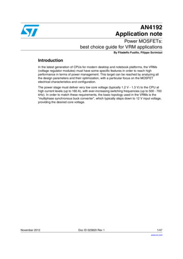
AN4192Application notePower MOSFETs:best choice guide for VRM applicationsBy Filadelfo Fusillo, Filippo ScrimizziIntroductionIn the latest generation of CPUs for modern desktop and notebook platforms, the VRMs(voltage regulator modules) must have some specific features in order to reach highperformance in terms of power management. This target can be reached by analyzing allthe design parameters and their optimization, with a particular focus on the MOSFETelectrical characteristics and configuration.The power stage must deliver very low core voltage (typically 1.2 V - 1.3 V) to the CPU athigh current levels (up to 160 A), with ever-increasing switching frequencies (up to 500 - 700kHz). In order to match these requirements, the basic topology used in the VRMs is the“multiphase synchronous buck converter”, which typically steps down to 12 V input voltage,providing the desired core voltage.November 2012Doc ID 023820 Rev 11/47www.st.com
ContentsAN4192Contents1Synchronous buck converter: a brief introduction . . . . . . . . . . . . . . . . 62High-side MOSFET selection . . . . . . . . . . . . . . . . . . . . . . . . . . . . . . . . . . 932.0.1QG,SW and fSW impact on the efficiency . . . . . . . . . . . . . . . . . . . . . . . . 102.0.2QG,SW impact on the HS switching behavior . . . . . . . . . . . . . . . . . . . . . 122.1RDS(on) and conduction losses minimization . . . . . . . . . . . . . . . . . . . . . . 142.2Gate drive network optimization . . . . . . . . . . . . . . . . . . . . . . . . . . . . . . . . 15Low-side FET selection . . . . . . . . . . . . . . . . . . . . . . . . . . . . . . . . . . . . . 203.1RDS(on) and conduction losses minimization . . . . . . . . . . . . . . . . . . . . . 203.2CGD (Miller capacitance) . . . . . . . . . . . . . . . . . . . . . . . . . . . . . . . . . . . . . 213.3LS body-drain diode Qrr (reverse recovery charge) . . . . . . . . . . . . . . . . . 243.4RG and LS gate-source bouncing . . . . . . . . . . . . . . . . . . . . . . . . . . . . . . 303.5RC snubber network settings . . . . . . . . . . . . . . . . . . . . . . . . . . . . . . . . . . 373.6Phase node spike - VCORE relationship . . . . . . . . . . . . . . . . . . . . . . . . . . 424Conclusion . . . . . . . . . . . . . . . . . . . . . . . . . . . . . . . . . . . . . . . . . . . . . . . . 445Bibliography . . . . . . . . . . . . . . . . . . . . . . . . . . . . . . . . . . . . . . . . . . . . . . 456Revision history . . . . . . . . . . . . . . . . . . . . . . . . . . . . . . . . . . . . . . . . . . . 462/47Doc ID 023820 Rev 1
AN4192List of tablesList of tablesTable 1.Table 2.Table 3.Table 4.Table 5.HS FETs electrical parameters comparison . . . . . . . . . . . . . . . . . . . . . . . . . . . . . . . . . . . . 11MOSFET electrical parameters . . . . . . . . . . . . . . . . . . . . . . . . . . . . . . . . . . . . . . . . . . . . . 15Main electrical parameters . . . . . . . . . . . . . . . . . . . . . . . . . . . . . . . . . . . . . . . . . . . . . . . . . 21Device electrical parameters . . . . . . . . . . . . . . . . . . . . . . . . . . . . . . . . . . . . . . . . . . . . . . . 26Revision history . . . . . . . . . . . . . . . . . . . . . . . . . . . . . . . . . . . . . . . . . . . . . . . . . . . . . . . . . 46Doc ID 023820 Rev 13/47
List of figuresAN4192List of figuresFigure 1.Figure 2.Figure 3.Figure 4.Figure 5.Figure 6.Figure 7.Figure 8.Figure 9.Figure 10.Figure 11.Figure 12.Figure 13.Figure 14.Figure 15.Figure 16.Figure 17.Figure 18.Figure 19.Figure 20.Figure 21.Figure 22.Figure 23.Figure 24.Figure 25.Figure 26.Figure 27.Figure 28.Figure 29.Figure 30.Figure 31.Figure 32.Figure 33.Figure 34.Figure 35.Figure 36.Figure 37.Figure 38.Figure 39.Figure 40.Figure 41.Figure 42.Figure 43.Figure 44.Figure 45.Figure 46.Figure 47.Figure 48.4/47Synchronous buck converter simplified schematic . . . . . . . . . . . . . . . . . . . . . . . . . . . . . . . . 5HS/LS gate-source voltages . . . . . . . . . . . . . . . . . . . . . . . . . . . . . . . . . . . . . . . . . . . . . . . . . 6Multiphase synchronous buck converter schematic . . . . . . . . . . . . . . . . . . . . . . . . . . . . . . . 7Gate charge waveform . . . . . . . . . . . . . . . . . . . . . . . . . . . . . . . . . . . . . . . . . . . . . . . . . . . . . 82-phase synchronous buck converter schematic . . . . . . . . . . . . . . . . . . . . . . . . . . . . . . . . . 9Efficiency comparison @ 440 kHz . . . . . . . . . . . . . . . . . . . . . . . . . . . . . . . . . . . . . . . . . . . 10Efficiency @ 300 kHz . . . . . . . . . . . . . . . . . . . . . . . . . . . . . . . . . . . . . . . . . . . . . . . . . . . . . 10MOSFET equivalent circuit during Miller plateau . . . . . . . . . . . . . . . . . . . . . . . . . . . . . . . . 11MOS1 (CGD 76 pF) - HS turn-off waveforms . . . . . . . . . . . . . . . . . . . . . . . . . . . . . . . . . . 12MOS1 (CGD 150 pF) - HS turn-off waveforms . . . . . . . . . . . . . . . . . . . . . . . . . . . . . . . . . 12Single-phase synchronous buck converter schematic . . . . . . . . . . . . . . . . . . . . . . . . . . . . 13Efficiency comparison @ Vout 1.25 V . . . . . . . . . . . . . . . . . . . . . . . . . . . . . . . . . . . . . . . 14HS turn-off . . . . . . . . . . . . . . . . . . . . . . . . . . . . . . . . . . . . . . . . . . . . . . . . . . . . . . . . . . . . . 15HS turn-on (phase node spike) . . . . . . . . . . . . . . . . . . . . . . . . . . . . . . . . . . . . . . . . . . . . . . 15Typical phase node waveform (without RC snubber network) . . . . . . . . . . . . . . . . . . . . . . 15Asymmetric HS gate drive circuit . . . . . . . . . . . . . . . . . . . . . . . . . . . . . . . . . . . . . . . . . . . . 163-phase synchronous buck converter . . . . . . . . . . . . . . . . . . . . . . . . . . . . . . . . . . . . . . . . . 16Phase node waveform - standard configuration . . . . . . . . . . . . . . . . . . . . . . . . . . . . . . . . . 17Phase node waveform - HS asymmetric gate drive configuration . . . . . . . . . . . . . . . . . . . 17Efficiency comparison @ Vout 1.26 V . . . . . . . . . . . . . . . . . . . . . . . . . . . . . . . . . . . . . . . 18Efficiency vs. Iout @ Vout 1.25 V . . . . . . . . . . . . . . . . . . . . . . . . . . . . . . . . . . . . . . . . . . . 20Buck converter schematic. . . . . . . . . . . . . . . . . . . . . . . . . . . . . . . . . . . . . . . . . . . . . . . . . . 21Impact of the stray inductances on the phase node ringing . . . . . . . . . . . . . . . . . . . . . . . . 21Low-CRSS LS FET phase node waveform @ 80 A . . . . . . . . . . . . . . . . . . . . . . . . . . . . . . . 22High-CRSS LS FET phase node waveform @ 80 A . . . . . . . . . . . . . . . . . . . . . . . . . . . . . . 23Single-phase synchronous buck converter . . . . . . . . . . . . . . . . . . . . . . . . . . . . . . . . . . . . . 24Reverse recovery charge waveforms . . . . . . . . . . . . . . . . . . . . . . . . . . . . . . . . . . . . . . . . . 24Body-drain diode reverse recovery current. . . . . . . . . . . . . . . . . . . . . . . . . . . . . . . . . . . . . 25Single-phase synchronous buck converter schematic . . . . . . . . . . . . . . . . . . . . . . . . . . . . 26Standard LS waveforms @ 20 A . . . . . . . . . . . . . . . . . . . . . . . . . . . . . . . . . . . . . . . . . . . . 26LS with monolithic Schottky diode waveforms @ 20 A . . . . . . . . . . . . . . . . . . . . . . . . . . . . 272-phase synchronous buck converter schematic . . . . . . . . . . . . . . . . . . . . . . . . . . . . . . . . 28Monolithic Schottky impact on the efficiency @ 610 kHz . . . . . . . . . . . . . . . . . . . . . . . . . . 28LS FET during HS turn-on . . . . . . . . . . . . . . . . . . . . . . . . . . . . . . . . . . . . . . . . . . . . . . . . . 29Low ext. RG (2 Ω) LS FET waveforms during HS turn-on . . . . . . . . . . . . . . . . . . . . . . . . . 30High ext. RG (4.7 Ω) LS FET waveforms during HS turn-on. . . . . . . . . . . . . . . . . . . . . . . . 30Low RG,LS(INT) (1.5 Ω) LS FET waveforms @ full load . . . . . . . . . . . . . . . . . . . . . . . . . . . . 31High RG,LS(INT) (3 Ω) LS FET waveforms @ full load . . . . . . . . . . . . . . . . . . . . . . . . . . . . . 312-phase synchronous buck converter . . . . . . . . . . . . . . . . . . . . . . . . . . . . . . . . . . . . . . . . . 32Low RG,LS(INT) (1.3 Ω) waveforms @ full load . . . . . . . . . . . . . . . . . . . . . . . . . . . . . . . . . . 33High RG,LS(INT) waveforms @ full load . . . . . . . . . . . . . . . . . . . . . . . . . . . . . . . . . . . . . . . . 33Simplified LS FET circuit. . . . . . . . . . . . . . . . . . . . . . . . . . . . . . . . . . . . . . . . . . . . . . . . . . . 34Single-phase synchronous buck converter schematic . . . . . . . . . . . . . . . . . . . . . . . . . . . . 341 x LS vs. 2 x LS (LS G-S ringing improvement) . . . . . . . . . . . . . . . . . . . . . . . . . . . . . . . . 35LS gate-source bouncing reduction for bigger die size LS FETs . . . . . . . . . . . . . . . . . . . . 35LS FET with RC snubber network . . . . . . . . . . . . . . . . . . . . . . . . . . . . . . . . . . . . . . . . . . . 36Phase node waveform and fRING evaluation . . . . . . . . . . . . . . . . . . . . . . . . . . . . . . . . . . . 37Original configuration waveforms @ 20 A . . . . . . . . . . . . . . . . . . . . . . . . . . . . . . . . . . . . . 38Doc ID 023820 Rev 1
AN4192Figure 49.Figure 50.Figure 51.Figure 52.Figure 53.Figure 54.Figure 55.Figure 56.List of figuresRG,HS(EXT) 0 Ω - RG,HS(EXT) 1.8 Ω/original snubber waveforms @ 20 A. . . . . . . . . . . . 38RG,HS(EXT) 2.2 Ω - RG,HS(EXT) 1.8 Ω/ original snubber waveforms @ 20 A. . . . . . . . . . 39RG,HS(EXT) 2.2 Ω - RG,HS(EXT) 1.8 Ω/ RSNUB 1 Ω waveforms @ 20 A . . . . . . . . . . . . 40Phase node improvement . . . . . . . . . . . . . . . . . . . . . . . . . . . . . . . . . . . . . . . . . . . . . . . . . 403-phase synchronous buck converter . . . . . . . . . . . . . . . . . . . . . . . . . . . . . . . . . . . . . . . . . 41Phase node waveform @ 2.5 V . . . . . . . . . . . . . . . . . . . . . . . . . . . . . . . . . . . . . . . . . . . . . 42Phase node waveform @ 3.3 V . . . . . . . . . . . . . . . . . . . . . . . . . . . . . . . . . . . . . . . . . . . . . 42Phase node spike - VOUT chart . . . . . . . . . . . . . . . . . . . . . . . . . . . . . . . . . . . . . . . . . . . . . 43Doc ID 023820 Rev 15/47
Synchronous buck converter: a brief introduction1AN4192Synchronous buck converter: a brief introductionThe basic topology of a single-phase synchronous buck converter (SBC) is shown inFigure 1; SW1 is the main (or high-side) FET, SW2 is the synchronous (or low-side) FET, Land C are the output filters.Figure 1.Synchronous buck converter simplified schematicAM16445V1Comparing this topology to the standard buck converter, the main difference is thesynchronous rectifier (SW2) instead of the free-wheeling diode; as VDS(on) VF,DIODE, astrong reduction of the ON-state losses is guaranteed.SW1 and SW2 are driven in a “synchronous” way: in other words, the control IC generatesthe gate driving signals, avoiding the simultaneous conduction of the two FETs (crossconduction or shoot-through). So, when SW1 is in the ON-state, SW2 is turned off and viceversa. Obviously, to prevent HS and LS gate-source voltages overlapping and any crossconduction issue, there are some time intervals (fixed by the control IC) where HS and LSFETs are in the OFF-state (deadtime).In Figure 2, the typical waveforms of a single-phase synchronous buck converter arerepresented. When the HS FET (SW1) is turned on, its drain current rises with a positiveslope:dI LVin – V core-------- --------------------------Ldtduring HS ton. When HS switches off, the LS FET remains in the HOLD state: the energystored in L can't become zero immediately, so it freewheels through the LS body-drain diode(from source to drain, VDS,LS -0.7 V). When the LS turns on, the load current diverts fromthe body diode to the LS channel, with a negative slope:6/47Doc ID 023820 Rev 1
AN4192Synchronous buck converter: a brief introductiondIVcore-------L- – ------------dtLFigure 2.HS/LS gate-source voltagesAM16446V1The load current doesn't become zero (the output coil doesn't discharge completely): theconverter works in continuous current mode (CCM). After the LS turns off, the load currentre-flows through the LS body diode (deadtime) and then another switching cycle begins.As the input voltage is typically 12 V and the core voltage is 1.2 - 1.3 V, the converter dutycycle is small (0.1- 0.2%): then, the HS FET is on for a shorter time, while the LS FET haslonger ton.Modern VRM topologies should have some additional features: High switching frequencies working capability Ever-increasing output current to be delivered to the load Input and output current ripple minimized.To match these requirements, the “multiphase” approach (Figure 3) is universally used,developed by interleaving more single-phase SBCs, connected together in the outputcapacitor pins. In this way, we obtain some advantages:a)Each phase can manage up to 25 - 30 A (according to the layout and cooling downcharacteristics): so, it is possible to handle high currents, with improved efficiency.Moreover, the device reliability increases.b)The total load current is given by adding all the phase currents: this causes astrong reduction of the output current ripple.c)Input and output filter component size and dimension can be minimized; theconverter working capability at high switching frequencies increases.Doc ID 023820 Rev 17/47
Synchronous buck converter: a brief introductionFigure 3.AN4192Multiphase synchronous buck converter schematicAM16447V1The maximum output current establishes the number of the phases that must be interleavedin the VRM (see point (a) above). The MOSFET selection must be equal in each phase, forthe converter symmetry and right current balance; however, it is possible to use one or moreHS or LS FETs in order to minimize some converter power losses.8/47Doc ID 023820 Rev 1
AN41922High-side MOSFET selectionHigh-side MOSFET selectionFor the right choice of high-side FET, the following MOSFET electrical parameters must beconsidered:1.Qg (total gate charge): it impacts the HS switching speed (at turn-on and turn-off) andthen the switching losses. Moreover, slightly bigger intrinsic capacitances, slowingdown the HS turn-on, may smooth the phase node ringing (overshoot and highfrequency oscillations on the phase node at HS turn-on).2.RDS(on) (ON-state drain-source resistance): when the converter duty cycle is low, theHS stays on for a short time, so the minimization of RDS(on) doesn't impact greatly onthe efficiency. However, the higher the VRM output voltage (i.e. there are 3.3 V or 5 Vsections in the notebook platforms), the bigger the RDS(on) impact.3.RG,HS (external gate resistance) and gate drive network settings: the right RG,HS valueshould be a trade-off between high switching speed and efficiency (low RG,HS) and thephase node ringing improvement (high RG,HS). Some gate drive networkconfigurations, such as “asymmetric gate drive”, are able to enhance the converterswitching behavior with limited consequences on the efficiency.Figure 4.Gate charge waveformAM16448V1In Figure 4, the simplified gate charge waveform for N-MOS (neglecting the parasitic effects)is illustrated, which represents the VGS behavior as a function of time. The switchingtransient is the interval [t0,t2], when vDS(t) and iD(t) are simultaneously bigger than zero. At t t0, the gate-source capacitance (Cgs) is charged and the drain current starts to increase.During [t0,t1], the drain current increases linearly until it reaches its final value (IOUT). At t t1, the gate-source capacitance (Cgs) is totally charged, the drain-source voltage begins tofall (we assume that the falling edge is linear) and the gate current flows through the Miller(or transfer) capacitance. For t t2, the switching losses are negligible because theMOSFET is in the ohmic zone, with a constant RDS(on).The charge amount QG,SW QGD QGS2 is needed to turn on the FET: it is also called“switching charge”. The high-side FET switching losses (for a single-phase synchronousbuck converter) can be expressed as:Equation 1Q G, SW1P SW --- V IN I OUT fSW -------------------2I GATEDoc ID 023820 Rev 19/47
High-side MOSFET selectionAN4192where fSW is the converter switching frequency, and IGATE is the total gate current, providedby the driver to the HS FET during turn-on and turn-off transients. Looking at (1), two mainparameters impact the HS switching losses, playing a crucial role in converter performanceoptimization:1.The higher the fSW, the more relevant the switching losses.2.The bigger the QG,SW (and the slower the HS switching speed), the higher the PSW.In the following examples, we can see the impact of the above mentioned parameters on theconverter performance.2.0.1QG,SW and fSW impact on the efficiencyFour different 30 V HS FETs are compared in a 2-phase synchronous buck converter (VIN 12 V, VOUT 1.5 V, IOUT 44 A, 1 x HS, 2 x LS, fSW 440 kHz). External HS and LS gateresistances are present in the layout (RG,HS 2.2 Ω, RG,LS 2.2 Ω), whereas no RCsnubber network is used. The low-side FET is the same for all configurations (called “LowSide”).Here below (Figure 5), the converter schematic is shown, while in Table 1 the main electricalparameters of the HS FETs (RDSon, BVDSS, etc.) are reported.Figure 5.2-phase synchronous buck converter schematicAM16449V1As shown in the following table, the “High-side 2” has the lowest “switching charge” (-49%compared to “High-side 3"). In Figure 6, the efficiency curves at fSW 440 kHz arecompared.10/47Doc ID 023820 Rev 1
AN4192High-side MOSFET selectionTable 1.HS FETs electrical parameters comparisonBV [V]RDS(on) [mΩ]Qg,SW [nC]9.2 / 10.56.857.3 / 8.34.65High-side 37.6 / 9.59.25High-side 47.0 / 9.07High-side 1High-side 230Figure 6.Efficiency comparison @ 440 kHzAM16450V1As can be clearly seen, the high-side 2 has the best efficiency in the whole current range,because of the switching loss minimization (see (1)).Now, let's consider the converter performance, with the same MOSFET configurations, attwo different switching frequencies: 300 kHz and 440 kHz. Increasing fSW, the converterefficiency decreases, as some power losses increase with the frequency (switching losses,HS/LS gate drive and LS reverse recovery losses, etc. ). Furthermore, the importance of ahigh switching speed rises when the switching frequency increases. In Figure 6 andFigure 7, the efficiency curves at 300 kHz and 440 kHz are illustrated.Figure 7.Efficiency @ 300 kHzAM16451V1Doc ID 023820 Rev 111/47
High-side MOSFET selectionAN4192At fSW 300 kHz, the different “switching charge” values don't strongly affect the efficiencycurves (1.2% efficiency improvement of “high-side 2” vs. “high-side 4”). But, if we step upthe switching frequency to 440 kHz, the HS FET with the lowest QG,SW (“high-side 2”) hasthe best efficiency in the overall current range, due to the switching losses reduction.Then, high-side FETs with very low QG,SW make the design more efficient and are the bestsolution in high frequency VRM applications.2.0.2QG,SW impact on the HS switching behaviorQG,SW, particularly QGD, also affects the high-side switching behavior during turn-on andturn-off. Referring to the gate charge image (Figure 4), during the “Miller plateau” (from t1 tot2) the MOSFET works in the active region (VDS VDS,SAT), so the gate-source voltage isconstant while the drain current is the full load current. In this time interval, the MOSFETdrain-source voltage drops from high level to zero (at turn-on) or rises from zero to high level(at turn-off) (see Figure 8). Since CGS is fully charged, the gate current flows only throughCGD, so there is a strong relationship between VDS falling edge slope and QGD:Equation 2dVDSIG-------------- ---------dtV GDIG is the total gate charging current. The bigger the Miller capacitance, the lower the VDSslope, and vice versa.Figure 8.MOSFET equivalent circuit during Miller plateauAM16452V1In order to show the CGD impact on the HS switching performance, two 30 V FETs (MOS1,CGD 76 pF @ 25 V and MOS2, CGD 150 pF @ 25 V) are compared as high-side FETs ina two-phase synchronous buck converter (VIN 12 V, VOUT 1.5 V, IOUT 44 A, 1 x HS, 2 xLS, fSW 440 kHz). External HS and LS gate resistances are present in the layout (RG,HS 2.2 Ω, RG,LS 2.2 Ω), whereas no RC snubber network is used.12/47Doc ID 023820 Rev 1
AN4192High-side MOSFET selectionFigure 9.MOS1 (CGD 76 pF) - HS turn-off waveformsAM16453V1Figure 10. MOS1 (CGD 150 pF) - HS turn-off waveformsAM16454V1Doc ID 023820 Rev 113/47
High-side MOSFET selectionAN4192In Figure 9 and 10, the HS turn-off waveforms of the two FETs are shown. Higher CGDvalues reduce the HS VDS maximum spike (18.4 V vs. 23.1 V) anddVDS,HS--------------------dt(2.1 V/ns vs. 3.9 V/ns); furthermore, the VGS falling edge slope is slower (the Miller plateauis more visible and VGS fall time is higher). Obviously, the main design rule is that VDS,HSmust be lower than the HS breakdown voltage (typically, VDS,HS(max) 0.8 * BVDS,HS toincrease MOSFET reliability).The Miller capacitance value should be the correct trade-off between efficiencyimprovement at high fSW (low QG,Sw and QGD) and HS maximum voltage stress reduction(high QGD).2.1RDS(on) and conduction losses minimizationConsidering a single-phase synchronous buck converter with a single HS device, the HSconduction losses are shown in the following formula:Equation 3P HS,COND D R DS ( on ) T I2D,HSwhere D is the converter duty cycle, RDS(on) is the ON-state drain-source resistance,evaluated at the operating temperature (T C), and ID,HS is the HS drain current. As D is low(0.1% - 0.2%), this term is not the most important in converter performance enhancement.However, a slight efficiency enhancement can be noted at high output currents, when alower RDSon high-side FET is used.Figure 11. Single-phase synchronous buck converter schematicAM16455V1In Figure 11, a single-phase synchronous buck converter schematic (VIN 12 V, VOUT 1.25 V, IOUT,MAX 20 A, fSW 270 kHz, 1 x HS, 1 x LS) is shown, where two different highside FETs (“high-side 5” and “high-side 6”) are compared with a fixed LS device. Externalgate resistances are connected to HS (2.2 Ω) and LS (1.8 Ω) FETs. An RC snubber network14/47Doc ID 023820 Rev 1
AN4192High-side MOSFET selection(RSNUB 1 Ω, CSNUB 6.8 nF) is used to smooth the phase node ringing. The mainMOSFET electrical parameters are reported in Table 2.Table 2.MOSFET electrical parametersBV [V]High-side 5RDS(on) [mΩ]Qg,SW [nC]11.0 / 13.088 / 10.57.930High-side 6Figure 12. Efficiency comparison @ Vout 1.25 VAM16456V1As shown in Figure 12, at medium and high load currents, “high-side 6” assures the bestefficiency results, due to its lower RDS(on) ( 0.8% at full load).In some applications (i.e. notebooks), there are some functional blocks that generate 3.3V/5 V as output voltages. In these cases, the HS tON becomes longer, because of the dutycycle enlargement, making the HS conduction losses more important. In this case, the HSand LS device features tend to be quite similar in order to reach the right trade-off betweenconduction and switching losses.2.2Gate drive network optimizationTypically, the HS and LS gate drive networks are developed by a single external resistor(RG,EXT), connected between the driver and the MOSFET gate pin, which acts both as turnon and turn-off resistor. The HS external gate resistor choice should be the correct trade-offbetween switching speed increase and efficiency improvement at high fSW (low RG,EXT) andHS switching behavior optimization and phase node ringing reduction (high RG,EXT).An optimization of the gate drive circuits can help to improve the phase node switchingbehavior without negative consequences on the converter efficiency. When the HS turns on,due to the energy previously stored in the stray inductances, there is an overvoltage stressbetween LS drain-source (Figure 13 and 14). Furthermore, after the first overshoot in thephase node, there are high frequency oscillations (50-100 MHz) due to the LC circuit formedby the LS COSS and the stray inductances. The phase node ringing (Figure 15) is mainlyrelated to the LS intrinsic capacitances, the LS RC snubber network (see Section 3.5: RCsnubber network settings): however, it depends also on the HS turn-on speed.Doc ID 023820 Rev 115/47
High-side MOSFET selectionAN4192Figure 13. HS turn-offFigure 14. HS turn-on (phase node spike)AM16457V1AM16458V1Figure 15. Typical phase node waveform (without RC snubber network)AM16459V1Slowing down the HS turn-on is useful in order to reduce the phase node ringing, so ahigher RG,EXT should be used. But, the higher the RG,EXT, the bigger the switching losses(particularly at turn-off) become: a low RG,EXT is helpful because it reduces the HSswitching losses at turn-off. The “asymmetric gate drive circuit” tries to make a trade-offbetween these two different requirements (Figure 16). RG1 is the turn-on gate resistor, D isa diode and RG2 is the turn-off gate resistor:16/47 When the HS turns on, D is reverse biased so the gate voltage is applied to the gatethrough RG1. So, its value may be selected high enough, in order to lower the HSswitching speed and therefore the phase node spike. At HS turn-off, D is forward biased offering a low-resistance path to the HS dischargingcurrent. RG2 is the turn-off resistor because RG1 is shorted. If RG2 is 0 Ω, the HSswitching speed at turn-off is the highest and the impact on the switching losses isminimized.Doc ID 023820 Rev 1
AN4192High-side MOSFET selectionFigure 16. Asymmetric HS gate drive circuitAM16460V1Figure 17. 3-phase synchronous buck converterAM16461V1Let's now consider a 3-phase synchronous buck converter (Figure 17) (VIN 12 V, VOUT 1.25 V, fSW 270 kHz, 2 x HS, 2 x LS, IOUT 75 A). External gate resistances areconnected to HS (2.2 Ω) and LS (2.2 Ω) FETs. An RC snubber network (RSNUB 2.2 Ω,CSNUB 4.7 nF) is used to smooth the phase node. Two different HS driving configurations(standard with RG,EXT 2.2 Ω, “asymmetric gate drive” with RG1 3.9 Ω, RG1 1.8 Ω) arecompared in terms of phase node ringing and efficiency comparison. In Figure 18 and 19the phase node waveforms of the two configurations are shown.Doc ID 023820 Rev 117/47
High-side MOSFET selectionAN4192Figure 18. Phase node waveform - standard configurationAM16462V1Figure 19. Phase node waveform - HS asymmetric gate drive configurationAM16463V1Looking at the previous waveforms, due to the reduced HS turn-on speed, there is a clearreduction of the phase node spike (21 V vs. 24.4 V), when the HS asymmetric gate drive isused. Moreover, the LS gate-source bouncing, induced at HS turn-on, is smoothed.Comparing the efficiency curves (Figure 20), the asymmetric gate drive has slightly betterefficiency ( 0.7% at full load). This can be explained considering that:18/471.The HS turn-off resistor is smaller (1.8 Ω vs. 2.2 Ω) and consequently the switchinglosses at turn-off are lower.2.Even if the HS turn-on resistor is bigger, the switching losses at turn-on are negligible.Doc ID 023820 Rev 1
AN4192High-side MOSFET selectionFigure 20. Efficiency comparison @ Vout 1.26 VAM16464V1The “asymmetric gate driving” approach can be used to reduce voltage stresses on thephase node without detrimental effects on the converter efficiency. The drawbacks are thenumber of devices (one resistor one Schottky diode) and the cost increase.Doc ID 023820 Rev 119/47
Low-side FET selection3AN4192Low-side FET selectionThe low-side FET performance can be enhanced by properly choosing the followingMOSFET electrical parameters:1.RDS(on) (ON-state drain-source resistance): as the LS FET is in the ON-state for alonger time, the conduction losses, strictly related to the RDS(on) value, are the mostimportant power dissipation contribution. Based on the converter layout and the outputcurrent requirements, one or more paralleled LS FETs can be used.2.CGD (Miller capacitance): it affects the LS switching behavior, in terms of phase nodespike and dVphase/dt. On the other hand, too high CGD values increase the LS“switching charge” (QG,SW): in high frequency applications or when more LS FETs areparalleled to reduce the RDSon, this may increase the switching and gate drive losses,even if the LS switches at nearly ZVS (due to its body diode conduction).3.QRR (LS body-drain diode reverse recovery charge): during the deadtime (when the HSand LS are in the HOLD state), the load current flows through the body-drain diode(forward biased). When the HS turns on, the excess charge stored in the LS body diode(QRR) must be removed before the phase node turns high.4.RG (external and intrinsic gate resistance): when no additional smoothing effects arepresent (i.e. snubber network), the higher the RG, the lower the Vphase,max. Thedrawback is the LS G-S spurious ringing that may induce the LS spurious turn-onagain.Furthermore, the LS FET performance is also influenced by the RC snubber networksetting, connected between LS drain and source, which helps to smooth the phase nodenoise. Another important aspect is the spurious LS gate-source bouncing, induced by thefast rising edge of the phase node through the Miller capacitance; it is analyzed with aparticular focus on the different solutions to reduce these parasitic oscillations. Finally, theconverter output voltage (and the converter duty cycle) affects the phase node noisebehavior: the higher the VOUT, the lower the phase node overshoot, during the HS turn-on.3.1RDS(on) and conduction losses minimizationThe LS conduction losses are given by:Equation 42P COND,LS R DS ( on ) T I D ( 1 – D )As the converter duty cycle (for typical VRM applications) is very low (0.1 -
the efficiency. However, the higher the VRM output voltage (i.e. there are 3.3 V or 5 V sections in the notebook platforms), the bigger the RDS(on) impact. 3. RG,HS (external gate resistance) and gate drive network settings: the right RG,HS value should be a trade-off between high switching speed and efficiency (low R G,HS) and the