Transcription
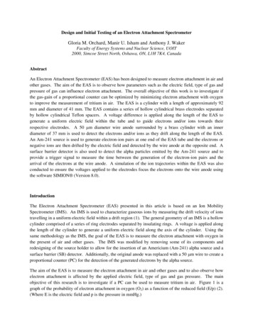
Design and Initial Testing of an Electron Attachment SpectrometerGloria M. Orchard, Manir U. Isham and Anthony J. WakerFaculty of Energy Systems and Nuclear Science, UOIT2000, Simcoe Street North, Oshawa, ON, L1H 7K4, CanadaAbstractAn Electron Attachment Spectrometer (EAS) has been designed to measure electron attachment in air andother gases. The aim of the EAS is to observe how parameters such as the electric field, type of gas andpressure of gas can influence electron attachment. The overall objective of this work is to investigate ifthe gas-gain of a proportional counter can be optimized by minimizing electron attachment with oxygento improve the measurement of tritium in air. The EAS is a cylinder with a length of approximately 92mm and diameter of 41 mm. The EAS contains a series of hollow cylindrical brass electrodes separatedby hollow cylindrical Teflon spacers. A voltage difference is applied along the length of the EAS togenerate a uniform electric field within the tube and to guide electrons and/or ions towards theirrespective electrodes. A 50 m diameter wire anode surrounded by a brass cylinder with an innerdiameter of 37 mm is used to detect the electrons and/or ions as they drift along the length of the EAS.An Am-241 source is used to generate electron-ion pairs at one end of the EAS tube and the electrons ornegative ions are then drifted by the electric field and detected by the wire anode at the opposite end. Asurface barrier detector is also used to detect the alpha particles emitted by the Am-241 source and toprovide a trigger signal to measure the time between the generation of the electron-ion pairs and thearrival of the electrons at the wire anode. A simulation of the ion trajectories within the EAS was alsoconducted to ensure the voltages applied to the electrodes focus the electrons onto the wire anode usingthe software SIMION (Version 8.0).IntroductionThe Electron Attachment Spectrometer (EAS) presented in this article is based on an Ion MobilitySpectrometer (IMS). An IMS is used to characterize gaseous ions by measuring the drift velocity of ionstravelling in a uniform electric field within a drift region (1). The general geometry of an IMS is a hollowcylinder comprised of a series of ring electrodes separated by insulating rings. A voltage is applied alongthe length of the cylinder to generate a uniform electric field along the axis of the cylinder. Using thesame methodology as the IMS, the goal of the EAS is to measure the electron attachment with oxygen inthe present of air and other gases. The IMS was modified by removing some of its components andredesigning of the source holder to allow for the insertion of an Americium (Am-241) alpha source and asurface barrier (SB) detector. Additionally, the original anode was replaced with a 50 m wire to create aproportional counter (PC) for the detection of the generated electrons by the alpha source.The aim of the EAS is to measure the electron attachment in air and other gases and to also observe howelectron attachment is affected by the applied electric field, type of gas and gas pressure. The mainobjective of this research is to investigate if a PC can be used to measure tritium in air. Figure 1 is agraph of the probability of electron attachment in oxygen (O2) as a function of the reduced field (E/p) (2).(Where E is the electric field and p is the pressure in mmHg.)
Figure 1: Probability of electron attachment in oxygen (O2) and water (H2O) as a function of reducedfield (E/p).From the graph, a minimum of electron attachment in O2 occurs between 0 and 2 V/cm/mmHg. Givenour interest in minimizing electron attachment at atmospheric pressure (760 mmHg) an electric fieldalong the drift tube of 200 V/cm is within this range. In the work presented here the design of the EAS isdescribed along with the generation of ions using an Am-241 source. Additionally, a simulation of theEAS using the SIMION software is presented.Experimental Design and SetupDetector DesignThe EAS is composed of cylindrical brass and Teflon pieces creating a hollow cylinder with a total lengthof 92 mm and an outer diameter of 41 mm. Figure 2 is a cross-section of the EAS along the diameter ofthe detector. The detector can be broken down into three sections: (i) source holder/ionization region, (ii)drift region and (iii) collection region. The source holder is designed to insert an Americium-241 (Am241) alpha source and a surface barrier (SB) detector across from each other. The Am-241 source is usedto generate electron-ion pairs within the EAS and the SB is used to detect the alpha particles emitted bythe Am-241 source. Figure 3 is a schematic diagram of the source holder displaying the position of theAm-241 source and SB detector. The drift region is composed of 5 brass rings with inner diameters of 25mm and 37 mm as shown in Figure 2. The thickness of the 25 mm diameter brass rings is 2 mm. TheTeflon spacers between the brass rings also have an inner diameter of 37 mm and a thickness of 1.6 mm.The third region represents a proportional counter (PC) and is composed of 50 m anode wire surroundedby a brass cylinder with an inner diameter of 37 mm. An aperture grid is placed between the last brassring and the anode wire to help guide the ions toward the center of the collection region.
Figure 2: Cross section of EAS. Resistors with values as listed in Table 1 were used to connect the 9electrodes (E).
Figure 3: Cross section of the source holder (SH) shown in Figure 2. The dimensions of SH along withthe Am-241 source and SB detector positions are also illustrated.Electron GenerationFigure 4 is a schematic diagram of the experimental setup used to measure the number of electronsgenerated within the SH by the Am-241 source. The Am-241 source is inserted in the SH as shown inFigure 3 and the components of the EAS are inserted in a steel tube which is then sealed on both ends.This minimizes any external noise. A side port is used to insert the SB detector and align it directlyacross from the Am-241 source. Once the EAS and SB detector are positioned within the steel tubing therequired electronics as shown in Figure 3 were connected.Figure 4: Experimental setup used to test measure the electron-ion pairs generated within the SH. Amulti-channel analyzer (MCA) was used to collect the alpha particles detected by the surface barrier (SB)detected emitted from the Am-241 source.
Electric Field GenerationIn order to collect the generated electrons and negative ions, the ions must be guided towards the anodewire. A uniform electric field along the drift region is generated by using resistors between the brasselectrodes to divide the applied voltage within the drift region of the EAS. Table 1 lists the resistor valuesand corresponding voltages applied to the brass electrodes along the EAS given a HV of -1000V isapplied to the source holder.Table 1: A list of the applied voltage (V) to the nine electrodes (E) corresponding to Figure 1, along withthe resistor values used between the adjacent electrodes (E) to divide the applied high voltage along thenine electrodes of the EAS (i.e. a value of 270 k was used between E2 and E3). *The Outer Cylinder(E9) is connected to ground.EAS Brass ElectrodeSource Holder (E1)Brass Ring (E2)Brass Ring 1 (E3)Brass Ring 2 (E4)Brass Ring 3 (E5)Brass Ring 4 (E6)Brass Ring 5 (E7)Aperture Grid (E8)Outer Cylinder (E9)*Resistor (k )n/a0270270270270270270100Voltage (V)-1000-1000-843-686-529-372-215-580ION Generation and EAS Simulation StudyIon PairsThe Am-241 alpha particles generate ion pairs as they travel through the air. Using the SB detector wewere able to measure the energy of the alpha particles at the SB detector and then calculate the averageenergy loss of the alpha particles and the average number of electron-ion pairs generated within thesource holder. Using the two known alpha particles emitted by a Uranium-238 source (4.196 MeV and4.7758 MeV) the SB detector was calibrated with energy. The energy of the alpha particles emitted bythe Am-241 source is 5.465 MeV. By measuring the energy of the emitted particles at the SB detector asa function of distance from the source, the energy loss in air within the source holder was obtained.Figure 5 displays the alpha energy loss measured with the SB detector as a function of distance from thesource.
Alpha Energy Loss In Air (MeV)6y -2E-05x3 0.003x2 0.0258x 0.0059R² 0.99954321001020304050Source to Detector Distance (mm)Figure 5: Am-241 alpha energy loss in air as a function of distance from the source. The surface barrier(SB) detector was place directly across from the source at various distances from the source to measurethe energy.Using the measured energy loss of the Am-241 alpha particles and the NIST data for the range of alphaparticles in air, the average number of electron-ion pairs generated within the ionization region of thesource holder per alpha particle emitted is 31 000 which corresponds to an energy loss of 1.088 MeV.Figure 6 is a graph of the Am-241 alpha peak as detected by the SB when aligned within the sourceholder as shown in the experimental setup in Figure 4. Given approximately 31 000 electron-ion pairs aregenerated within the ionization region of the source holder per alpha particle and if there is no electronattachment than we expect all 31 000 electrons to be guided through the drift tube of the EAS andcollected by the anode wire.Figure 6: Spectrum obtained using the MCA and the configuration of the Am-241 source and SBdetector as shown in Figure 3.
SIMION SimulationIn order to verify the electric field within the EAS and to ensure the electrons (and/or negative ions) aredirected toward the anode wire a simulation using SIMION was conducted. The SIMION softwareallows for the input of the detector geometry and to apply the desired voltages to the electrodes. Inaddition to the voltages of the nine electrodes listed in Table 1, a voltage of 1000 V was also applied tothe anode wire for the simulation. Figure 7 is a snapshot of the simulation after flying 100 electronsthrough the EAS. From the simulation an electric field of 200 V/cm is calculated along the axis of thecylinder. This electric field value is ideal for electron drift within the drift tube of the EAS (1) andminimal electron attachment in O2 (2).Figure 7: SIMION simulation of the EAS detector in vacuum. The blue represents 100 electrontrajectories originating at the source holder (left in figure) and ending at the anode wire. The voltageslisted in Table 1 were applied to the electrodes and 1000 V was applied to the anode wire.Future WorkGiven the initial simulation has provided positive results on the trajectories of the electrons towards theanode wire, the next steps include additional simulations using SIMION and experiments using theEAS. Using the SIMION software a simulation of the EAS in an air environment instead of vacuumwill provide information on how the electron trajectories may be affected due to the presence of air withinthe EAS cavity. In terms of experimental studies, the first step is to connect the anode wire to a HVsource and preamplifier and observe if a signal coming from the generated electrons by the Am-241source can be detected. Once these studies are completed additional experiments using the EAS can beconducted to assess the sensitivity of the system on electron attachment.
AcknowledgementsThe authors would like to thank NSERC for providing PDF funding to G.M Orchard.References1. Eiceman, Gary A. Ion Mobility Spectrometry. s.l. : CRC Press, LLC, 2005.2. Rossi, Bruno B and Staub, Hans H. Ionization Chambers and Counters. New York : McGraw-HillBook Company, INC., 1949.
The thickness of the 25 mm diameter brass rings is 2 mm. The Teflon spacers between the brass rings also have an inner diameter of 37 mm and a thickness of 1.6 mm. The third region represents a proportional counter (PC) and is composed of 50 m anode wire surrounded by a brass cylinder with an inner diameter of 37 mm.