Transcription
Solution GuideOpen Compute NetworkOperating System Version 1.21OcNOS Validated Solution GuideEBGP-based Data Center with OcNOSipinfusion
Solution GuideContentsCHAPTER 1 . . . . . . . . . . . . . . . . . . . . . . . . . . . . . . . . . . . . . . . . . . . . . . . . . . . . . . . . . . . . . . . . . . . . . . . . . . . . 4Data Center Interconnect Overview . . . . . . . . . . . . . . . . . . . . . . . . . . . . . . . . . . . . . . . . . . . . . . . . . . . . . . . . 4Large-Scale Data Center Requirements . . . . . . . . . . . . . . . . . . . . . . . . . . . . . . . . . . . . . . . . . . . . . . . . . 4Large-Scale Data Center Topologies . . . . . . . . . . . . . . . . . . . . . . . . . . . . . . . . . . . . . . . . . . . . . . . . . . . . 4Large-Scale Data Center Routing . . . . . . . . . . . . . . . . . . . . . . . . . . . . . . . . . . . . . . . . . . . . . . . . . . . . . . 4EBGP-Routed Clos Topology-Based Data Center . . . . . . . . . . . . . . . . . . . . . . . . . . . . . . . . . . . . . . . . . 4EBGP Data Center Design using OcNOS . . . . . . . . . . . . . . . . . . . . . . . . . . . . . . . . . . . . . . . . . . . . . . . . 5CHAPTER 2 . . . . . . . . . . . . . . . . . . . . . . . . . . . . . . . . . . . . . . . . . . . . . . . . . . . . . . . . . . . . . . . . . . . . . . . . . . . . 8Configuration . . . . . . . . . . . . . . . . . . . . . . . . . . . . . . . . . . . . . . . . . . . . . . . . . . . . . . . . . . . . . . . . . . . . . . . . . . 8ToR (leaf node) . . . . . . . . . . . . . . . . . . . . . . . . . . . . . . . . . . . . . . . . . . . . . . . . . . . . . . . . . . . . . . . . . . . . . 8Tier-2 (spine node) . . . . . . . . . . . . . . . . . . . . . . . . . . . . . . . . . . . . . . . . . . . . . . . . . . . . . . . . . . . . . . . . . . 8Tier-3 (core node) . . . . . . . . . . . . . . . . . . . . . . . . . . . . . . . . . . . . . . . . . . . . . . . . . . . . . . . . . . . . . . . . . . 10Tier-2 (border router) . . . . . . . . . . . . . . . . . . . . . . . . . . . . . . . . . . . . . . . . . . . . . . . . . . . . . . . . . . . . . . . . 11Tier-3 (WAN router) . . . . . . . . . . . . . . . . . . . . . . . . . . . . . . . . . . . . . . . . . . . . . . . . . . . . . . . . . . . . . . . . 12Other Configurations . . . . . . . . . . . . . . . . . . . . . . . . . . . . . . . . . . . . . . . . . . . . . . . . . . . . . . . . . . . . . . . 12Validation . . . . . . . . . . . . . . . . . . . . . . . . . . . . . . . . . . . . . . . . . . . . . . . . . . . . . . . . . . . . . . . . . . . . . . . . . . . . . . 13Conclusion . . . . . . . . . . . . . . . . . . . . . . . . . . . . . . . . . . . . . . . . . . . . . . . . . . . . . . . . . . . . . . . . . . . . . . . . . . . . 15References . . . . . . . . . . . . . . . . . . . . . . . . . . . . . . . . . . . . . . . . . . . . . . . . . . . . . . . . . . . . . . . . . . . . . . . . . . . . 15Appendix A: Configuring the Data Center through NetConf . . . . . . . . . . . . . . . . . . . . . . . . . . . . . . . . . . . . . . 16Appendix B: NetConf User Guide . . . . . . . . . . . . . . . . . . . . . . . . . . . . . . . . . . . . . . . . . . . . . . . . . . . . . . . . . . . 222
Solution GuideGlossaryBGPBorder Gateway Routing ProtocolEBGPExternal BGPSTPSpanning Tree ProtocolTRILLTransparent Interconnection of Lots of LinksSPBShortest Path BridgingECMPEqual Cost Multipath3
Solution GuideChapter 1Data Center OverviewNetwork Automation provides IT administrators and network operators significant benefits. This solution guidedescribes an approach to build data centers using Layer3 BGP routing protocol.It also summarizes on some design philosophies for data center and why E-BGP is better suited. Large-scale data center requirements Large-scale data center topologies Large-scale data center routing EBGP-routed large-scale Clos topology-based data centerLarge-Scale Data Center RequirementsThe design of large-scale data centers is driven by operational simplicity and network stability. Operationalsimplicity and network stability ensures easier manageability and therefore reduced operational expenses.From the network design aspect, the requirements are: Ability to accommodate the variable-application bandwidth and strict latency requirements. Ability to handle the increased east-west (server-to-server) traffic within the data center due to massivedata replication between clusters and virtual machine migrations. Traffic-Engineering with application load balancing. The network infrastructure should itself performcontrolled per-hop traffic engineering. Minimize CAPEX and incorporate vendor diversity by using a simple, interoperable routing protocol with aminimal set of features. A design to minimize OPEX by keeping the failure domain at the lowest level in the network hierarchy.Large-Scale Data Center TopologiesA traditional tree-based (upside down) topology with a three-layer hierarchy of core, aggregation and accesslayer can be used in a data center design. This approach is suited if the majority of the traffic is enteringand leaving (north-south) the data center. An increase in bandwidth requirements then can be addressed byupgrading the device line cards or port density. However with the current trend of increasing server-to-server(east-west) traffic, scaling these networks horizontally is expensive or impossible at times.A Clos network (leaf and spine) is a horizontally scalable topology where every leaf node is connected toevery other spine. The topology can be extended to different stages for scaling. Clos networks are fully nonblocking and load balancing is inherent in the topology itself as all available paths are ECMP. Clos networksare ideal for the current requirements of a large-scale data center.Large-Scale Data Center RoutingLayer 2-only routing was used in a traditional tree-based data center topology. Traditional layer-2 protocolssuch as STP do not give bi-sectional bandwidth, whereas recent developments such as TRILL, SPB haveselected vendor support.However, a hybrid of layer 2 /layer 3 can be used to limit the size of failure domain and scale up the datacenter. Layer 3 routing can be used in tier 1 (core) and layer 2 in tier 3 (access). Tier 2 can be based on eitherlayer 2 or layer 3. A hybrid model has the advantage of seamless Virtual Machine mobility and requires lessIP subnets for the data center. Although this design can scale-up, it is difficult and complex to manage thedifferent protocols.4
Solution GuideA layer 3 only design simplifies the network and improves network stability and scalability, as well aslocalizing the failure domain (confined to the L2 broadcast domain). Seamless virtual mobility can be achievedin a L3 only based data center by using L2 overlay networks. From experiment and analysis, External BGP(EBGP) is considered ideal compared to IGPs due to the following [See Reference]: Less complex protocol, simple state machine Information flooding overhead is less, no frequent updates unlike IGPs Network failure recovery is very fast. Although BGP convergence is slower than IGP, in a Clos topologywith ECMP links, the failure is masked as soon as an alternate path is found. Failure domain is minimized in a Clos topology with EBGP. Some of the failures are local/hidden/notpropagated if the failed link was not selected/advertised as the best path among the ECMP paths by theBGP speaker. The failures, where all devices have to withdraw some prefixes or update the ECMP groupsin the FIB, are very limited and in those failures the failed link/node does not impact the re-convergenceprocess. Administrator can define the application traffic path. BGP provides services like prefix distribution, prefixfiltering, traffic engineering, traffic tagging, and multi-vendor stability better than other IGPs. Easier to troubleshoot.EBGP-Routed CLOS Topology-Based Data CenterEBGP-routed CLOS topology is considered the best choice for laying the IP fabric in a data center becauseof the horizontal scalability feature of Clos topology and the ease of use and services provided by EBGPespecially prefix-filtering, prefix distribution, and traffic engineering which are required extensively in adata center.Configuration GuidelinesConfiguration guidelines for laying IP fabric using EBGP efficiently are as follows: Run all EBGP sessions over single-hop point-to-point links. Use private Autonomous System Numbers (ASNs) (64512-65534) to avoid ASN conflicts. Give all tier 1 (core) devices a single ASN. Give all tier 2 devices in the same cluster the same unique ASN. A cluster or pod is a group of tier 2 (spineswitches) tier 3 switches (ToR/leaf) servers. Give every tier 3 (ToR) device in a cluster a unique ASN. Reuse tier-3 ASNs across clusters. Configure tier-3 devices with the BGP “allowas-in” feature to allow routelearning of prefixes from the same ASNs in other clusters. Announce server subnets on tier-3 devices via BGP without using route summarization on tier-2 and tier-1devices. Use edge clusters (pods) for external connectivity. Each edge cluster consists of border routers (tier-2) and WANrouters (tier-3). Give each WAN router a unique public ASN to connect the data center to the external world. For border routers, remove private ASNs before sending the information to WAN routers by configuringborder routers with the “remove-private-AS” BGP feature. To relax the BGP ECMP criteria for AS paths, configure BGP “as-path multipath-relax” on all routers/switches. This way, an equal cost path with a different AS PATH, but the same AS PATH length is alsoconsidered an equal cost path (ECMP).5
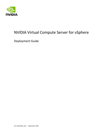
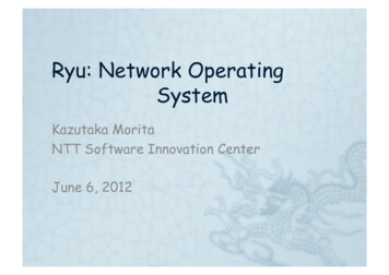
Solution Guide For faster failure detection, configure the BGP session with BFD. To avoid recurring BPG update/selection for a single failure through all peers or BGP update messagedispersion on a particular speaker, use BGP update groups. The BGP update group feature processes anupdate once and sends it to a group of neighbors that share a common outbound policy. The BGP RIB isscanned every time for each peer to apply the outbound filter. To avoid micro routing loops, configure tier-2 and tier-1 with static discard or null routes rather than a defaultroute. Routing loops can happen when a tier-2 device has lost all its learned prefixes, but has a defaultroute to a tier-1 device and that tier-1 device still has a route back to the tier-2 device.EBGP Data Center Design using OcNOSFigure-1 shows a minimal representation that encompasses all the elements in a layer 3 data center.The number of ECMPs in the data center is equal to the number of cores (tier-1 switches).Figure 1. IP fabric using EBGPCore Tier 1Border RouterExternal Cluster/PodSpine Tier 2Tier 3TOR 1TOR 2TOR 3TOR 1TOR 2TOR 3WAN RoutersCluster/PodInternet6
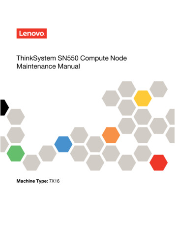
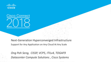
Solution GuideFigure 2 shows the Autonomous System Number (ASN) allocation scheme used in the data center. The WANrouters are assigned a public ASN, which connects the data center to external world. The tier-3 ASNs perToR are reused across the clusters.Figure 2: ASN allocation in an EBGP-based data centerASN 65534R11R12R14ASV 64603External ClusterTOR 1TOR 2TOR 3TOR 1TOR 2TOR 3ASN 65501ASN 65502ASN 65500ASN 65501ASN 65502ASN 64602ASN 65500ASN 64601R13Cluster 1Cluster 27ASN 100InternetASN 101
Solution GuideChapter 2ConfigurationToR (Leaf node)CommandPurposeStep 1(config)#interface xe1Enter interface mode.Step 2(config-if)#ip address 32.1.0.3/24Configure ip address on the InterfaceStep 3(config-if)#exitExit interface mode.Step 4(config)#interface xe2Enter interface mode.Step 5(config-if)#exitExit interface mode.Step 6(config)#router bgp 65500Configure the EBGP routing process with private ASNStep 7(config-router)#max-paths ebgp 8Exit interface mode.Step 8(config-router)#neighbor 32.1.0.2remote-as 64601Configure maximum EBGP ECMP that can be installed inBGP.Step 9(config-router)#neighbor 32.1.0.2fall-over bfdConfigure the EBGP neighbor over the connectedinterface using the neighbor IP and remote private ASNStep 10(config-router)#neighbor 32.1.0.2allowas-inConfigure BFD for the BGP session for faster failuredetection.Step 11(config-router)#neighbor 32.2.0.2remote-as 64601Configure “allowas-in” for the neighbor to accept routeswith same ASN learned over this neighborStep 12(config-router)#neighbor 32.2.0.2fall-over bfdConfigure the EBGP neighbor over the connectedinterface using the neighbor IP and remote private ASNStep 13(config-router)#neighbor 32.2.0.2allowas-inConfigure BFD for the BGP session for faster failuredetection.Step 14(config-router)#exitConfigure “allowas-in” for the neighbor to accept routeswith same ASN learned over this neighborStep 15(config-router)#exitExit Router mode.Tier-2 (Spine node)CommandPurposeConfigure the interfacesStep 1(config)#interface xe1Enter interface mode.Step 2(config-if)#ip address 32.1.0.2/24Configure ip address on the interfaceStep 3(config-if)#exitExit interface mode.Step 4(config)#interface xe46Enter interface mode.Step 5(config-if)#ip address 32.3.0.2/24Configure an IP address on the interfaceStep 6(config)#interface xe47Enter interface mode.Step 7(config-if)#ip address 32.4.0.2/24Configure an IP address on the interfaceStep 8(config)#interface xe48Enter interface mode.Step 9(config-if)#ip address 21.1.0.2/24Configure an IP address on the interfaceStep 10(config)#interface xe46Enter interface mode.Step 11(config-if)#ip address 21.2.0.2/24Configure an IP address on the interfaceStep 12(config)#router bgp 64601Configure the eBGP routing process with private ASN8
Solution GuideTier-2 (Spine node) cont.CommandPurposeConfigure BGP on the routerStep 13(config-router)#bgp bestpath as-pathmultipath-relaxConfigure “as-path multipath-relax” to relax the AS-PATHexact match (if AS-PATH length are same) criteria for BGPECMPStep 14(config-router)#max-paths ebgp 8Configure maximum EBGP ECMP that can be installedin BGP.Step 15(config-router)#neighbor 32.1.0.3remote-as 65000Configure the EBGP neighbor over the connectedinterface using the neighbor IP and remote ASNStep 16(config-router)#neighbor 32.1.0.3fall-over bfdConfigure BFD for the BGP session for faster failuredetection.Step 17(config-router)#neighbor 32.3.0.3remote-as 65001Configure the EBGP neighbor over the connectedinterface using the neighbor IP and remote ASNStep 18(config-router)#neighbor 32.3.0.3fall-over bfdConfigure BFD for the BGP session for faster failuredetection.Step 19(config-router)#neighbor 32.4.0.3remote-as 65002Configure the EBGP neighbor over the connectedinterface using the neighbor IP and remote ASNStep 20(config-router)#neighbor 32.1.0.3fall-over bfdConfigure BFD for the BGP session for faster failuredetection.Step 21(config-router)#neighbor 21.1.0.1remote-as 65534Configure the EBGP neighbor over the connectedinterface using the neighbor IP and remote ASNStep 22(config-router)#neighbor 21.1.0.1fall-over bfdConfigure BFD for the BGP session for faster failuredetection.Step 23(config-router)#neighbor 21.2.0.1remote-as 65534Configure the EBGP neighbor over the connectedinterface using the neighbor IP and remote ASNStep 24(config-router)#neighbor 21.2.0.1fall-over bfdConfigure BFD for the BGP session for faster failuredetection.Step 25(config-router)#exitExit Router mode.9
Solution GuideTier-3 (Core node)CommandPurposeConfigure the interfacesStep 1(config)#interface xe1Enter interface mode.Step 2(config-if)#ip address 21.1.0.1/24Configure ip address on the interfaceStep 3(config-if)#exitExit interface mode.Step 4(config)#interface xe46Enter interface mode.Step 5(config-if)#ip address 21.5.0.1/24Configure an IP address on the interfaceStep 6(config)#interface xe49Enter interface mode.Step 7(config-if)#ip address 41.1.0.1/24Configure an IP address on the interfaceStep 8(config)#interface xe50Enter interface mode.Step 9(config-if)#ip address 41.5.0.1/24Configure an IP address on the interfaceConfigure BGP on the routerStep 10(config)#router bgp 65534Configure the eBGP routing process with private ASNStep 11(config-router)#bgp bestpathas-path multipath-relaxConfigure “as-path multipath-relax” to relax the AS-PATHexact match (if AS-PATH length are same) criteria forBGP ECMPStep 12(config-router)#max-paths ebgp 8Configure maximum EBGP ECMP that can be installedin BGP.Step 13(config-router)#neighbor 21.1.0.2remote-as 64601Configure the EBGP neighbor over the connectedinterface using the neighbor IP and remote ASNStep 14(config-router)#neighbor 21.1.0.2fall-over bfdConfigure BFD for the BGP session for faster failuredetection.Step 15(config-router)#neighbor 21.5.0.3remote-as 64602Configure the EBGP neighbor over the connectedinterface using the neighbor IP and remote ASNStep 16(config-router)#neighbor 21.5.0.3fall-over bfdConfigure BFD for the BGP session for faster failuredetection.Step 17(config-router)#neighbor 41.1.0.3remote-as 64603Configure the EBGP neighbor over the connectedinterface using the neighbor IP and remote ASNStep 18(config-router)#neighbor 41.1.0.3fall-over bfdConfigure BFD for the BGP session for faster failuredetection.Step 19(config-router)#neighbor 41.5.0.3remote-as 64603Configure the EBGP neighbor over the connectedinterface using the neighbor IP and remote ASNStep 20(config-router)#neighbor 41.5.0.3fall-over bfdConfigure BFD for the BGP session for faster failuredetection.Step 21(config-router)#exitExit BGP mode10
Solution GuideTier 2 (Border router)CommandPurposeConfigure the interfacesStep 1(config)#interface xe1Enter interface mode.Step 2(config-if)#ip address 41.1.0.2/24Configure an IP address on the interfaceStep 3(config-if)#exitExit interface mode.Step 4(config)#interface xe46Enter interface mode.Step 5(config-if)#ip address 41.2.0.2/24Configure an IP address on the interfaceStep 6(config)#interface xe47Enter interface mode.Step 7(config-if)#ip address 41.3.0.2/24Configure an IP address on the interfaceStep 8(config)#interface xe48Enter interface mode.Step 9(config-if)#ip address 41.4.0.2/24Configure an IP address on the interfaceStep 10(config)#interface xe49Enter interface mode.Step 11(config-if)#ip address 51.1.0.2/24Configure an IP address on the interfaceStep 12(config)#interface xe50Enter interface mode.Step 13(config-if)#ip address 51.3.0.2/24Configure an IP address on the interfaceStep 14(config)#router bgp 64603Configure the eBGP routing process with private ASNStep 15(config-router)#bgp bestpathas-path multipath-relaxConfigure “as-path multipath-relax” to relax the AS-PATHexact match (if AS-PATH length are same) criteria forBGP ECMPStep 16(config-router)#max-paths ebgp 8Configure maximum EBGP ECMP that can be installed in BGP.Step 17(config-router)#neighbor 41.1.0.1remote-as 65534Configure the EBGP neighbor over the connected interfaceusing the neighbor IP and remote ASNStep 18(config-router)#neighbor 41.1.0.1fall-over bfdConfigure BFD for the BGP session for faster failuredetection.Step 19(config-router)#neighbor 41.2.0.1remote-as 65534Configure the EBGP neighbor over the connectedinterface using the neighbor IP and remote ASNStep 20(config-router)#neighbor 41.2.0.1fall-over bfdConfigure BFD for the BGP session for faster failuredetection.Step 21(config-router)#neighbor 41.3.0.1remote-as 65534Configure the EBGP neighbor over the connectedinterface using the neighbor IP and remote ASNStep 22(config-router)#neighbor 41.3.0.1fall-over bfdConfigure BFD for the BGP session for faster failuredetection.Step 23(config-router)#neighbor 41.4.0.1remote-as 65534Configure the EBGP neighbor over the connectedinterface using the neighbor IP and remote ASNStep 24(config-router)#neighbor 41.4.0.1fall-over bfdConfigure BFD for the BGP session for faster failuredetection.Step 25(config-router)#neighbor 51.1.0.3remote-as 100Configure the EBGP neighbor over the connectedinterface using the neighbor IP and remote ASNConfigure BGP on the routerStep 26(config-router)#neighbor 51.1.0.3fall-over bfdConfigure BFD for the BGP session for faster failuredetection.Step 27(config-router)#neighbor 51.1.0.3remove-private-ASConfigure “remove –private-AS” to remove the private ASNsfor the routes advertised to this neighbor.Step 28(config-router)#neighbor 51.3.0.3remote-as 101Configure the EBGP neighbor over the connectedinterface using the neighbor IP and remote ASN11
Solution GuideTier 2 (Border router) Cont.CommandPurposeConfigure BGP on the routerStep 29(config-router)#neighbor 51.3.0.3fall-over bfdConfigure BFD for the BGP session for faster failuredetection.Step 30(config-router)#neighbor 51.3.0.3remove-private-ASConfigure “remove –private-AS” to remove the private ASNsfor the routes advertised to this neighbor.Step 31(config-router)#exitExit BGP modeTier-3 (WAN router)This is a partial list and does not contain the Internet configuration.CommandPurposeConfigure the interfacesStep 1(config)#interface xe1Enter interface mode.Step 2(config-if)#ip address 51.1.0.3/24Configure an IP address on the interfaceStep 3(config-if)#exitExit interface mode.Step 4(config)#interface xe46Enter interface mode.Step 5(config-if)#ip address 51.2.0.3/24Configure an IP address on the interfaceConfigure BGP on the routerStep 6(config)#router bgp 100Configure the eBGP routing process with public ASNStep 7(config-router)#max-paths ebgp 8Configure maximum EBGP ECMP that can be installed inBGP.Step 8(config-router)#neighbor 51.1.0.2remote-as 64603Configure the EBGP neighbor over the connectedinterface using the neighbor IP and remote ASNStep 9(config-router)#neighbor 51.1.0.2fall-over bfdConfigure BFD for the BGP session for faster failuredetection.Step 10(config-router)#neighbor 51.3.0.2remote-as 64603Configure the EBGP neighbor over the connectedinterface using the neighbor IP and remote ASNStep 11(config-router)#neighbor 51.3.0.2fall-over bfdConfigure BFD for the BGP session for faster failuredetection.Step 12(config-router)#exitExit BGP modeOther ConfigurationsYou must repeat similar configurations for all ToR, spine, core, border, and WAN devices as well.12
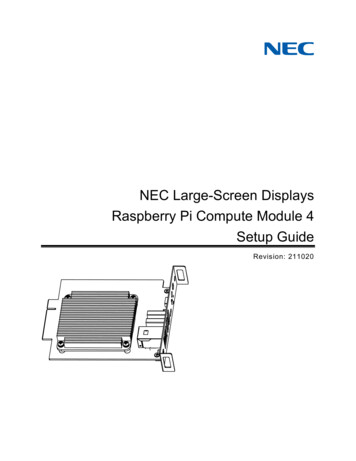
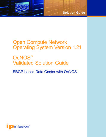
Solution GuideValidationUse the show ip bgp command to validate the output at each node.Consider the following case: for application load balancing and high availability/reliability, two similarapplication servers can be placed at two clusters. For users accessing the application server through theInternet, the access to the server is load balanced and failure of one of the application servers does notimpact the accessibility. The following is the output at various nodes for a subnet, such as: 70.70.70.1 (application server) at ToR1 in cluster 1 and cluster 2 80.80.80.1 at ToR 1 cluster 1 90.90.90.1 at ToR 1 cluster 2ToR 1 Cluster 1ToR 1 Cluster 213
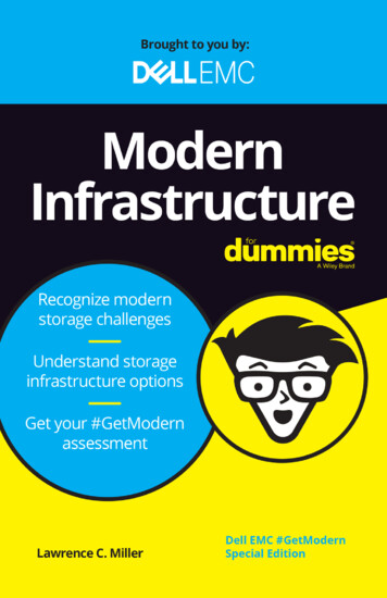
Solution GuideR1 Cluster 1R11 Tier 1Border Router B1 Tier 2 External Cluster14
Solution GuideWAN Router WR1 External ClusterConclusionOcNOS with EBGP routing is a highly scalable, simple and flexible way of laying IP fabric in a data center.The data center can be easily scaled for: Higher computing needs by adding more clusters. Higher performance and redundancy by adding more cores Higher uplink speeds by adding more external/edge clusters.ReferencesUse of BGP for routing in large scale data wg-bgp-routing-large-dc-0915
Solution GuideAppendix A: Configuring the DataCenter through NetConfThis appendix shows how to configure a data center through NetConf. This section contains XML payloadswhich can be used by any NetConf client to send configurations to OcNOS devices.The configurations below in XML are communicated via RPC messages from the NetConf client to theNetConf server.This document uses the yang-cli which is part of open source OpenYumaMaster which and is preinstalled ona ZebM-enabled OcNOS ONIE package as a NetConf client.Pre-requisiteRefer to Yangcli Operations section of the NetConf User Guide and perform these operations first:1. Establish Connection2. Load ModulesOnce the above operations are complete, edit-config operation can be performed with XML payloads usingthe command:yangcli ocnos@Hostname edit-config config @/ path-to-xml-file / xml-file .xmlSave the below xml payloads as an .xml file in any desired location. Make sure that each XML payload startswith vr xmlns ” namespace ” and ends with /vr .TOR (leaf node)TOR.xmlThis table shows the XML to configure an IP address:XML PayloadDescription vr xmlns ”http://www.ipinfusion.com/CMLSchema/ZebOS” namespace of the ZebOS module vrId 0 /vrId Vrid interface ifName xe49 /ifName ipAddr 50.52.1.1/24 /ipAddr /interface interface ifName ge2 /ifName ipAddr 50.54.1.1/24 /ipAddr /interface Configure the interfaces which are connected to theSPINE routers.This payload configures the IP address of theinterfaces xe49 and ge2. /vr Close namespace for the ZebOS module16
Solution GuideThis is an example of the XML payload to be sourced in the yang CLI to configure an interface IP addresses: vr xmlns ”http://www.ipinfusion.com/CMLSchema/ZebOS” vrId 0 /vrId interface ifName xe49 /ifName ipAddr 50.52.1.1/24 /ipAddr /interface interface ifName ge2 /ifName ipAddr 50.54.1.1/24 /ipAddr /interface /vr This table shows the XML to configure BGP attributes:XML PayloadDescription vr xmlns ”http://www.ipinfusion.com/CMLSchema/ZebOS” Namespace of the ZebOS module vrId 0 /vrId Enter Vrid bgp Open BGP tag.Configure the BGP AS number. bgpAs 64602 /bgpAs multipathRelax 1 /multipathRelax vrfName default /vrfName Configure “as-path multipath-relax” to relax theAS-PATH criteria for BGP ECMP multipath bgpType ebgp /bgpType multipathType multipathsNum 8 / multipathsNum /multipathType /multipath Configure maximum EBGP ECMP that can beinstalled in BGP. bgpPeer peerAddr 50.52.1.2 /peerAddr allowAsNum 3 /allowAsNum bgpPeerBfd 1 /bgpPeerBfd peerAs 64902 /peerAs /bgpPeer Configure BGP peer with AS 64902 and peeraddress 50.52.1.2Enable BFD for link failure detectionConfigure “allowas” in for the neighbor toaccept routes with same ASN learned over thisneighbor bgpPeer peerAddr 50.54.1.2 /peerAddr allowAsNum 3 /allowAsNum bgpPeerBfd 1 /bgpPeerBfd peerAs 64902 /peerAs /bgpPeer Configure BGP peer with AS 64902 and peeraddress 50.54.1.2Configure “allowas” in for the neighbor to acceptroutes with same ASN learned over this neighborEnable BFD for link failure detection. bgpRedistList redistType connected /redistType /bgpRedistList bgpRedistList redistType ospf /redistType /bgpRedistList Redistribute the connected and OSPF routes /bgp Close BGP tag. /vr Close namespace for the ZebOS module17
Solution GuideTier-2 (spine node)SPINE.xmlThis table shows the XML to configure IP addresses:XML PayloadDescription vr xmlns ”http://www.ipinfusion.com/CMLSchema/ZebOS” Enter namespace of the ZebOS module vrId 0 /vrId Enter Vrid interface ifName xe49/1 /ifName ipAddr 50.52.1.2/24 /ipAddr /interface interface ifName xe49/2 /ifName ipAddr 52.31.1.1/24 /ipAddr /interface Configure the interfaces which are connectedto the SPINE routers.This payload configures the IP address of theinterfaces xe49/1 and xe49/2. /vr Close namespace for the ZebOS moduleThis table shows the XML to configure BGP attributes:XML PayloadDescription vr xmlns ”http://www.ipinfusion.com/CMLSchema/ZebOS” Enter namespace of the ZebOS module vrId 0 /vrId Enter Vrid bgp Open BGP tag.Configure the BGP AS number. bgpAs 64902 /bgpAs multipathRelax 1 /multipathRelax vrfName default /vrfName Configure “as-path multipath-relax” to relax theAS-PATH criteria for BGP ECMP multipath bgpType ebgp /bgpType multipathType multipathsNum 8 /multipathsNum /multipathType /multipath Configure maximum EBGP ECMP that can beinstalled in BGP. bgpRedistList redistType connected /redistType /bgpRedistList Redistribute the connected routes bgpPeer peerAddr 52.31.1.2 /peerAddr bgpPeerBfd 1 /bgpPeerBfd peerAs 65501 /peerAs /bgpPeer Configure BGP peer with AS 65501 and peeraddress 52.31.1.2Enable BFD for link failure detection. bgpPeer peerAddr 50.52.1.1 /peerAddr bgpPeerBfd 1 /bgpPeerBfd peerAs 64601 /peerAs /bgpPeer Configure BGP peer with AS 64602 and peeraddress 50.52.1.1Enable BFD for link failure detection. /bgp Close BGP tag. /vr Close namespace for the ZebOS module18
Solution GuideTier-3 (core node)CORE.xmlThis table shows the XML to configure IP addresses:XML PayloadDescription vr xmlns ”http://www.ipinfusion.com/CMLSchema/ZebOS” Enter namespace of the ZebOS module vrId 0 /vrId Enter Vrid interface ifName xe1 /ifName linkStatus 1 /linkStatus ipLabel NULL /ipLabel ipAddr 52.31.1.2/24 /ipAddr /interface interface ifName ge8 /ifName linkStatus 0 /linkStatus ipLabel NULL /ipLabel ipAddr 31.22.1.1/24 /ipAddr /interface Configure the interfaces that are connected tothe spine routers.This payload configures the IP address of theinterfaces xe1 and ge8. /vr Close namespace for the ZebOS moduleThis table shows the XML to configure BGP attributes:XML PayloadDescription vr xmlns ”http://www.ipinfusion.com/CMLSchema/ZebOS” Enter namespace of the ZebOS module vrId 0 /vrId Enter Vrid bgp Open BGP tag.Configure the BGP AS number. bgpAs 65501 /bgpAs multipathRelax 1 /multipathRelax vrfName default /vrfName Configure “as-path multipath-relax” to relaxthe AS-PATH criteria for BGP ECMP multipath bgpType ebgp /bgpType multipathType multipathsNum 8 /multipathsNum /multipathType /multipath Configure maximum EBGP ECMP that canbe installed in BGP. bgpRedistList redistType connected /redistType /bgpRedistList Redistribute the connected routes bgpPeer peerAddr 31.22.1.2 /peerAddr bgpPeerBfd 1 /bgpPeerBfd peerAs 65503 /peerAs /bgpPeer Configure BGP peer with AS 65503 and peeraddress 31.22.1.2Enable BFD for link failure detection. bgpPeer peerAddr 52.31.1.1 /peerAddr bgpPeerBfd 1 /bgpPeerBfd peerAs 64902 /peerAs /bgpPeer Configure BGP peer with AS 64902 and peeraddress 52.31.1.1Enable BFD for link failure detection. /bgp Close BGP tag. /vr Close namespace for the ZebOS module19
Solution GuideTier-2 (Border Router)This table shows
6 Solution Guide For faster failure detection, configure the BGP session with BFD. To avoid recurring BPG update/selection for a single failure through all peers or BGP update message dispersion on a particular speaker, use BGP update groups. The BGP update group feature processes an update once and sends it to a group of neighbors that share a common outbound policy.