Transcription
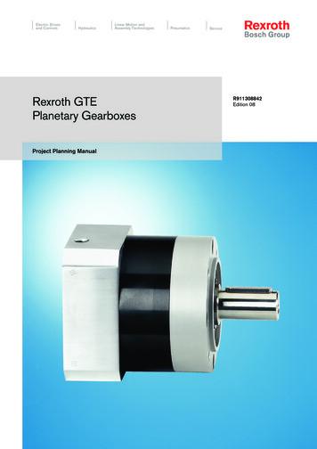
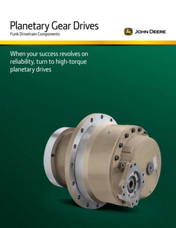
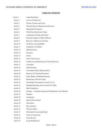
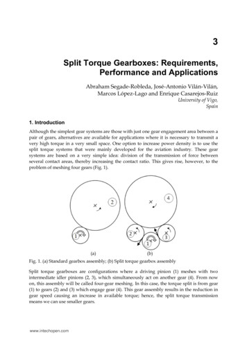
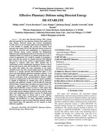
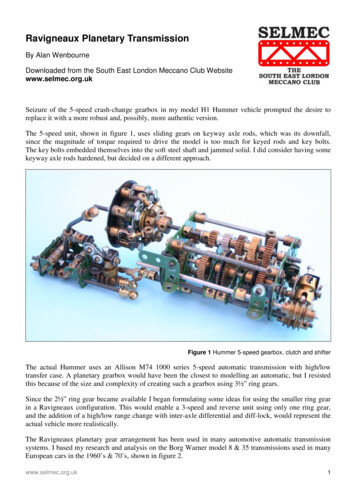
Ravigneaux Planetary TransmissionBy Alan WenbourneDownloaded from the South East London Meccano Club Websitewww.selmec.org.ukSeizure of the 5-speed crash-change gearbox in my model H1 Hummer vehicle prompted the desire toreplace it with a more robust and, possibly, more authentic version.The 5-speed unit, shown in figure 1, uses sliding gears on keyway axle rods, which was its downfall,since the magnitude of torque required to drive the model is too much for keyed rods and key bolts.The key bolts embedded themselves into the soft steel shaft and jammed solid. I did consider having somekeyway axle rods hardened, but decided on a different approach.Figure 1 Hummer 5-speed gearbox, clutch and shifterThe actual Hummer uses an Allison M74 1000 series 5-speed automatic transmission with high/lowtransfer case. A planetary gearbox would have been the closest to modelling an automatic, but I resistedthis because of the size and complexity of creating such a gearbox using 3½” ring gears.Since the 2½” ring gear became available I began formulating some ideas for using the smaller ring gearin a Ravigneaux configuration. This would enable a 3-speed and reverse unit using only one ring gear,and the addition of a high/low range change with inter-axle differential and diff-lock, would represent theactual vehicle more realistically.The Ravigneaux planetary gear arrangement has been used in many automotive automatic transmissionsystems. I based my research and analysis on the Borg Warner model 8 & 35 transmissions used in manyEuropean cars in the 1960’s & 70’s, shown in figure 2.www.selmec.org.uk1
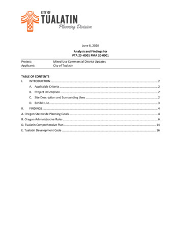
Figure 3 shows the planetary gear arrangement used in these transmissions - the figures are the numbersof teeth on the gears for model 35; those encircled are for model 8. Figure 4 is a schematic of thetransmission.Figure 2 Cutaway section of Borg-Warnermodel 35 transmissionFigure 3 Ravigneaux gearset usedby Borg-WarnerFigure 4 B-W model 8 and 35 transmission schematicThe arrangement of hydraulically actuated clutches and brakes of the actual transmission are difficult,if not impossible, to reproduce mechanically in Meccano, so an alternative scheme is required where allthe clutched and braked elements are accessible externally.Such a scheme was devised and the layout added into a spreadsheet with descriptive data and gear ratiocalculation charts, as shown in figure 5.Development of the Meccano ModelThe Ravigneaux gearset is defined as an epicyclic gear arrangement having two sun gears and pairs ofmeshing planet gears, one planet meshing with one of the sun gears, the other meshing with the annulusgear, as shown in the diagrams, figures 3, 4 & 5. The primary train being s1, p1, p2a & a, with thesecondary train: s2 & p2b, p2a and p2b being fixed on the same shaft.The obvious starting point was to consider which Meccano pinions would mesh between the adjacentradial and peripheral holes of an 8-hole bush wheel acting as one side of the planet carrier, with a57-tooth gear for the other side.2www.selmec.org.uk
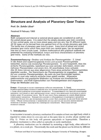
Figure 5 Gear schematic, spreadsheet and chartsThis soon proved impractical, so a 6-hole bush wheel was considered for the carrier element.After trying many options and checking the resultant ratios, the best combinations were 19:19 & 22:15.In theory, the 22:15 combination is not meant to mesh together, because the 22-tooth pinion is designedto mesh with the 55-tooth wheel, an equivalent centre distance of 37 teeth. Standard Meccano gears are38DP (Diametral Pitch), so one or both gears have to be profile shifted (non-standard) to mesh effectivelyat ½” spacing. Similarly, the 15-tooth pinion is designed to mesh with the 60-tooth wheel, a centredistance equivalent to 37.5 teeth. So one or both are non-standard. Despite all this, 22:15 do mesh quitewell together!This combination was used as the secondary train in a Ravigneaux model with 19-tooth pinions as theprimary train, shown close-up in figure 6. This gearset was developed in a “breadboard” or prototypemodel, shown in the general view figure 7.www.selmec.org.uk3
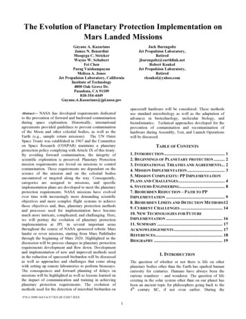
Figure 6 Prototype model Ravigneaux gearsetSecondary sun gear s2Clutch function shaft (D)Planet carrier brake (D)Primary sun gear s1Secondary sun gear brake/clutch (C)Primary sun gear clutch (B)Input clutch (A)Input shaftRavigneux planetary gearsetPark brake (E)& annulus aDetent mechanism(Red neutral)Intermediate trunnion bearingBrake function shaftSecondary planet p2bBrake/clutch function relay crankOutput shaftPrimary planet p2aPrimary planet p1Figure 7 General view of the prototype Ravigneaux gearbox in 2nd gear, with elementsidentified in accordance with the notations given in figure 5The prototype model formed the basis for developing the principle of using a sliding shaft with rotating½” pinions attached, as the clutching elements, and a second sliding shaft with fixed narrow faced ½”pinions, for the braking functions. A relay crank connects these two shafts such that they slide in oppositedirections.4www.selmec.org.uk
The clutch elements are 57-tooth gears, with ‘B’ attached to the primary sun gear (s1) shaft and ‘C’ to thesecondary sun gear (s2) by socket coupling. The sliding 19-tooth pinions are set-up so as to connectsequentially, the input with s2 (reverse gear), input with none (neutral), input with s1 (first gear), inputwith s1 (second gear) and input with s1 & s2 (third gear – direct drive). This sequence satisfies the clutchfunctions described in the block chart of figure 5.Simultaneously, the brake relay shaft slides to engage in the holes of the 2½” ring gear (park), then thenarrow face 19-tooth pinions engage with the planet carrier 57-tooth gear ‘D’ (reverse), none (neutral),planet carrier 57-tooth gear ‘D’ (first gear), 57-tooth gear ‘C’ (second gear), completing the brakefunctions shown in the chart of figure 5.This sliding action produces the shift sequence: P-R-N-D1-D2-D3 as required. A 2½” faceplate carryingthe 2½” ring gear forms the gearbox output. A spring loaded pivot bolt passing over a suitably spacedstack of ½” pulleys, detents the selected gear positions. The whole assembly is supported between two2½” x 2½” flat plates attached to a 5½” x 2½” flanged plate.After much tedious experimentation to achieve the correct sequencing, spacing between gears andbacklash reduction in the sliding elements, the prototype model proved the principles of operation.However, using a bush wheel and a bushed 57-tooth gear as the planet carrier, made the assembly longerthan I wanted, also, the 15-tooth planet pinions were a compromise to achieve clearance with the 19-toothbrake shaft pinions. The ratios achieved were: 3:1, 1.66:1, 1:1 and 2.05:1 reverse, not quite as good a ratioset as those achievable by using 19-tooth pinions throughout - see chart figure 5, case 2.Figure 8 is a plan view showing the clutch function shaft in more detail. Figure 9 shows, in close-up,the brake function shaft anti-rotation coupling/control rod and the detent spring mechanism.Figure 8 Showing clutch function shaft - in 3rd gearwww.selmec.org.uk5
Figure 9 Showing brake shaft anti-rotation coupling on gear selector rod and detent springThe next stage was to develop a definitive model incorporating a more compact Ravigneaux gearset,inter-axle differential, diff-lock and Hi-Lo range change. Also, it would be desirable to overcome theclose clearance between the orbiting planet gears and the brake function gears.One method of reducing the length of the planetary set would be to obtain a 6-hole 57-tooth gear and useit as one side of the planet carrier. Stuart Borrill duly obliged with the 6-hole 57-tooth gear and a newplanetary set was constructed (fear of forgetting how the prototype was constructed, necessitated acompletely new, additional model!).Testing proved the necessity to add wheel discs to the 6-hole 57-tooth gear in order to provide betterjournals for the compound planet gear shafts. Otherwise these would skew under load and create poormeshing conditions with the mating pinions – the penalty: extra length! But this is still ¾” (19 mm)shorter than the prototype.To overcome the clearance issue, I decided to add extra narrow facewidth 19-tooth pinions, in constantmesh with the two 57-tooth brake gears ‘C’ and ‘D’, which would position the brake function shaftfurther away from the planetary set. A peripheral advantage of doing this is that it facilitated the 19-toothplanetary set with its preferable ratio’s.There was insufficient space to accommodate the prototype detent mechanism, so a more compact systemusing stacked large spring supports was devised and an axial plunger type detent pin employed, made-upfrom a collared, spring loaded 1” axle rod, journalled in a short coupling, as shown in figure 12.These improvements and changes were built into a different mounting framework, which I chose to baseon 2½” triangular end plates extended with square and triangular plates at each end.This enables the shafts to be wrapped into the most compact arrangement. A central 2½” triangular platesupports the input and planetary shafts, also providing journals for the control and detent rods.The whole is mounted onto a 2½” x 5½” flanged plate for convenience and stiffness. Additionallongitudinal ties of 5½” double bent strip and narrow angle girder provide extra support and stiffness.A high-low range gear change using narrow faced 19-tooth and 38-tooth gears and a spur gear differentialwith lock completed the gearbox as shown in figure 10.Other details are shown in figures 11, 12 and 13. ‘Drivers-side view’ refers to left-hand drive application.6www.selmec.org.uk
Gearshift leverRange change leverDiff-lock leverHi-Lo range change gearsInput drive couplingPlanetary output gearDrive motorFront output6-Hole 57t gearDiff-lockSpur gear inter-axle differentialRear outputFigure 10 General view of Ravigneaux transmission in 1st gearFigure 11 Close-up of ‘compact’ Ravigneaux gearsetwww.selmec.org.ukFigure 12 Detail of detent rail - 1st gear position7
Figure 13 Drivers-side view showing clutch/brake relay crank in 1st gearThe ratio comparison of model to vehicle is given below. It’s not a bad match since I lost two speeds!- Meccano Model verse8HighRange- H1 Alpha Hummer -www.selmec.org.uk
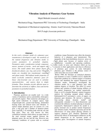
Figure 14 Ravigneaux transmission in 1/6 scale H1 Hummer chassisConclusionFigure 14 shows the Ravigneaux transmission installed in the Hummer chassis. Despite its size, it fittedwithin the frame very easily, with the controls nicely positioned.So far, it has proved sufficiently robust for this heavy model and durable in operation. Gear shifting canbe executed on the move easily and with little loss of momentum. A great improvement over the 5-speedcrash change box, which discouraged one from making gear changes!» This article 2006 Alan Wenbourne.www.selmec.org.uk9
transfer case. A planetary gearbox would have been the closest to modelling an automatic, but I resisted this because of the size and complexity of creating such a gearbox using 3½" ring gears. Since the 2½" ring gear became available I began formulating some ideas for using the smaller ring gear in a Ravigneaux configuration.