Transcription
BOOKLET OFORATING EFFICIENCY CURVES - c u v a s
TABLE OF CONTENTSIntroduction to GratingsGrating EfficiencyHigher Order ConsiderationsPolarizationGrating Anomalies and TypesGrating CareGratings OverviewGratings for 77700 Series Monochromator/SpectrographUltraviolet GratingsVisible GratingsNear Infrared GratingsInfrared GratingsGratings for 77250 Series 1/8 m MonochromatorUltraviolet GratingsVisible GratingsNear Infrared GratingsInfrared GratingsGratings for 77200 Series 1/4 m f /lonochromatorUltraviolet GratingsVisible GratingsNear Infrared GratingsInfrared GratingsGratings for 77400 Series 1/8 m SpectrographUltraviolet GratingsVisible GratingsNear Infrared GratingsUnmounted GratingsUltraviolet GratingsVisible GratingsNear Infrared GratingsInfrared 7885
INTRODUCTION TO GRATINGSCHOOSING YOUR GRATINGThe choice of grating for any spectroscopic system depends on theapplication and must be made as one step in an iterative process of system design. The radiation source, radiation detector, polarization of radiation, spectral range of interest and desired resolution all play a role in grating selection. Our monochromators and spectrographs are designed toallow easy grating interchange and we supply a wide range of gratings.Sometimes the solution is to select more than one grating.This booklet discusses some properties of Oriel diffraction gratings, andshows typical efficiency curves. We hope it helps you select the best grating for your application.GROOVE DENSITYOriel gratings are available in various groove densities (i.e. lines/mm)and blaze wavelengths. The blaze wavelength is the wavelength wherethe grating efficiency is enhanced by shaping the grating grooves. (Werefer to our holographic gratings as blazed for convenience. This is notstrictly true though recent production techniques allow modification of thesimple symmetrical sinusoidal groove shape to enhance efficiency over alimited spectral region.) Gratings for the UV and visible are available withgroove densities from 200 to 2400 I/mm, though not for all instruments.Gratings for the near infrared are 600 I/mm and then infrared gratingshave lower groove densities.Groove density, bandpass and resolutionHigher groove densities give higher reciprocal dispersion and thereforehigher resolution. The monochromator bandpass with a 2400 I/mm grating (and slits with widths above 50 \im) is half that of the same arrangement with a 1200 I/mm grating. The resolution with the 2400 I/mm gratingis twice that with the 1200 I/mm grating. This simple relationship is notaccurate for slitwidths below 25 to 50 n.m (depends on monochromatorand grating) as the optical aberrations begin to play a role in the bandpassand resolution. Actual bandpasses are tabulated in the Volume II catalog.Groove density and stepper motor wavelength drivesBecause we use a sine drive in our 77250 and 77200 Monochromators, each step of the stepper motor changes the wavelength by aconstant amount; 0.1 nm for a 1200 I/mm grating in the 77250 or 77200.The wavelength increment per step depends on the grating; with a coarsergrating (i.e. one with a lower groove density) the wavelength incrementper step is larger. The wavelength increment per step is given by0.1 X 1200/gden nmDispersionAs usual the first law of physics "You don't get something for nothing"applies. You may gain resolution by going to a higher groove density grating, but you lose spectral range. This is easy to see for our 77400 1/8 mSpectrograph where the 77411 1200 I/mm grating has a reciprocal dispersion of around 6.3 nm/mm, and spreads 6.3 x 12.5 79 nm over a 12.5mm long diode array or 6.3 x 25 158 nm over a 25 mm long diode array.For our 1/4 m Monochromator/Spectrograph, the same 1200 I/mm gratinghas a reciprocal dispersion of around 3.2 nm/mm, and spreads 80 nm.The dispersion of a grating changes inversely with the groove density.If the groove density is halved, the dispersion is doubled. For example, a600 I/mm grating spreads approximately 320 nm over a 25 mm long diodearray, and a 300 I/mm grating spreads approximately 640 nm.Because linear dispersion varies with incident angle, the dispersion of a600 I/mm grating over a diode array is not exactly double that of a 1200I/mm grating over the same diode array.Groove density and spectral range for a monochromatorA monochromator mechanism can only tilt the grating through a limitedangle, from -0 to 45 in the 77200. The angle and groove density determine the transmitted wavelength, you can then use the grating equationand the maximum angle determined by the mechanism, to find the longestpossible wavelength.Since the grating can be tilted down to 0 , the lowest possible wavelength, ca. 180 nm, is set by the transmittance of the air (ca. 150 nm for anitrogen flushed monochromator).Table 2 Longest Wavelength In First Order Determined by theMechanism of the MonochromatorLongest Waveiengtti in nmGrating Groove77250 1/8 m77200 1/4 mDensity (i/mm) Monochromator 960019200N/A77400 1/8 mSpectrograph77700 00N/AN/AN/AN/AWhere:g , Groove density of the grating in useE.g., with a 2400 i/mm grating, you get a 0.05 nm increment.250 LONG BEACH BLVD., P.O. BOX 872, STRATFORD, CT. U.S.A. 06497 . TEL: (203) 377-8282 - FAX: (203) 378-2457 . ELECTRONiC MAIL: 2002300033600
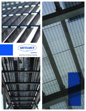
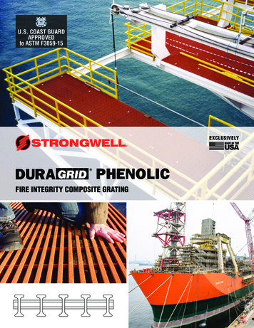
GRATING EFFICIENCYGRATING EFFICIENCYIt would be wonderful to have efficient gratings to cover 185 to 3000 nmin first order. Unfortunately due to diffraction physics, gratings only havehigh efficiency over a limited spectral range. Groove shaping techniques("blazing") allow selection of the high efficiency range. We have 1200I/mm gratings where groove shaping has been used to give high efficiencyat 250 nm. Other 1200 I/mm gratings are optimized for 500 nm.The efficiency curves starting on page 12 show how the measured efficiency falls from the maximum at the blaze wavelength. As you can seefrom the curves, some gratings are very efficient over a limited wavelengthrange; this means for radiation at any wavelength in this range most of theincident beam is diffracted into the first order, and through the monochromator (set for that wavelength).Please use the curves as a guide and not as absolute data. Themeasurements which led to all the data used a particular monochromatorgeometry; performance in each of our instruments will differ slightly fromthis data as the geometries are not exactly the same. This is of particularimportance with spectrographs.If light of 500 nm is measured with a diode array detector when thecenter wavelength on the detector is 400 nm, the signal will differ from thatmeasured when the center wavelength is displaced, for example, to 600nm. For this reason sections of emission spectra taken at different centerwavelengths cannot be simply spliced together to make up a wider spectral range.We list the usable and primary efficiency ranges for each grating.The usable range is the range in first order for which the grating has anefficiency of more than 10% (for unpolarized radiation), and the primary isthe range in which the grating has an efficiency of more than 20% (forunpolarized radiation).In summary then, there are three spectral ranges. Wavelengths increasing to the theoretical maximum (see page 9 fora brief description of "theoretical maximum") Maximum range determined by the mechanical rotation limit of themonochromator. The shaded area of our curves are beyond themechanical limit of the instrument. The efficiency limited spectral range somewhat arbitrarily dividedinto primary ( 20%) and usable ( 10%) ranges.1LDRIEL90-INSTRUMENTS8070-15? ozLUoLLUlUPRIMARY-*-EFFICIENCY RANGE6050-i40302010-/r100 200 300 400 N500600700 800 9001000 1.21.41.61.82.02.22.42.6USABLERANGEMAXIMUM RANGEDETERMINED BY*MECHANICAL ROTATION*LIMIT OF MONOCHROMATORFig. 1 Typical grating efficiency curve showing the various spectral ranges.The wavelength scale Is changed at 1000 nm (1 m).For further information on any grating in tills cataiog CALL (203) 377-8282
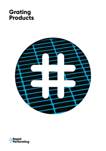
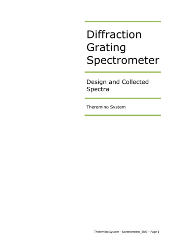
HIGHER ORDER CONSIDERATIONSWhen you set a monochromator at 600 nm, any radiation present at200 nm or 300 nm will pass through the monochromator. Similarly, if thegrating is set for 1000 nm, then 500 nm, 333 nm, 250 nm and 200 nmradiation also pass through the monochromator. In general when themonochromator is set for wavelength X, radiation at X/1, X/2, X/S, etc. canpass through. The denominator 1, 2, 3, etc. is called the order of diffraction. Radiation at X is called first order radiation and is usually what wewant (as we have set the monochromator at X\). Radiation at XJ2 is calledsecond order radiation, X/3 third order, etc. All radiation at X/2, X/3, X/4,etc. can be collectively referred to as higher order radiation.EFFICIENCY OF HIGHER ORDER DIFFRACTIONThe efficiency curves in this booklet are for first order radiation.Fig. 2 shows typical efficiency curves for first, second and third orders.The curves for the higher orders have lower peaks and show less structure than the first order curve. The second order curve peaks at /IB/2, thethird order peaks at XB/3, etc. (XQ Blaze wavelength). When the monochromator is operating efficiently in first order it is also efficient for 2nd,3rd, etc. orders. You can make use of this behavior to extend the usefulrange of a grating to shorter wavelengths.HIGHER ORDER DIFFRACTION CAN BE USEFULHigher order diffraction can be used for more efficient operation at lowwavelengths. For example, if you have a grating blazed for 500 nm in firstorder, then the curve shows very low first order efficiency at 250 nm, so bycranking the monochromator down to 250 nm you will get very littlethroughput. The reason that the grating has low first order efficiency at250 nm is that, because of the blazed groove shape, 250 nm radiation isbeing efficiently diffracted into the second order! You can get much betterefficiency at 250 nm by operating this grating in second order with themonochromator set at 500 nm. (This will only be useful if you have noproblem with 500 nm radiation or can filter it out from the desired 250 nmradiation.)In general, when the monochromator is set for XB/2, the first order efficiency is so low, very little radiation passes through. For more efficiency atwavelength XB/2, you can set the monochromator at XQ, and use secondorder diffraction. There the A,B/2 efficiency is much greater.PROBLEMS:DETECTORRECORDS -ABROADBANDTRANSMITTINGLENS-\XI 231ST2ND3RDORDER ORDER ORDERBROADBANDSOURCE MONOCHROMATOR50 ozLU40/A /\l\\SOLUTIONS:1st\,, ORDER-oLLLLLU( T ) LENS MATERIAL CUTSOFF X/2. XJ3. ETC.3020 \5001000\l 2ndV ORDERV 3rd X c ORDER100y1500- V- ''V.200025003000350040 DOWAVELENGTH (nm)Fig. 2 Typical grating efficiency curves for first, second and third orders. ORDER SORTING FILTERCAN BE ON INPUT OROUTPUT SIDE.DETECTORSENSITIVEONLY TO XFig. 3 When detecting very low signals In the presence of an Intense shortwavelength background, use the filter on the Input side. If the filter Ison the output side, close to the detector, then the higher order radiation coming through the monochromator can cause the filter to fluoresce and this fluorescence will t e detected. Of course the fluorescence will be due only to the narrow band of higher order radiationthat passes through the monochromator, but If the filter is close to thedetector, the detector can collect a lot of the Isotroplcally emittedfluorescence. If the filter Is on the Input side it will also fluoresce, butthe monochromator collection angle and narrow bandpass will reducethe fluorescence reaching the detector. When using the monochromator as a filter for an intense source, the filter may be better on the output side as this reduces the power on the filter.250 LONG BEACH BLVD., P.O. BOX 872, STRATFORD, CT. U.S.A. 06497 - TEL: (203) 377-8282 - FAX: (203) 378-2457 - ELECTRONIC MAIL: 73163.1321@compuserve.com
HIGHER ORDER RADIATION CAN BE A NUISANCEFor meaningful spectral measurements you should be careful toremove unwanted orders, particularly if the input radiation is intense or thedetector more sensitive at the higher order.Many radiometric and spectrophotometric measurements are erroneous because what was thought to be a measurement with a singlewavelength was actually a measurement using radiation at that wavelength contaminated with higher order radiation. This happens frequentlywith an arc or tungsten halogen source and photomultiplier operating inthe 750 to 900 nm region. The sensitivity of most photomultipliers falls offrapidly as you go beyond 800 nm, but the sensitivity to second order radiation (385 to 450 nm) is deceptively high as you scan from 750 to 900 nm.In this case you might want to use our 51294 Filter which cuts on at 505nm, blocking the unwanted 385 to 450 nm band. See page 2-79 ofVolume II for a selection of Order Sorting Filters.HIGHER ORDER CONSIDERATIONSIf you calibrate our 1/4 m Spectrograph/lnstaSpec IV CCD combination with a calibrated source then the counts at any wavelength X are(ignoring stray light):Cx ki Rx Ex Tx k2 Rxy2 \J2 Tx/2 etc.Where:Rx Reponsivity of the array (in counts/joule) at wavelength XTx Transmission of the spectrograph at wavelength XEx Incident energy per unit bandwidth through the spectrographentrance slit during the array "exposure time". For continuoussources, Ex Ix t, where t is the exposure time of the array andIx is the source irradiance in watts cm-2nm-i on the slit.ki Normalizing constant which relates the energy through the slitto that falling on one pixel of the array. It includes thedispersion of the grating at X, the entrance slit width, the pixel(and total capture) dimensions and the imaging geometry ofthe spectrograph.Values for X/2 are those for the second order radiation, and the "etc."takes care of any higher orders.We can simplify the expression to:cx includes all the factors in the previous equationThe whole purpose of radiometry is to measure an unknown source byfirst measuring a known source. The whole irradiance program is basedon being able to say that at any wavelength X (corresponding to say pixel#123) the irradiance from the unknown, luk, is given by:luk Ik X Cuk/CkI.e. if the unknown source produced three times as many counts atpixel #123 as the known source for the same exposure time (Cuk 3Ck),then you know that the irradiance of the unknown is three times that of theknown at that wavelength X.But, if you let the higher orders be mixed in, then you don't know whatthe counts at pixel #123 are due to, either for the known source or for theunknown. In a simple example, if the known (calibration source) has nosecond or higher order radiation, then Ck, the number of counts for pixel#123, can be expressed as:Ck Cx ExNow suppose we have an unknown that may or may not have secondor higher order radiation and we measure Cjk counts at pixel #123, wedon't know anything except that pixel #123 recorded some mixture of radiation at X, X/2, X/3, etc.Unfortunately, for any quantitative measurements we must know thatthe known and unknown sources have the same spectral distribution (inwhich case why bother with an expensive spectral radiometer), we mustknow that there is no higher order radiation at the wavelengths of interest,or we must use order sorting filters and record a piece of the spectrum ata time.STRAY LIGHTIn practice, a second type of stray light is a big problem with broadbandsources and detectors. It is due to the dispersed radiation inside themonochromator/spectrograph, and its level depends on the design of thebaffles and spectrograph, and the finish (absorbing black paint) inside theinstrument. Even if the grating is perfect, this stray light will be there andcould be troublesome. Spectral filters should be used to remove as muchof it as possible. Or, you can use a double monochromator. You can lookon one monochromator of a double monochromator as a tunable narrowspectral filter.Cx cx Ex -(- Cx/2 Ex/2 -t- etc.Where:For furttier information on any grating in tliis cataiog CALL (203) 377-8282
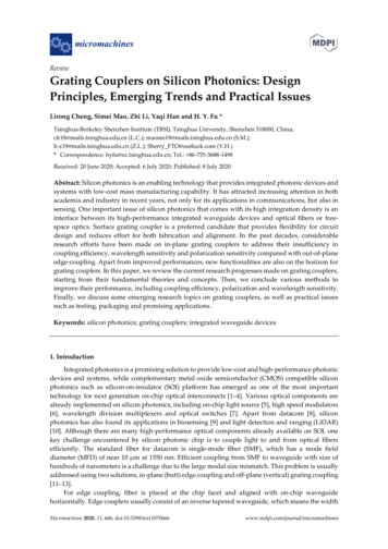
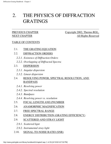
POLARIZATIONPOLARIZATIONThe diffraction efficiency from a grating usually depends on the polarization of the radiation incident on the grating. There can be significant differences between the efficiency for radiation with the electric field vectorparallel to the grating grooves and radiation with the electric vector perpendicular to the grooves.Radiation with the electric vector restricted to a specific direction is linearly polarized. Linearly polarized radiation with the electric vector parallelto the grooves is p polarized and radiation polarized perpendicular to thegrooves is s polarized. For our monochromators and spectrographs, ppolarized radiation has the polarization axis parallel to the entrance slit. Inmost laboratory applications with the instrument sitting on its feet on a horizontal bench, p polarized radiation is vertically polarized.(Note that this historical definition of s and p polarization for diffractiongratings does not follow the general rules for s and p polarization foroptics where the plane of incidence rather than the grooves are used todefine parallel and perpendicular.)60.0-\URIEL XINSTRUMENTS52.5-/TOTAL. UNPOLARIZED INPUT\V\\\,l\45.0-/ /37.5-X POLARIZED!TO GROOVES(S-PLANE) 1 \/ A// 1/1/1/1 /1 ' 30.0-22.5- 1 \»Ml* 1 ll /POLARIZED IITO GROOVES(P-PLANE)15.0-\ ' ' / \7.5- ' - 200300400500600 W. 7008009001000WAVELENGTH (nm)Fig. 5 This shows the three polarization curves for the scan from Fig. 6 onthe next page.-POLARIZEDMAY BE PARTIALLYPOLARIZEDDEPENDING ONGRATING ANDWAVELENGTHFig. 4 The direction of p, s and unpolarized radiation entering and exitingthe 77200 Monochromator.Polarization and EfficiencyMost of our graphs for any grating have two separate efficiency curves,one for radiation polarized parallel to the grooves and one for radiationpolarized perpendicular to the grooves.We will discuss three aspects of this polarization dependence1. Efficiency considerations for polarized input radiation.2. The efficiency curves for one polarization are "smoother".3. When you use unpolarized light, the output from the monochromatormay be partially polarized.1. Efficiency considerationsIf your source is linearly polarized and efficiency is important, then youshould make sure that you have the most efficient orientation forpolarization to grating. You can ensure this by rotating the source,rotating the polarization, or rotating the spectrometer. Rotating thepolarization of a large laser system using a half wave plate (Volume IIIpage 3- 28) or achromatic retarder (Volume III page 3- 30), is oftensimpler than rotating either the laser or spectrometer.2.Curve smoothnessTypically the efficiency curve for p polarized light peaks slightly lowerthan nominal blaze wavelength and smoothly declines to 0 at aboutthree times the blaze. The curves for p polarized light are generallysmooth, without dramatic changes in direction or sharp features. Thecurves for s polarized light peak slightly above nominal blaze and250 LONG BEACH BLVD., P.O. BOX 872, STRATFORD, CT. U.S.A. 06497 - TEL: (203) 377-8282 FAX: (203) 378-2457 - ELECTRONIC MAIL: 73163.1321@compuserve.com
decline but can recover dramatically and show good efficiency rightout to the theoretical maximum diffraction wavelength. The s polarization curves can show sharp features, anomalies, which complicatedata deconvolution from spectral scans. If you are measuring a spectral feature close to an anomaly, then the real feature may be dramatically distorted. If possible, you should select a grating (or polarization)which has no significant anomaly in the spectral region of interest.Most radiometric or spectrophotometric measurements are relative. Areference scan of a calibrated light source (or scan without sample) isused to evaluate the unknown. Because of the polarization relatedefficiency differences, it is important that the reference and "unknown"radiation have exactly the same polarization properties. We recommend the use of a diffuser at the input to the monochromator, preferably an integrating sphere, for the most accurate measurements.3. Polarization of the output radiationWhen you pass unpolarized light through a monochromator, the output monochromatic beam may be polarized. The performance ofmany optical elements depends on polarization. This is particularlytrue of dielectric reflectors used at non normal incidence. You shouldbe cognizant of the polarization effects when selecting componentsfor the path of the radiation from the monochromator. You should alsodistinguish between the use of s and p polarization for gratings andmonochromators and the general use of the terms in optics.The sensitivity of most detectors does not depend on the polarizationof the detected radiation. Side-on photomultipliers do show somepolarization dependence.EJRIELINSTRUMENTSLIGHT SOURCESPECTRAL OUTPUTPHOTOMULTIPLIERRESPONSEAn Example: Diode Laser MeasurementsThe 77234 600 I/mm grating blazed at 1 nm is a popular grating formeasurement of diode laser spectral characteristics. Diode lasers typicallyhave a polarized output (with greater than 50:1 ratio). For the visible laserdiodes this grating is more than 2 times as efficient for p polarized radiation than for s polarization. At 850 nm the difference in efficiency is inconsequential while at 1.3 and 1.5 im radiation, the s polarization is diffractedmore efficiently.The radiating area of many diodes is rectangular, and the polarizationdirection is parallel to the long dimension of the diode. For direct couplingof the diode output to the slit of a spectrograph, it is more efficient to couple the long dimension of the emitting area to the long dimension of theslit. With the 1.3 and 1.5 m infrared diode lasers, this means that forhighest total efficiency, coupling and grating, you must align the diode tothe slit and rotate the polarization of the infrared radiation.ACTUALSCAN400500600700WAVELENGTH (nm)Fig. 6 The bottom graph shows an actual scan of a calibrated lamp outputwhen used with the 77296 Grating and a PMT.For furttier information on any grating in ttiis cataiog CALL (203) 377-8282
GRATING ANOMALIES AND TYPESGHOSTS AND ANOMALIESAnomalies are sudden increases or decreases in the efficiency vs.wavelength curve. They are a result of the interaction of the electric fieldsof incident and diffracted beams with each other and with the metal coatedgrooves of the grating. They are not a defect of the grating but aninescapable consequence of the diffraction physics of blazed gratings.They were first documented by Wood and so are sometimes calledWood's Anomalies. Fig. 7 shows a typical grating efficiency curve withanomalies. Fig. 6 shows the effect these anomalies have on the recordedspectrum of a typical tungsten halogen source.GRATING ANOMALIES1:11POLARIZED 1 TO GROOVES(S-PLANE)POLARIZEDJl TO GROOVES o(P-PLANE)LULU .22.4WAVELENGTH ( m)The best ruled gratings can also exhibit ghosts. You see these mostclearly when using a high power monochromatic input, such as a laserused for Raman studies. In addition to the strong main line in the outputspectra the grating may produce faint satellite lines equally spaced oneach side of the main line. Rowland ghosts are close to the expected lineand Lyman ghosts are well separated from the line. Both are due to periodic errors in the grating grooves caused by minor defects in the rulingmachine. The intensity of the brightest ghost should be less than 0.0003times the line intensity. Knowing that all ruled gratings suffer from ghostsallows you to avoid interpreting these faint signals as weak but real spectral signatures. Ghosts appear equally spaced on both sides of the mainline. Holographic gratings do not suffer from ghosts.RULED OR HOLOGRAPHIC?Grating masters are either ruled using a ruling engine with an extremelyfine cutting tool, or produced by recording interference fringes in photoresist. The different techniques cause some differences in the performanceof ruled and (interference or) holographic gratings. Additionally,because there are few combinations of photoresist and high power laserssuitable for grating production, holographic gratings are only available withhigher groove densities. (The groove density depends on the fringe spacing which depends on the laser wavelength).We recommend holographic gratings for work in the UV and throughthe visible to ca. 600 nm. They scatter less stray light into the signal direction, so, even if the efficiency is lower than that of the competing ruledgrating, the holographic grating may give better signal to noise performance. (The actual signal to noise will depend on the spectral content ofthe incident light and the detector.)Holographic gratings have an additional advantage; they do not sufferfrom ghosts, so interpretation of line spectra is simplified.Fig. 7 Typical grating efficiency curve showing Wood's anomalies.Some gratings exhibit prominent anomalies; others with different blazedesign, have no significant anomalies. Anomalies are much more troublesome for s- polarized radiation (though p polarized radiation can exhibitanomalous behavior also.250 LONG BEACH BLVD., P.O. BOX 872, STRATFORD, CT. U.S.A. 06497 TEL: (203) 377-8282 FAX: (203) 378-2457 ELECTRONIC MAIL: 73163.1321@compuserve.com
iJRIElGRATING CARECARE AND CLEANING OF GRATINGSGrating cleanliness is important for efficiency but even more importantfor stray light rejection. A dirty grating will still diffract, but there will be ahigh stray light background as the radiation scatters or reflects off the dirt.We have not found a satisfactory method of cleaning gratings thatdoesn't cost more than the grating. Usually attempts at cleaning the surface result in worsening the problem. The grooved replicated surface isfragile and can peel off. The grooves trap all sorts of small particles. Wedo not recommend solvent baths, ultrasonic cleaning or strippable coatings.If you have appropriate safety equipment and environmentally safemeans of chemical disposal then you can clean fresh fingerprints from agrating using high purity xylene or toluene and extreme care. General purpose solvent will leave a residue. The solvent must only flow over the grating surface. Contact with the metal holder or adhesives can transfer contaminants from these to the grating face. When we attempt this cleaningwe usually find that the learning curve costs us most of the gratings wewanted to clean!So, take care of your gratings. Never touch the surface Don't wipe the grating - even gently Don't wrap gratings in tissue Never leave a grating face up on an open bench Store gratings in a dessicatorGrating BlemishesThe cosmetic appearance of a grating (as distinct from dirt and dust onthe grating) does not correlate with performance. Rowland found that hisbest gratings were the ones with the worst visual appearance! Some ofthe most efficient gratings seem to have bands. These originate in the ruling of the master and may be due to the cutting tool picking up a tinyshard.If the application is limited to a narrow spectral region, then the gratingchoice is simple; the most efficient grating in that region is the best choice.WHY DON'T WE OFFER HIGH GROOVE DENSITY GRATINGSFOR THE INFRARED AND WHY DO OUR GRATINGS HAVE AMAXIMUM GROOVE DENSITY OF 2400 I/mm?The practical difficulty in producing a grating with groove density above2400 I/mm (i.e. line spacing of less than 0.42 im) is just now beingremoved by new lithographic techniques or short wavelength holography,but grating physics place a limit on the use of higher groove density gratings.The grating equation is:a (sin I sin D) m X*Where:maXID thethethethetheordergroovewavelengthangle of incidenceangle of diffractionSince we are only considering first order, m 1. For a 1200 I/mm grating, a 833 nm. The maximum possible value of the sum of two sines is2. Therefore the maximum possible value of X to satisfy833 (sin I sin D) Xis obviously 1666 nm. So even if you could design a monochromator withD -90 and I -90 , the longest wavelength you could possibly get in firstorder from any 1200 I/mm grating is 1666 nm. Likewise with a 2400 I/mmgrating the maximum is 833 nm. Practical considerations restrict theangles D and I so the longest usable wavelength is lower than this theoretically possible maximum. Our 1/4 m 77200 Monochromator allows useto 1200 nm with a 1200 I/mm grating and 600 nm with a 2400 I/mm grating, in both cases an impressive 72% of the theoretically possible maximum. A 4000 I/mm grating would only be useful to 360 nm. And of coursethe theoretical limit is why we offer only low groove density gratings for theinfrared.* Different definitions of positive and negative angles (with respect to thegrating normal) can lead to confusion In using this equation.For furttier Information on any grating in ttils catalog CALL (203) 377-8282
GRATINGS OVERVIEWWavelength RegionBlazeWavelengthLine Density(I/mm)(nm)PrimaryUsableGratings for 77700 Series Monochromator/Spectrograph175-700 nm200180-500 nm600180-700 nm250200-700 nm2400175-1000 nm180-650 nm1200'250200-1400 nm180-1400 nm1200350250-1300 nm250-1600 nm400600250-1150 nm245-1500 nm300500250-1050 nm1800500300-1050 nm450-1400 nm400-1400 nm12007506001000600-2500 nm550-2500 nm550-2400 nm2001000600-2200 nm4001200700-2500 nm650-3000 nm1-4nm30020001.1-3.4 m2.5-9.5 nm15040002.5-9 nm4.5-21 nm754.5-20 nm7000Gratings for 77250 Series 1/8 m Monochromator180-500 nm175-700 nm6002002400250200-500 nm180-500 nm175-1000 nm180-650 nm1200250200-1000 nm180-1000 nm1200350300-750 nm250-750 nm1800500450-1000 nm400-1000 nm1200750
The wavelength increment per step depends on the grating; with a coarser grating (i.e. one with a lower groove density) the wavelength increment per step is larger. The wavelength increment per step is given by 0.1 X 1200/gden nm Where: g , Groove density of the grating in use E.g., with a 2400 i/mm grating, you get a 0.05 nm increment.