Transcription
Diffraction Grating Handbook - Chapter 12.THE PHYSICS OF DIFFRACTIONGRATINGSPREVIOUS CHAPTERNEXT CHAPTERCopyright 2002, Thermo RGL,All Rights ReservedTABLE OF CONTENTS2.1.THE GRATING EQUATION2.2.DIFFRACTION ORDERS2.2.1. Existence of Diffraction Orders2.2.2. Overlapping of Diffracted Spectra2.3.DISPERSION2.3.1. Angular dispersion2.3.2. Linear dispersionRESOLVING POWER, SPECTRAL RESOLUTION, AND2.4.BANDPASS2.4.1. Resolving power2.4.2. Spectral resolution2.4.3. Bandpass2.4.4. Resolving power vs. resolutionFOCAL LENGTH AND f/NUMBER2.5.2.6.ANAMORPHIC MAGNIFICATION2.7.FREE SPECTRAL RANGE2.8.ENERGY DISTRIBUTION (GRATING EFFICIENCY)2.9.SCATTERED AND STRAY LIGHT2.9.1. Scattered lignt2.9.2. Instrumental stray light2.10. SIGNAL-TO-NOISE RATIO hapter2.asp (1 of 23) [6/15/02 6:27:52 PM]
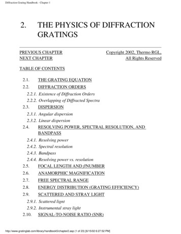
Diffraction Grating Handbook - Chapter 12.1. THE GRATING EQUATION [top]When monochromatic light is incident on a grating surface, it isdiffracted into discrete directions. We can picture each grating groove as beinga very small, slit-shaped source of diffracted light. The light diffracted by eachgroove combines to form a diffracted wavefront. The usefulness of a gratingdepends on the fact that there exists a unique set of discrete angles along which,for a given spacing d between grooves, the diffracted light from each facet is inphase with the light diffracted from any other facet, so they combineconstructively.Diffraction by a grating can be visualized from the geometry in Figure 21, which shows a light ray of wavelength λ incident at an angle α anddiffracted by a grating (of groove spacing d, also called the pitch) along anglesβm. These angles are measured from the grating normal, which is the dashedline perpendicular to the grating surface at its center. The sign convention forthese angles depends on whether the light is diffracted on the same side or theopposite side of the grating as the incident light. In diagram (a), which shows areflection grating, the angles α 0 and β1 0 (since they are measured counterclockwise from the grating normal) while the angles β0 0 and β–1 0 (sincethey are measured clockwise from the grating normal). Diagram (b) shows thecase for a transmission grating.By convention, angles of incidence and diffraction are measured fromthe grating normal to the beam. This is shown by arrows in the diagrams. Inboth diagrams, the sign convention for angles is shown by the plus and minussymbols located on either side of the grating normal. For either reflection ortransmission gratings, the algebraic signs of two angles differ if they aremeasured from opposite sides of the grating normal. Other sign ook5/chapter2.asp (2 of 23) [6/15/02 6:27:52 PM]
Diffraction Grating Handbook - Chapter 1Figure 2-1. Diffraction by a plane grating. A beam of monochromatic light ofwavelength λ is incident on a grating and diffracted along several discretepaths. The triangular grooves come out of the page; the rays lie in the plane ofthe page. The sign convention for the angles α and β is shown by the and –signs on either side of the grating normal. (a) A reflection grating: the incidentand diffracted rays lie on the same side of the grating. (b) A transmissiongrating: the incident and diffracted rays lies on opposite sides of the grating.exist, so care must be taken in calculations to ensure that results are selfconsistent. Another illustration of grating diffraction, using wavefronts(surfaces of constant phase), is shown in Figure 2-2. The geometrical pathdifference between light from adjacent grooves is seen to be d sinα d sinβ.[Since β 0, the latter term is actually negative.] The principle of book5/chapter2.asp (3 of 23) [6/15/02 6:27:52 PM]
Diffraction Grating Handbook - Chapter 1dictates that only when this difference equals the wavelength λ of the light, orsome integral multiple thereof, will the light from adjacent grooves be in phase(leading to constructive interference). At all other angles β, there will be somemeasure of destructive interference between the wavelets originating from thegroove facets.These relationships are expressed by the grating equation(2-1)mλ d (sinα sinβ),which governs the angles of diffraction from a grating of groove spacing d.Here m is the diffraction order (or spectral order), which is an integer. For aparticular wavelength λ, all values of m for which mλ/d 2 correspond tophysically realizable diffraction orders.It is sometimes convenient to write the grating equation asGmλ sinα sinβ,(2-1')where G 1/d is the groove frequency or groove density, more commonlycalled "grooves per millimeter".Eq. (2-1) and its equivalent Eq. (2-1') are the common forms of thegrating equation, but their validity is restricted to cases in which the incidentand diffracted rays are perpendicular to the grooves (at the center of thegrating). The vast majority of grating systems fall within this category, which iscalled classical (or in-plane) diffraction. If the incident light beam is notperpendicular to the grooves, though, the grating equation must be modified:Gmλ cosε (sinα sinβ),(2-1'')Here ε is the angle between the incident light path and the plane perpendicularto the grooves at the grating center (the plane of the page in Figure 2-2). If theincident light lies in this plane, ε 0 and Eq. (2-1") reduces to the morefamiliar Eq. (2-1'). In geometries for which ε 0, the diffracted spectra lie on acone rather than in a plane, so such cases are termed conical diffraction.For a grating of groove spacing d, there is a purely mathematical book5/chapter2.asp (4 of 23) [6/15/02 6:27:52 PM]
Diffraction Grating Handbook - Chapter 1between the wavelength and the angles of incidence and diffraction. In a givenspectral order m, the different wavelengths of polychromatic wavefrontsincident at angle α are separated in angle:β (λ) arcsin(mλ/d – sinα).(2-2)When m 0, the grating acts as a mirror, and the wavelengths are not separated(β –α for all λ); this is called specular reflection or simply the zero order.Figure 2-2. Geometry of diffraction, for planar wavefronts. The terms in thepath difference, d sinα and d sinβ, are shown.A special but common case is that in which the light is diffracted back towardthe direction from which it came (i.e., α β); this is called the Littrowconfiguration, for which the grating equation becomesmλ 2d sinα,in Littrow.(2-3)In many applications (such as constant-deviation monochromators), thewavelength λ is changed by rotating the grating about the axis coincident apter2.asp (5 of 23) [6/15/02 6:27:52 PM]
Diffraction Grating Handbook - Chapter 1its central ruling, with the directions of incident and diffracted light remainingunchanged. The deviation angle 2K between the incidence and diffractiondirections (also called the angular deviation) is2K α – β constant(2-4)while the scan angle φ, which is measured from the grating normal to thebisector of the beams, is2φ α β.(2-5)Figure 2-3. A sine bar mechanism for wavelength scanning. As the screw isextended linearly by the distance x shown, the grating rotates through an angleφ in such a way that sinφ is proportional to x.Note that φ changes with λ (as do α and β). In this case, the grating equationcan be expressed in terms of φ and the half deviation angle K asmλ 2d cosK sinφ.(2-6)This version of the grating equation is useful for monochromator mounts (seeChapter 7). Eq. (2-6) shows that the wavelength diffracted by a grating in amonochromator mount is directly proportional to the sine of the angle φthrough which the grating rotates, which is the basis for monochromator drivesin which a sine bar rotates the grating to scan wavelengths (see Figure hapter2.asp (6 of 23) [6/15/02 6:27:52 PM]
Diffraction Grating Handbook - Chapter 12.2. DIFFRACTION ORDERS [top]2.2.1. Existence of Diffraction Orders.For a particular set of values of the groove spacing d and the angles αand β, the grating equation (2-1) is satisfied by more than one wavelength. Infact, subject to restrictions discussed below, there may be several discretewavelengths which, when multiplied by successive integers m, satisfy thecondition for constructive interference. The physical significance of this is thatthe constructive reinforcement of wavelets diffracted by successive groovesmerely requires that each ray be retarded (or advanced) in phase with everyother; this phase difference must therefore correspond to a real distance (pathdifference) which equals an integral multiple of the wavelength. This happens,for example, when the path difference is one wavelength, in which case wespeak of the positive first diffraction order (m 1) or the negative firstdiffraction order (m –1), depending on whether the rays are advanced orretarded as we move from groove to groove. Similarly, the second order (m 2) and negative second order (m –2) are those for which the path differencebetween rays diffracted from adjacent grooves equals two wavelengths.The grating equation reveals that only those spectral orders for which mλ/d 2 can exist; otherwise, sinα sinβ 2, which is physicallymeaningless. This restriction prevents light of wavelength λ from beingdiffracted in more than a finite number of orders. Specular reflection (m 0) isalways possible; that is, the zero order always exists (it simply requires β –α). In most cases, the grating equation allows light of wavelength λ to bediffracted into both negative and positive orders as well. Explicitly, spectra ofall orders m exist for which–2d mλ 2d,m an integer.(2-7)For l/d 1, a large number of diffracted orders will exist.As seen from Eq. (2-1), the distinction between negative and positivespectral orders is apter2.asp (7 of 23) [6/15/02 6:27:52 PM]
Diffraction Grating Handbook - Chapter 1β –α for positive orders (m 0),β –α for negative orders (m 0),(2-8)β –α for specular reflection (m 0),This sign convention for m requires that m 0 if the diffracted ray lies to theleft (the counter-clockwise side) of the zero order (m 0), and m 0 if thediffracted ray lies to the right (the clockwise side) of the zero order. Thisconvention is shown graphically in Figure 2-4.2.2.2. Overlapping of Diffracted Spectra.The most troublesome aspect of multiple order behavior is thatsuccessive spectra overlap, as shown in Figure 2-5. It is evident from thegrating equation that, for any grating instrument configuration, the light ofwavelength λ diffracted in the m 1 order will coincide with the light ofwavelength λ/2 diffracted in the m 2 order, etc., for all m satisfying inequality(2-7). In this example, the red light (600 nm) in the first spectral order willoverlap the ultraviolet light (300 nm) in the second order. A detector sensitiveat both wavelengths would see both simultaneously. This superposition ofwavelengths, which would lead to ambiguous spectroscopic data, is inherent inthe grating equation itself and must be prevented by suitable filtering (calledorder sorting), since the detector cannot generally distinguish between light ofdifferent wavelengths incident on it (within its range of sensitivity). [See alsoSection 2.7 below.]2.3. DISPERSION [top]The primary purpose of a diffraction grating is to disperse light spatiallyby wavelength. A beam of white light incident on a grating will be separatedinto its component colors upon diffraction from the grating, with each colordiffracted along a different direction. Dispersion is a measure of the separation(either angular or spatial) between diffracted light of different wavelengths.Angular dispersion expresses the spectral range per unit angle, and linearresolution expresses the spectral range per unit /chapter2.asp (8 of 23) [6/15/02 6:27:52 PM]
Diffraction Grating Handbook - Chapter 1Figure 2-4. Sign convention for the spectral order m. In this example a ook5/chapter2.asp (9 of 23) [6/15/02 6:27:52 PM]
Diffraction Grating Handbook - Chapter 1Figure 2-5. Overlapping of spectral orders. The light for wavelengths 100,200 and 300 nm in the second order is diffracted in the same direction as thelight for wavelengths 200, 400 and 600 nm in the first order. In this diagram,the light is incident from the right, so α 0.2.3.1. Angular dispersionThe angular spread dβ of a spectrum of order m between the wavelengthλ and λ dλ can be obtained by differentiating the grating equation, assumingthe incidence angle α to be constant. The change D in diffraction angle per unitwavelength is thereforeD Gm secβ(2-9)where β is given by Eq. (2-2). The ratio D dβ /dλ is called the angulardispersion. As the groove frequency G 1/d increases, the angular dispersionincreases (meaning that the angular separation between wavelengths k5/chapter2.asp (10 of 23) [6/15/02 6:27:52 PM]
Diffraction Grating Handbook - Chapter 1for a given order m).In Eq. (2-9), it is important to realize that the quantity m/d is not a ratiowhich may be chosen independently of other parameters; substitution of thegrating equation into Eq. (2-9) yields the following general equation for theangular dispersion:D (2-10)For a given wavelength, this shows that the angular dispersion may beconsidered to be solely a function of the angles of incidence and diffraction.This becomes even more clear when we consider the Littrow configuration (α β ), in which case Eq. (2-10) reduces toD ,in Littrow.(2-11)When β increases from 10 to 63 in Littrow use, the angular dispersionincreases by a factor of ten, regardless of the spectral order or wavelengthunder consideration. Once β has been determined, the choice must be madewhether a fine-pitch grating (small d) should be used in a low order, or a coursepitch grating (large d) such as an echelle grating should be used in a high order.[The fine-pitched grating, though, will provide a larger free spectral range; seeSection 2.7 below.]2.3.2. Linear dispersionFor a given diffracted wavelength λ in order m (which corresponds to anangle of diffraction β), the linear dispersion of a grating system is the productof the angular dispersion D and the effective focal length r' (β ) of the system:r'D r' Gmr' chapter2.asp (11 of 23) [6/15/02 6:27:52 PM](2-12)
Diffraction Grating Handbook - Chapter 1The quantity r' dβ dl is the change in position along the spectrum (a realdistance, rather than a wavelength). We have written r' (β ) for the focal lengthto show explicitly that it may depend on the diffraction angle β (which, in turn,depends on λ).The reciprocal linear dispersion, also called the plate factor P, is moreoften considered; it is simply the reciprocal of r' D, usually measured innm/mm:P .(2-12')P is a measure of the change in wavelength (in nm) corresponding to a changein location along the spectrum (in mm). It should be noted that the terminologyplate factor is used by some authors to represent the quantity 1/sinΦ, where Φis the angle the spectrum makes with the line perpendicular to the diffractedrays (see Figure 2-6); in order to avoid confusion, we call the quantity 1/sinΦthe obliquity factor. When the image plane for a particular wavelength is notperpendicular to the diffracted rays (i.e., when Φ 90 ), P must be multipliedby the obliquity factor to obtain the correct reciprocal linear dispersion in theimage plane.Figure 2-6. The obliquity angle Φ. The spectral image recorded need not lie inthe plane perpendicular to the diffracted ray (i.e., Φ 90 ter2.asp (12 of 23) [6/15/02 6:27:52 PM]
Diffraction Grating Handbook - Chapter 12.4. RESOLVING POWER, SPECTRAL RESOLUTION,AND BANDPASS [top]2.4.1. Resolving powerThe resolving power R of a grating is a measure of its ability to separateadjacent spectral lines of average wavelength λ. It is usually expressed as thedimensionless quantityR .(2-13)Here λ is the limit of resolution, the difference in wavelength between twolines of equal intensity that can be distinguished (that is, the peaks of twowavelengths λ1 and λ2 for which the separation λ1 - λ2 λ will beambiguous). The theoretical resolving power of a planar diffraction grating isgiven in elementary optics textbooks asR mN.(2-14)where m is the diffraction order and N is the total number of groovesilluminated on the surface of the grating. For negative orders (m 0), theabsolute value of R is considered.A more meaningful expression for R is derived below. The gratingequation can be used to replace m in Eq. (2-14):R .(2-15)If the groove spacing d is uniform over the surface of the grating, and if thegrating substrate is planar, the quantity Nd is simply the ruled width W of thegrating, ter2.asp (13 of 23) [6/15/02 6:27:52 PM]
Diffraction Grating Handbook - Chapter 1R .(2-16)As expressed by Eq. (2-16), R is not dependent explicitly on the spectral orderor the number of grooves; these parameters are contained within the ruledwidth and the angles of incidence and diffraction. Since sinα sinβ 2(2-17)the maximum attainable resolving power isRMAX (2-18)regardless of the order m or number of grooves N. This maximum conditioncorresponds to the grazing Littrow configuration, i.e., α β (Littrow), α 90 (grazing).It is useful to consider the resolving power as being determined by themaximum phase retardation of the extreme rays diffracted from the grating.Measuring the difference in optical path lengths between the rays diffractedfrom opposite sides of the grating provides the maximum phase retardation;dividing this quantity by the wavelength λ of the diffracted light gives theresolving power R.The degree to which the theoretical resolving power is attained dependsnot only on the angles α and β, but also on the optical quality of the gratingsurface, the uniformity of the groove spacing, the quality of the associatedoptics, and the width of the slits and/or detector elements. Any departure of thediffracted wavefront greater than λ/10 from a plane (for a plane grating) orfrom a sphere (for a spherical grating) will result in a loss of resolving powerdue to aberrations at the image plane. The grating groove spacing must be keptconstant to within about 1% of the wavelength at which theoreticalperformance is desired. Experimental details, such as slit width, air currents,and vibrations can seriously interfere with obtaining optimal results.The practical resolving power is limited by the spectral half-width of pter2.asp (14 of 23) [6/15/02 6:27:52 PM]
Diffraction Grating Handbook - Chapter 1lines emitted by the source. This explains why systems with revolving powersgreater than 500,000 are usually required only in the study of spectral lineshapes, Zeeman effects, and line shifts, and are not needed for separatingindividual spectral lines.A convenient test of resolving power is to examine the isotopic structureof the mercury emission line at 546.1 nm. Another test for resolving power is toexamine the line profile generated in a spectrograph or scanning spectrometerwhen a single mode laser is used as the light source. Line width at half intensity(or other fractions as well) can be used as the criterion. Unfortunately,resolving power measurements are the convoluted result of all optical elementsin the system, including the locations and dimensions of the entrance and exitslits and the auxiliary lenses and mirrors, as well as the quality of these optics.Their effects are necessarily superimposed on those of the grating.2.4.2. Spectral resolutionWhile resolving power can be considered a characteristic of the gratingand the angles at which it is used, the ability to resolve two wavelengths λ1 andλ2 λ1 λ generally depends not only on the grating but on the dimensionsand locations of the entrance and exit slits (or detector elements), theaberrations in the images, and the magnification of the images. The minimumwavelength difference λ (also called the limit of resolution, or simplyresolution) between two wavelengths that can be resolved unambiguously canbe determined by convoluting the image of the entrance aperture (at the imageplane) with the exit aperture (or detector element). This measure of the abilityof a grating system to resolve nearby wavelengths is arguably more relevantthan is resolving power, since it takes into account the image effects of thesystem. While resolving power is a dimensionless quantity, resolution hasspectral units (usually nanometers).2.4.3. BandpassThe bandpass B of a spectroscopic system is the wavelength interval ofthe light that passes through the exit slit (or falls onto a detector element). It ter2.asp (15 of 23) [6/15/02 6:27:52 PM]
Diffraction Grating Handbook - Chapter 1often defined as the difference in wavelengths between the points of halfmaximum intensity on either side of an intensity maximum. An estimate forbandpass is the product of the exit slit width w' and the reciprocal lineardispersion P:B w' P.(2-19)An instrument with smaller bandpass can resolve wavelengths that are closertogether than an instrument with a larger bandpass. Bandpass can be reducedby decreasing the width of the exit slit (to a certain limit; see Chapter 8), butusually at the expense of decreasing light intensity as well.Bandpass is sometimes called spectral bandwidth, though some authorsassign distinct meanings to these terms.2.4.4. Resolving power vs. resolutionIn the literature, the terms resolving power and resolution are sometimesinterchanged. While the word power has a very specific meaning (energy perunit time), the phrase resolving power does not involve power in this way; assuggested by Hutley, though, we may think of resolving power as 'ability toresolve'.The comments above regarding resolving power and resolution pertainto planar classical gratings used in collimated light (plane waves). The situationis complicated for gratings on concave substrates or with groove patternsconsisting of unequally spaced lines, which restrict the usefulness of thepreviously defined simple formulae, though they may still yield usefulapproximations. Even in these cases, though, the concept of maximumretardation is still a useful measure of the resolving power.2.5. FOCAL LENGTH AND ƒ/NUMBER [top]For gratings (or grating systems) that image as well as diffract light, ter2.asp (16 of 23) [6/15/02 6:27:52 PM]
Diffraction Grating Handbook - Chapter 1disperse light that is not collimated, a focal length may be defined. If the beamdiffracted from a grating of a given wavelength λ and order m converges to afocus, then the distance between this focus and the grating center is the focallength r'(λ). [If the diffracted light is collimated, and then focused by a mirroror lens, the focal length is that of the refocusing mirror or lens and not thedistance to the grating.] If the diffracted light is diverging, the focal length maystill be defined, although by convention we take it to be negative (indicatingthat there is a virtual image behind the grating). Similarly, the incident lightmay diverge toward the grating (so we define the incidence or entrance slitdistance r(λ) 0) or it may converge toward a focus behind the grating (forwhich r(λ) 0). Usually gratings are used in configurations for which r doesnot depend on wavelength (though in such cases r' usually depends on λ).In Figure 2-7, a typical concave grating configuration is shown; themonochromatic incident light (of wavelength λ) diverges from a point source atA and is diffracted toward B. Points A and B are distances r and r',respectively, from the grating center O. In this figure, both r and r' are positive.Calling the width (or diameter) of the grating (in the dispersion plane) Wallows the input and output ƒ/numbers (also called focal ratios) to be defined:ƒ/noINPUT , ƒ/noOUTPUT (2-20)Usually the input ƒ/number is matched to the ƒ/number of the light coneleaving the entrance optics (e.g., an entrance slit or fiber) in order to use asmuch of the grating surface for diffraction as possible. This increases theamount of diffracted energy while not overfilling the grating (which wouldgenerally contribute to stray light).For oblique incidence or diffraction, Eqs. (2-20) are often modified byreplacing W with the projected width of the grating:ƒ/noINPUT , ƒ/noOUTPUT (2-21)These equations account for the reduced width of the grating as seen by theentrance and exit slits; moving toward oblique angles (i.e., increasing α or ter2.asp (17 of 23) [6/15/02 6:27:52 PM]
Diffraction Grating Handbook - Chapter 1 ) decreases the projected width and therefore increases the ƒ/number.Figure 2-7. Geometry for focal distances and focal ratios (ƒ/numbers). GN isthe grating normal (perpendicular to the grating at its center, O), W is the widthof the grating (its dimension perpendicular to the groove direction, which is outof the page), and A and B are the source and image points, respectively.The focal length is an important parameter in the design andspecification of grating spectrometers, since it governs the overall size of theoptical system (unless folding mirrors are used). The ratio between the inputand output focal lengths determines the projected width of the entrance slit thatmust be matched to the exit slit width or detector element size. The ƒ/number isalso important, as it is generally true that spectral aberrations decrease asƒ/number increases. Unfortunately, increasing the input ƒ/number results in thegrating subtending a smaller solid angle as seen from the entrance slit; this willreduce the amount of light energy the grating collects and consequently reducethe intensity of the diffracted beams. This trade-off prohibits the formulation ofa simple rule for choosing the input and output ƒ/numbers, so sophisticateddesign procedures have been developed to minimize aberrations whilemaximizing collected energy. See Chapter 7 for a discussion of the imagingproperties and Chapter 8 for a description of the efficiency characteristics ofgrating 5/chapter2.asp (18 of 23) [6/15/02 6:27:52 PM]
Diffraction Grating Handbook - Chapter 12.6. ANAMORPHIC MAGNIFICATION [top]For a given wavelength λ, we may consider the ratio of the width of acollimated diffracted beam to that of a collimated incident beam to be ameasure of the effective magnification of the grating (see Figure 2-8). Fromthis figure we see that this ratio is(2-22)Since α and β depend on λ through the grating equation (2-1), thismagnification will vary with wavelength. The ratio b/a is called theanamorphic magnification; for a given wavelength λ, it depends only on theangular configuration in which the grating is used.Figure 2-8. Anamorphic magnification. The ratio b/a of the beam widthsequals the anamorphic ndbook5/chapter2.asp (19 of 23) [6/15/02 6:27:52 PM]
Diffraction Grating Handbook - Chapter 1The magnification of an object not located at infinity (so that theincident rays are not collimated) is discussed in Chapter 8.2.7. FREE SPECTRAL RANGE [top]For a given set of incidence and diffraction angles, the grating equationis satisfied for a different wavelength for each integral diffraction order m.Thus light of several wavelengths (each in a different order) will be diffractedalong the same direction: light of wavelength λ in order m is diffracted alongthe same direction as light of wavelength λ/2 in order 2m, etc.The range of wavelengths in a given spectral order for whichsuperposition of light from adjacent orders does not occur is called the freespectral range Fλ. It can be calculated directly from its definition: in order m,the wavelength of light that diffracts along the direction of λ1 in order m 1 isλ1 λ, whereλ1 λ λ1(2-23).(2-24)from whichFλ λ The concept of free spectral range applies to all gratings capable ofoperation in more than one diffraction order, but it is particularly important inthe case of echelles, because they operate in high orders with correspondinglyshort free spectral ranges.Free spectral range and order sorting are intimately related, since gratingsystems with greater free spectral ranges may have less need for filters (or crossdispersers) that absorb or diffract light from overlapping spectral orders. This isone reason why first-order applications are widely 5/chapter2.asp (20 of 23) [6/15/02 6:27:52 PM]
Diffraction Grating Handbook - Chapter 12.8. ENERGY DISTRIBUTION (GRATING EFFICIENCY)[top]The distribution of incident field power of a given wavelength diffractedby a grating into the various spectral order depends on many parameters,including the power and polarization of the incident light, the angles ofincidence and diffraction, the (complex) index of refraction of the metal (orglass or dielectric) of the grating, and the groove spacing. A complete treatmentof grating efficiency requires the vector formalism of electromagnetic theory(i.e., Maxwell's equations), which has been studied in detail over the past fewdecades. While the theory does not yield conclusions easily, certain rules ofthumb can be useful in making approximate predictions. The
opposite side of the grating as the incident light. In diagram (a), which shows a reflection grating, the angles α 0 and β1 0 (since they are measured counter-clockwise from the grating normal) while the angles β0 0 and β-1 0 (since they are measured clockwise from the grating normal). Diagram (b) shows the case for a transmission .