Transcription
DL3 getting started.book Page 1 Monday, September 18, 2006 4:44 PMAgilent 34970ABenchLink Data Logger 3Getting Started GuideAgilent Technologies
DL3 getting started.book Page 2 Monday, September 18, 2006 4:44 PMNotices Agilent Technologies, Inc. 2006WarrantyNo part of this manual may be reproduced inany form or by any means (including electronic storage and retrieval or translationinto a foreign language) without prior agreement and written consent from AgilentTechnologies, Inc. as governed by UnitedStates and international copyright laws.The material contained in this document is provided “as is,” and is subject to being changed, without notice,in future editions. Further, to the maximum extent permitted by applicablelaw, Agilent disclaims all warranties,either express or implied, with regardto this manual and any informationcontained herein, including but notlimited to the implied warranties ofmerchantability and fitness for a particular purpose. Agilent shall not beliable for errors or for incidental orconsequential damages in connection with the furnishing, use, or performance of this document or of anyinformation contained herein. ShouldAgilent and the user have a separatewritten agreement with warrantyterms covering the material in thisdocument that conflict with theseterms, the warranty terms in the separate agreement shall control.EditionSecond Edition, September 2006Printed in USAAgilent Technologies, Inc.3501 Stevens Creek Blvd.Santa Clara, CA 95052 USAMicrosoft is a U.S. registered trademarkof Microsoft Corporation.Software RevisionThis guide is valid for 3.x.x revisions of theAgilent 34970A BenchLink Data Logger 3software, where x.x refers to minor revisions of the software that do not affect thetechnical accuracy of this guide.Safety NoticesTechnology LicensesThe hardware and/or software described inthis document are furnished under a licenseand may be used or copied only in accordance with the terms of such license.Restricted Rights LegendU.S. Government Restricted Rights. Software and technical data rights granted tothe federal government include only thoserights customarily provided to end user customers. Agilent provides this customarycommercial license in Software and technical data pursuant to FAR 12.211 (TechnicalData) and 12.212 (Computer Software) and,for the Department of Defense, DFARS252.227-7015 (Technical Data - CommercialItems) and DFARS 227.7202-3 (Rights inCommercial Computer Software or Computer Software Documentation).CAU TI O NA CAUTION notice denotes a hazard. It calls attention to an operating procedure, practice, or the likethat, if not correctly performed oradhered to, could result in damageto the product or loss of importantdata. Do not proceed beyond aCAUTION notice until the indicatedconditions are fully understood andmet.WA RN INGA WARNING notice denotes ahazard. It calls attention to anoperating procedure, practice, orthe like that, if not correctly performed or adhered to, could resultin personal injury or death. Do notproceed beyond a WARNINGnotice until the indicated conditions are fully understood andmet.34970A Data Logger 3 Getting Started Guide
DL3 getting started.book Page 3 Monday, September 18, 2006 4:44 PMSafety InformationDo not defeat power cord safety ground feature. Plug in to a grounded (earthed) outlet.Do not use product in any manner not specified by the manufacturer.Do not install substitute parts or performany unauthorized modification to the product. Return the product to an Agilent Technologies Sales and Service Office for serviceand repair to ensure that safety features aremaintained.Safety SymbolsWA RN INGMain Power and Test Input Disconnect: Unplug instrument fromwall outlet, remove power cord,and remove all external wiringbefore servicing. Only qualified,service-trained personnel shouldremove the cover from the instrument.Earth GroundWA RN INGChassis GroundLine Fuse: For continued protection against fire, replace the linefuse only with a fuse of the specified type and rating.Risk of electric shockRefer to manual for additional safety information34970A Data Logger 3 Getting Started Guide3
DL3 getting started.book Page 4 Monday, September 18, 2006 4:44 PM434970A Data Logger 3 Getting Started Guide
DL3 getting started.book Page 5 Monday, September 18, 2006 4:44 PMWelcome to the Agilent 34970A BenchLink Data Logger 3The Agilent BenchLink Data Logger 3 software provides aconvenient way to collect and analyze your data. The softwareuses a familiar spreadsheet environment, streamlining yourdata gathering needs. Simply identify the measurements youwant to acquire, initiate the process, and see the data displayedon the computer screen. Use one of the many options to analyzeand display your data—strip charts, histograms with statisticalanalysis, bar and scatter charts, individual channel results, andmore.What's New in Data Logger 3?Superior UsabilityData Manager Tab-based user interface, simple menu structure. Manages all configurations and datalogs. Simplifies opening, renaming, deleting and editing. Easy access to data export. All configurations and datalogs are automaticallysaved—your data is protected! Last configuration automatically opens upon start up.Datalog Name TemplateExport Data Define a name template so you don't need to manually nameevery datalog or exported data file. Complete control of the decimal character and fieldseparator. Complete control of the export contents. Automatically split files greater than 65536 lines (for easyimporting into Microsoft Excel). Export to clipboard. Export configurations.34970A Data Logger 3 Getting Started Guide5
DL3 getting started.book Page 6 Monday, September 18, 2006 4:44 PMAuto Export DataGraphing Automatically export data with pre-configured preferenceswhen the scan completes. All graph configurations are saved and restoredautomatically the next time Data Logger 3 is opened. Simplified add/remove channels. Added graph preferences to allow easy control of graph lookand feel. Added popup windows for data, alarms, bar charts andmarkers. Automatically generate a graph for each 34970A. Add additional graphs for the same datalog. Split a graph to allow easy viewing of independentmeasurements. Editable Y Scale and Y Zero Reference. Full screen mode. Simplified changing the datalog being graphed. Control the color of high and low alarms. Single Channel Statistics available with a QuickHistogram tab.Import Import Data Logger 1 Configurations. Import Data Logger II Configurations.Import ModuleConfigure 34970As Import a module's scan configuration from one configurationto another. Up to four 34970As scanning simultaneously. Download only the configured channels—saves you time!Configure Channels Improved copy and paste. Improved keyboard data entry.Online Help Completely rewritten with an in-depth technical taskorientation. New! Getting Started Guide.634970A Data Logger 3 Getting Started Guide
DL3 getting started.book Page 7 Monday, September 18, 2006 4:44 PMGlobalization Uses the operating system settings for decimal and fieldseparators. Available in all data entry fields and in export data.Multiple Languages Application and all online help localized for French, German,Simplified Chinese, Korean and English. Uses the operating system language settings for supportedlanguages. Language changes happen immediately. The operatingsystem can be one language and the product anotherlanguage.Important: This tutorial DOES NOT require any wiring or inputsignals connected to the 34970A(s). Read the safety, warningand caution information in the 34970A User's Guide beforeoperating or connecting wiring to the 34970A and its modules.Module wiring information is located in the 34970A User'sGuide.34970A Data Logger 3 Getting Started Guide7
DL3 getting started.book Page 8 Monday, September 18, 2006 4:44 PM834970A Data Logger 3 Getting Started Guide
DL3 getting started.book Page 9 Monday, September 18, 2006 4:44 PMAgilent 34970A BenchLink Data Logger 3Getting Started Guide1Installing Software and Connectingthe 34970AStep 1. Install the IO Libraries Suite Software 10Step 2. Install the BenchLink Data Logger 3 Software 12Step 3. Install Plug-In Modules into the 34970A Mainframe 14Step 4. Install Interface Hardware 15Step 5. Connect the Interface Cable to the 34970A 17Step 6. Apply Power to the 34970A 18Step 7. Configure the 34970A Interface Settings 20Step 8. Run the Agilent Connection Expert to Verify the I/OConfiguration 25Step 9. Run the BenchLink Data Logger 3 Software 27Agilent Technologies9
DL3 getting started.book Page 10 Monday, September 18, 2006 4:44 PM1Installing Software and Connecting the 34970AStep 1. Install the IO Libraries Suite Software1 Make sure your PC meets the minimum system requirements: Processor: 450 MHz Pentium II or higher required,800 MHz recommended Operating system: One of the following Microsoft Windowsversions: Windows XP Professional or Home Edition, Service Pack 1or later Windows 2000 Professional, Service Pack 4 or later Browser: Microsoft Internet Explorer 5.01 or greater Available memory: 128 MB (256 MB or greaterrecommended) Available disk space:225 MB required for installation: 160 MB for Microsoft .NET Framework 65 MB for Agilent IO Libraries Suite175 MB required for operation: 110 MB for Microsoft .NET Framework 65 MB for Agilent IO Libraries Suite Video: Super VGA (800x600) 256 colors or moreIf possible, you should use the current version of the AgilentIO Libraries Suite. This version supports the newestinterfaces and operating systems, and has the most advancedfeatures. However, you may need an earlier version of the IOLibraries Suite to support an older interface or operatingsystem. For example, Agilent IO Libraries Suite version Mwhich supports Windows 98 SE and Windows NT.If you have the Automation-Ready CD, you can install aprevious version directly from the CD-ROM. In WindowsExplorer, navigate to the folder called Previous Versions onthe CD-ROM.If you do not have the Automation-Ready CD, go to:http://www.agilent.com/find/iolib to locate the versionyou need.10Getting Started with BenchLink Data Logger 3
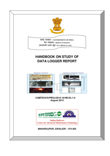
DL3 getting started.book Page 11 Monday, September 18, 2006 4:44 PMInstalling Software and Connecting the 34970A12 Install the IO Libraries Suite: Close all other applications on your PC, insert theAutomation-Ready CD with Agilent IO Libraries Suiteinto your CD-ROM drive, and follow the instructions onyour screen. If the IO Libraries Suite installation does not startautomatically, select Start Run (on the Windows Startmenu) and type drive :\autorun\auto.exe, where driveis your CD-ROM drive. After IO Libraries Suite has been successfully installed,you will see the IO Control (IO icon) in the taskbarnotification area on your PC screen as in Figure 1. (Thetaskbar notification area is where the clock is usuallydisplayed.)1 If you have difficulty with the installation, seeChapter 3, of the IO Libraries Suite Getting Started Guide,which you can display (in PDF format) by clicking the IOControl and choosing Documentation IO Libraries SuiteGetting Started. The Documentation menu also includesmanuals for Agilent interface hardware products that youhave installed.Figure 1Getting Started with BenchLink Data Logger 3IO Control icon in taskbar notification area11
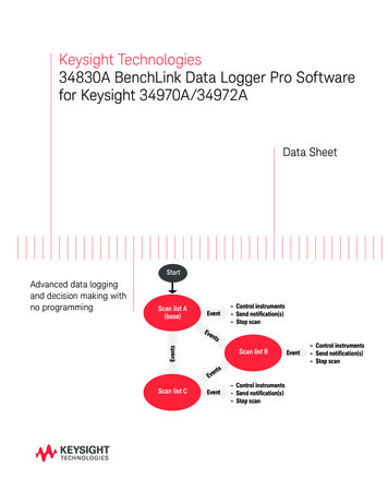
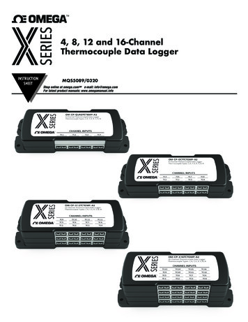
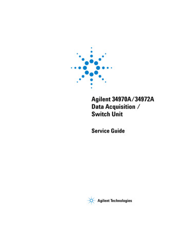
DL3 getting started.book Page 12 Monday, September 18, 2006 4:44 PM1Installing Software and Connecting the 34970AStep 2. Install the BenchLink Data Logger 3 SoftwareThe Agilent BenchLink Data Logger 3 Software is contained onthe 34825A product CD-ROM. The 34825A CD-ROM is includedwith every 34970A shipment.Installation ProcedureWindows 98, Windows SE, Windows NT 4.0 , Windows 2000,Windows XP:1 Insert the 34825A Product CD-ROM into your drive.2 From the product CD-ROM window that is displayed(following page), locate Agilent BenchLink Data LoggerSoftware in the Software menu.3 Click on Install and follow the instructions as prompted bythe installation utility.On-Line Help SystemThe BenchLink Data Logger 3 software is shipped with anextensive on-line help system to help you learn the features ofthe software as well as troubleshoot any problems that mightarise as you are using the software. As you are installing thesoftware, you will notice that the on-line help system isavailable in several languages.12Getting Started with BenchLink Data Logger 3
DL3 getting started.book Page 13 Monday, September 18, 2006 4:44 PMInstalling Software and Connecting the 34970AFigure 21Product CD ROM WindowGetting Started with BenchLink Data Logger 313
DL3 getting started.book Page 14 Monday, September 18, 2006 4:44 PM1Installing Software and Connecting the 34970AStep 3. Install Plug-In Modules into the 34970A MainframeRefer to the Agilent 34970A User’s Guide for informationon installing modules and connecting test wiring to themodules.14Getting Started with BenchLink Data Logger 3
DL3 getting started.book Page 15 Monday, September 18, 2006 4:44 PMInstalling Software and Connecting the 34970A1Step 4. Install Interface HardwareIf you received the Agilent IO Libraries Suite when youpurchased an instrument or an interface product (such as anAgilent GPIB card or USB/GPIB interface converter), it is timeto install the hardware now.Consult the documentation for your hardware product forinstallation instructions and specific hardware configuration(for example, setting Ethernet or GPIB addresses). Generalinstructions for hardware installation appear in the AgilentConnectivity Guide, which you can display (in PDF format) byclicking the IO Control and choosing Documentation Connectivity Guide. The Documentation menu also includesmanuals for Agilent interface hardware products that you haveinstalled.Getting Started with BenchLink Data Logger 315
DL3 getting started.book Page 16 Monday, September 18, 2006 4:44 PM1Installing Software and Connecting the 34970AThe Computer and Interface CableSince computers and operating systems are the subject of manybooks and periodicals, they are not discussed in this chapter. Inaddition to the computer and operating system, you will need aserial port (RS-232) or GPIB port (IEEE-488) and an interfacecable.Serial (RS-232)GPIB ntagesOften built into thecomputer; no additionalhardware is required.Cable length is limited to 45ft. (15 m). *Speed; faster data andcommand transfers.Cable length is limited to 60ft. (20 m). *Drivers usually included inthe operating system.Only one instrument ordevice can be connectedper serial port.Additional systemflexibility, multipleinstruments can beconnected to the sameGPIB port.Requires an expansion slotplug-in card in PC andassociated drivers.Cables readily availableand inexpensive. The34970A is shipped with aserial cable (if internalDMM is ordered)Cabling is susceptible tonoise, causing slow or lostcommunications. Varyingconnector pinouts andstyles.Direct Memory Transfersare possible.Requires special cable.Data transfers up to 85,000characters/sec.Data transfers up to750,000 characters/sec.* You can overcome these cable length limitations using special communications hardware. For example, you can use theAgilent E5810A LAN-to-GPIB Gateway interface or a serial modem.16Getting Started with BenchLink Data Logger 3
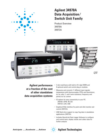
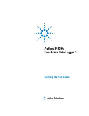
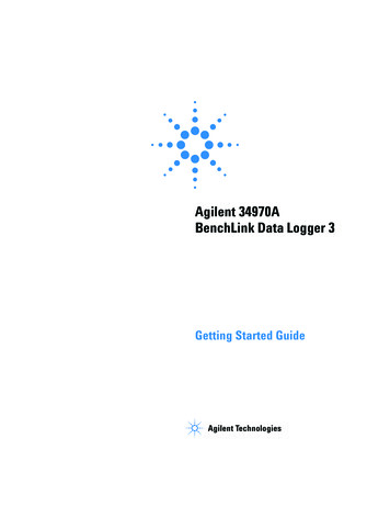
DL3 getting started.book Page 17 Monday, September 18, 2006 4:44 PMInstalling Software and Connecting the 34970A1Step 5. Connect the Interface Cable to the 34970ARS-232 ConnectorRS-232GP-IBGP-IB ConnectorFigure 334970A RS-232 and GPIB ConnectorsGetting Started with BenchLink Data Logger 317
DL3 getting started.book Page 18 Monday, September 18, 2006 4:44 PM1Installing Software and Connecting the 34970AStep 6. Apply Power to the 34970A1 Connect the power cord and turn on the instrument using theOn/Standby Switchlocated on the lower left side of thefront panel . The front-panel display will light up brieflywhile the instrument performs its power-on self-test. TheGPIB address is also displayed. The instrument initiallypowers up with all measurement channels turned off. Toreview the power-on display with all annunciators turned on,hold downShiftas you turn on the instrument. If the instrument doesnot turn on properly, refer to the Agilent 34970A User’sGuide.2 Perform a complete self-test. The complete self-test performsa more extensive set of tests than those performed atpower-on. Hold down Shift as you turn on the instrumentand hold down the key until you hear a long beep. Theself-test will begin when you release the key following thebeep. If the self-test fails, see the 34970A Service Guide forinstructions on returning the instrument to Agilent forservice.WA RN INGNote that this switch is Standby only. To disconnect the mains from theinstrument, remove the power cord.If the Instrument Does Not Turn OnUse the following steps to help solve problems you mightencounter when turning on the instrument. If you need morehelp, refer to the 34970A Service Guide for instructions onreturning the instrument to Agilent for service.1 Verify that there is ac power to the instrument. First, verifythat the power cord is firmly plugged into the powerreceptacle on the rear panel of the instrument. You shouldalso make sure that the power source you plugged the18Getting Started with BenchLink Data Logger 3
DL3 getting started.book Page 19 Monday, September 18, 2006 4:44 PMInstalling Software and Connecting the 34970A1instrument into is energized. Then, verify that the instrumentis turned on.2 Verify the power-line voltage setting. The line voltageis set to the proper value for your country when theinstrument is shipped from the factory. Change the voltagesetting if it is not correct. The settings are: 100, 120, 220, or240 Vac.NO TEFor 127 Vac operation, use the 120 Vac setting. For 230 Vac operation, usethe 220 Vac setting.Refer to the Agilent 34970 User’s Guide if you need to changethe line voltage setting.3 Verify that the power-line fuse is good. The instrument isshipped from the factory with a 500 mA fuse installed. This isthe correct fuse for all line voltages. See the Agilent 34970AUser’s Guide if you need to replace the power-line fuse. Toreplace the 500 mAT, 250 V fuse, order Agilent part number2110-0458.1Getting Started with BenchLink Data Logger 319
DL3 getting started.book Page 20 Monday, September 18, 2006 4:44 PM1Installing Software and Connecting the 34970AStep 7. Configure the 34970A Interface SettingsThe Front-Panel Menus at a GlanceSeveral of the front-panel keys guide you through menus toconfigure various parameters of the instrument (see the Agilent34970A User’s Guide). The following steps demonstrate themenu structure.1 Press the menu key. You are automatically guided to the firstlevel of the menu. Rotate the knob to view the other choiceson the first level of the menu.The menu will automatically timeout after about 20 secondsof inactivity. You will be returned to the operation inprogress prior to entering the menu.20Getting Started with BenchLink Data Logger 3
DL3 getting started.book Page 21 Monday, September 18, 2006 4:44 PMInstalling Software and Connecting the 34970A12 Press the same menu key again to move to the next item ofthe menu. Typically, this is where you choose parametervalues for the selected operation.3 Rotate the knob to view the choices on this level of the menu.When you reach the end of the list, rotate the knob in theopposite direction to view all of the other choices. Thecurrent selection is highlighted for emphasis. All otherchoices are dimmed.Getting Started with BenchLink Data Logger 321
DL3 getting started.book Page 22 Monday, September 18, 2006 4:44 PM1Installing Software and Connecting the 34970A4 Press the same menu key again to accept the change and exitthe menu. A brief confirmation message is displayed.NO TE22To review the current configuration of a specific menu, press the menu keyseveral times. A message NO CHANGES is displayed when you exit themenu.Getting Started with BenchLink Data Logger 3
DL3 getting started.book Page 23 Monday, September 18, 2006 4:44 PMInstalling Software and Connecting the 34970A1To Configure the Remote InterfaceThe instrument is shipped with both a GPIB (IEEE-488)interface and an RS-232 interface. Only one interface can beenabled at a time. The GPIB interface is selected when theinstrument is shipped from the factory.ShiftSto/RclGPIB Configuration1 Select the GPIB (HPIB) interface.InterfaceGPIB / 488Sto/RclInterface2 Use the knob to select the GPIB address. You can set theinstrument’s address to any value between 0 and 30. Thefactory setting is address “9”.ADDRE SS 09Sto/RclInterfaceNO TE3 Save the change and exit the menu.Your computer’s GPIB interface card has its own address. Be sure to avoidusing the computer’s address for any instrument on the interface bus.Agilent’s GPIB interface cards generally use address “21”.Getting Started with BenchLink Data Logger 323
DL3 getting started.book Page 24 Monday, September 18, 2006 4:44 PM1Installing Software and Connecting the 34970ARS-232 ConfigurationShiftSto/Rcl1 Rotate the knob to select the RS-232 interface.InterfaceRS-232Sto/RclInterface2 Rotate the knob to select the baud rate. Select one of the following: 9600, 19200, 38400, 57600(factory setting), or 115200 baud.19200 BAUDNO TESto/RclInterfaceThe Data Logger 3 software does not support the 1200, 2400, or 4800baud rate.3 Rotate the knob to select the parity and number of data bits. Select one of the following: None (8 data bits, factorysetting), Even (7 data bits), or Odd (7 data bits). When youset the parity, you are also indirectly setting the number ofdata bits.EVEN, 7 BITSSto/RclInterface4 Rotate the knob to select the flow control method. Select one of the following: None (no flow control),RTS/CTS, DTR/DSR, XON/XOFF (factory setting), orModem.FLOW DTR/DSRSto/RclInterface245 Save the changes and exit the menu.Getting Started with BenchLink Data Logger 3
DL3 getting started.book Page 25 Monday, September 18, 2006 4:44 PMInstalling Software and Connecting the 34970A1Step 8. Run the Agilent Connection Expert to Verify the I/OConfiguration1 Run Connection Expert. If the Connection Expert utility doesnot run automatically at this time, click the IO Control (IOicon in the Windows notification area) and then click AgilentConnection Expert.2 Change the I/O configuration, if necessary. ConnectionExpert will automatically detect most interfaces andinstruments, and will assign names and other defaultconfiguration settings. If you want to change theseparameters, you can do so in the Connection Expert window. Select the instrument or interface in the explorer pane inthe center of the Connection Expert window. The properties of the selected item appear in theproperties pane on the right. When you right-click on anitem in the explorer pane, you see a shortcut menu ofactions that you may take on that item. These actions arealso available from the menus at the topof the Connection Expert window. The most commonactions are also listed in the Connection Expert’s taskguide (the left pane of the window). You may also add instruments or interfaces manuallyto your test system configuration if Connection Expertdoes not automatically detect the hardware (for example,if it is connected via Ethernet or via serial port). Refer to the Agilent IO Libraries Suite Online Help formore information on Connection Expert and onconfiguration changes.3 Test the instrument connections.Getting Started with BenchLink Data Logger 325
DL3 getting started.book Page 26 Monday, September 18, 2006 4:44 PM1Installing Software and Connecting the 34970A Connection Expert will automatically send anidentification query (*IDN?) to any instrument that has itsauto-identify property set to Yes. (See the Agilent IOLibraries Suite Online Help if you want to turn thisfunction off.) When you see a green check mark on the icon representingan instrument, this means that the instrument hasresponded as expected. (Note that some instruments donot support the *IDN? query and will not respondappropriately.) The instrument’s identificationinformation is displayed in the properties pane on theright side of the Connection Expert window. You can explicitly test the connections to yourinstruments, and exercise more of their functionality, byselecting Send commands to this instrument in the taskguide or shortcut menu. This starts the Interactive IOutility, which allows you to send commands to yourinstruments and see their responses. Note that somecommands (such as *TST?, instrument self-test) may takelonger than Interactive IO’s default timeout; you canmodify the timeout in the Interactive IO windowby selecting Interact Options.26Getting Started with BenchLink Data Logger 3
DL3 getting started.book Page 27 Monday, September 18, 2006 4:44 PMInstalling Software and Connecting the 34970A1Step 9. Run the BenchLink Data Logger 3 SoftwareYou can now run the BenchLink Data Logger 3 software.Chapter 2 contains a step-by-step tutorial showing you how tooperate the BenchLink Data Logger 3 software.Getting Started with BenchLink Data Logger 327
DL3 getting started.book Page 28 Monday, September 18, 2006 4:44 PM128Installing Software and Connecting the 34970AGetting Started with BenchLink Data Logger 3
DL3 getting started.book Page 29 Monday, September 18, 2006 4:44 PMAgilent 34970A BenchLink Data Logger 3Getting Started Guide1Getting Started with BenchLinkData Logger 3Getting Started Tutorial 30Step 1. Create a New Configuration 31Step 2. Configure 34970As 33Step 3. Configure Channels 36Step 4. Set Up Scan Control and Data Control 41Step 5. Start the Scan 43Step 6. View Data Graph 44Step 7. Customize the Graph 45Step 8. Stop the Scan 46Step 9. Export the Data 48Agilent Technologies29
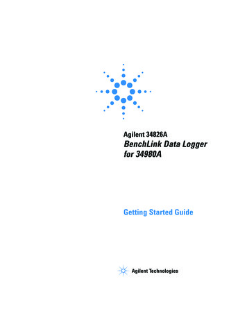
DL3 getting started.book Page 30 Monday, September 18, 2006 4:44 PM1Getting Started with BenchLink Data Logger 3Getting Started TutorialThis getting started tutorial introduces you to the BenchLinkData Logger 3 and shows you how to: Connect to one or more 34970As Set up a simple channel configuration Scan channels and measure some data View the data in graphical form Export the data to a Microsoft Excel-compatible spreadsheet Save the configurationTo start Benchlink Data Logger 3, click this shortcut on yourdesktop:The graphic below shows the menus, status area and tabs in theuser interface. The Data Logger 3 online help (available bypressing F1 or clicking the Help menu) describes the userinterface in detail.MenusStatus AreaTabs30Getting Started with BenchLink Data Logger 3
DL3 getting started.book Page 31 Monday, September 18, 2006 4:44 PMGetting Started with BenchLink Data Logger 31Step 1. Create a New ConfigurationIn this step we will create a new configuration. A configurationcontains all of the instrument settings, scan settings and graphsettings that you have configured in the Data Logger 3application. Following a scan, each scan datalog is alsoassociated with the configuration. A configuration events log isalso associated with each configuration.NO TEFor purposes of example, this tutorial assumes you have a 34901A or34902A multiplexer module installed in a 34970A. Although you can use upto four 34970As in a configuration, this tutorial uses only one 34970A. Youshould not have any channels connected to external equipment or signalsources for this tutorial.1 Click Configuration New. to create a new configuration.2 You will be prompted to enter a new configuration name andcomments. For this tutorial, enter the information shownbelow and click OK.Getting Started with BenchLink Data Logger 331
DL3 getting started.book Page 32 Monday, September 18, 2006 4:44 PM1Getting Started with BenchLink Data Logger 3The configuration name appears under Configuration: in thestatus area of the application window. For example:NO TE32Notice the unlocked padlock icon to the right of the configuration name.This indicates the configuration does not yet have a datalog and iseditable. Once a scan has occurred and a datalog exists for theconfiguration, the padlock will be shown as locked. To alter a lockedconfiguration, you must either delete the associated datalog(s) or copyand rename the configuration.Getting Started with BenchLink Data Logger 3
DL3 getting started.book Page 33 Monday, September 18, 2006 4:44 PMGetting Started with BenchLink Data Logger 31Step 2. Configure 34970AsIn this step you will identify which 34970A(s) to use in theconfiguration.Data Logger 3 can be used in either of these two modes: Connected to 34970A (Connected Mode) — Select this modeif you have one or more 34970As connected via interface toyour computer. Connected Mode is the recommended modeto use whenever possible. This is because, in ConnectedMode, the software automatically determines the 34970Aaddress and installed modules. Not connected to 34970A (Not Connected Mode) —Thismode allows you to develop scanning configurations“off-line” without being connected to any 34970As. Forexample, you can develop a configuration in your office andlater connect to 34970As on the production floor.NO TEThis tutorial uses the Connected Mode and assumes your PC is connectedvia interface to at least one 34970A and communication has beenestablished. If you have not done so, you can use the Agilent ConnectionExpert to automatically configure interfaces and check 34970Acommunications. This utility is on the Automation-Ready CD ROMincluded with the 34970A.1 On the Configure 34970As tab, click Connected to 34970A.Notice on the Configure 34970As tab, the configurationsteps (1 through 4) are shown in bold lettering from left toright.NO TEYou can access the help for the selected tab by clicking the F1 key.2 Click the Add 34970s. button.3 Make sure the 34970s to be added are powered-on andconnected to the PC via an interface
The Agilent BenchLink Data Logger 3 Software is contained on the 34825A product CD-ROM. The 34825A CD-ROM is included with every 34970A shipment. Installation Procedure Windows 98, Windows SE, Windows NT 4.0 , Windows 2000, Windows XP: 1 Insert the 34825A Product CD-ROM into your drive. 2 From the product CD-ROM window that is displayed .