Transcription
GUIDELINES AND STANDARDSMultimodality Imaging of Diseases of the ThoracicAorta in Adults: From the American Societyof Echocardiography and the European Associationof Cardiovascular ImagingEndorsed by the Society of Cardiovascular Computed Tomographyand Society for Cardiovascular Magnetic ResonanceSteven A. Goldstein, MD, Co-Chair, Arturo Evangelista, MD, FESC, Co-Chair, Suhny Abbara, MD,Andrew Arai, MD, Federico M. Asch, MD, FASE, Luigi P. Badano, MD, PhD, FESC, Michael A. Bolen, MD,Heidi M. Connolly, MD, Hug Cu ellar-Cal abria, MD, Martin Czerny, MD, Richard B. Devereux, MD,Raimund A. Erbel, MD, FASE, FESC, Rossella Fattori, MD, Eric M. Isselbacher, MD, Joseph M. Lindsay, MD,Marti McCulloch, MBA, RDCS, FASE, Hector I. Michelena, MD, FASE, Christoph A. Nienaber, MD, FESC,Jae K. Oh, MD, FASE, Mauro Pepi, MD, FESC, Allen J. Taylor, MD, Jonathan W. Weinsaft, MD,Jose Luis Zamorano, MD, FESC, FASE, Contributing Editors: Harry Dietz, MD, Kim Eagle, MD,John Elefteriades, MD, Guillaume Jondeau, MD, PhD, FESC, Herv e Rousseau, MD, PhD,and Marc Schepens, MD, Washington, District of Columbia; Barcelona and Madrid, Spain; Dallas and Houston,Texas; Bethesda and Baltimore, Maryland; Padua, Pesaro, and Milan, Italy; Cleveland, Ohio; Rochester, Minnesota;Zurich, Switzerland; New York, New York; Essen and Rostock, Germany; Boston, Massachusetts; Ann Arbor,Michigan; New Haven, Connecticut; Paris and Toulouse, France; and Brugge, Belgium(J Am Soc Echocardiogr 2015;28:119-82.)TABLE OF CONTENTSPreamble 121I. Anatomy and Physiology of the Aorta 121A. The Normal Aorta and Reference Values 1211. Normal Aortic Dimensions 122From the Medstar Heart Institute at the Washington Hospital Center, Washington,District of Columbia (S.A.G., F.M.A., J.M.L., A.J.T.); Vall d’Hebron UniversityHospital, Barcelona, Spain (A.E., H.C.-C.); the University of Texas SouthwesternMedical Center, Dallas, Texas (S.A.); the National Institutes of Health, Bethesda,Maryland (A.A.); the University of Padua, Padua, Italy (L.P.B.); Cleveland Clinic,Cleveland, Ohio (M.A.B.); Mayo Clinic, Rochester, Minnesota (H.M.C., H.I.M.,J.K.O.); the University Hospital Zurich, Zurich, Switzerland (M.C.); Weill CornellMedical College, New York, New York (R.B.D., J.W.W.); West-German HeartCenter, University Duisburg-Essen, Essen, Germany (R.A.E.); San SalvatoreHospital, Pesaro, Italy (R.F.); Massachusetts General Hospital, Boston,Massachusetts (E.M.I.); the Methodist DeBakey Heart & Vascular Center,Houston, Texas; the University of Rostock, Rostock, Germany (C.A.N.); Centro n yCardiologico Monzino, IRCCS, Milan, Italy (M.P.); University Hospital RamoCajal, Madrid, Spain (J.L.Z.); Johns Hopkins University School of Medicine,Baltimore, Maryland (H.D.); the University of Michigan, Ann Arbor, Michigan(K.E.); Yale University School of Medicine, New Haven, Connecticut (J.E.);Hopital Bichat, Paris, France (G.J.); Hopital de Rangueil, Toulouse, France(H.R.); and AZ St Jan Brugge, Brugge, Belgium (M.S.).The following authors reported no actual or potential conflicts of interest in relation to this document: Federico M. Asch, MD, FASE, Michael A. Bolen, MD, Heidi llar-Cala bria, MD, Martin Czerny, MD, Richard B. DeM. Connolly, MD, Hug Cuevereux, MD Harry Dietz, MD, Raimund A. Erbel, MD, FASE, FESC, Arturo Evangelista, MD, FESC, Rossella Fattori, MD, Steven A. Goldstein, MD, GuillaumeJondeau, MD, PhD, FESC, Eric M. Isselbacher, MD, Joseph M. Lindsay, MD,Marti McCulloch, MBA, RDCS, FASE, Hector I. Michelena, MD, FASE, ChristophNienaber, MD, FESC, Mauro Pepi, MD, FESC, Marc Schepens, MD, Allen J.B. How to Measure the Aorta 1241. Interface, Definitions, and Timingments 124ofAorticMeasure-Taylor, MD, and Jose Luis Zamorano, MD, FESC, FASE. The following authorsreported relationships with one or more commercial interests: Suhny Abbara,MD, serves as a consultant for Perceptive Informatics. Andrew Arai, MD, receives research support from Siemens. Luigi P. Badano, MD, PhD, FESC, hasreceived software and equipment from GE Healthcare, Siemens, and TomTecfor research and testing purposes and is on the speakers’ bureau of GE Healthcare. Kim Eagle, MD, received a research grant from GORE. John Elefteriades,MD, has a book published by CardioText and is a principal investigator on agrant and clinical trial from Medtronic. Jae K. Oh, MD, received a research grant Rousseau, MD,from Toshiba and core laboratory support from Medtronic. Herveserves as a consultant for GORE, Medtronic, and Bolton. Jonathan W. Weinsaft,MD, received a research grant from Lantheus Medical Imaging.Attention ASE Members:The ASE has gone green! Visit www.aseuniversity.org to earn free continuingmedical education credit through an online activity related to this article.Certificates are available for immediate access upon successful completionof the activity. Nonmembers will need to join the ASE to access this greatmember benefit!Reprint requests: American Society of Echocardiography, 2100 Gateway CentreBoulevard, Suite 310, Morrisville, NC 27560 (E-mail: ase@asecho.org).0894-7317/ 36.00Copyright 2015 by the American Society of 2014.11.015119
120 Goldstein et alAbbreviationsAAS Acute aortic syndromeAR Aortic regurgitationASE American Society ofEchocardiographyBAI Blunt aortic injuryBSA Body surface areaCT Computed tomographyCTA Computedtomographic aortographyCXR Chest x-rayEACVI EuropeanAssociation of CardiovascularImagingEAU Epiaortic ultrasoundGCA Giant-cell (temporal)arteritisICM Iodinated contrastmediaIMH Intramural hematomaIRAD International Registryof Acute Aortic DissectionMDCT Multidetectorcomputed tomographyMIP Maximum-intensityprojectionMR Magnetic resonanceMRI Magnetic resonanceimagingPWV Pulsewave velocitySTJ Sinotubular junctionTA Takayasu arteritisTEE TransesophagealechocardiographyTEVAR Transthoracicendovascular aortic repair3D Three-dimensionalTTE Transthoracicechocardiography2D Two-dimensionalULP Ulcerlike projectionJournal of the American Society of EchocardiographyFebruary 20152. Geometry of DifferentAortic Segments:Impact on Measurements 126a. AorticAnnulus 126b. Sinuses of Valsalvaand STJ 126c. Ascending Aorta andMore Distal Segments 126C. Aortic Physiology andFunction 1271. Local Indices of AorticFunction 1272. Regional Indices ofAortic Stiffness: Pulsewave Velocity(PWV)128II. Imaging Techniques 129A. Chest X-Ray (CXR)129B. TTE129C. TEE1301. ImagingoftheAorta 130D. Three-Dimensional Echocardiography 131E. Intravascular Ultrasound(IVUS) 1311. Limitations 131F. CT 1311. Methodology132a. CTA 132i. NoncontrastCTbefore Aortography 133ii. Electrocardiographically GatedCTA 133iii. ThoracoabdominalCT after Aortography 133iv. ExposuretoIonizing Radiation 134v. Measurements 134G. MRI1351. Black-BloodSequences 1352. CineMRISequences 1353. Flow Mapping 1354. Contrast-Enhanced MRAngiography(MRA) 1355. Artifacts 136H. InvasiveAortog-raphy 136I. Comparison of Imaging TechniquesIII. Acute Aortic Syndromes 138A. Introduction 138B. Aortic Dissection1381. Classification of Aortic Dissection2. Echocardiography (TTE and TEE)137138139a. Echocardiographic Findings 140b. Detection of Complications 141c. Limitations of TEE1413. CT 1414. MRI of Aortic Dissection1435. Imaging Algorithm 1446. Use of TEE to Guide Surgery for Type A Aortic Dissection1447. Use of Imaging Procedures to Guide Endovascular Therapy 1468. Serial Follow-Up of Aortic Dissection (Choice of Tests) 1479. Predictors of Complications by Imaging Techniques148a. Maximum Aortic Diameter 148b. Patent False Lumen 148c. Partial False Luminal Thrombosis149d. Entry Tear Size 149e. True Luminal Compression14910. Follow-Up Strategy 149C. IMH 1491. Introduction 1492. Imaging Hallmarks and Features1493. Imaging Algorithm 1514. Serial Follow-Up of IMH (Choice of Tests) 1515. Predictors of Complications 151D. PAU 1511. Introduction 1512. Imaging Features1513. Imaging Modalities 152a. CT 152b. MRI152c. TEE152d. Aortography 1524. Imaging Algorithm 1535. Serial Follow-Up of PAU (Choice of Tests) 153IV. Thoracic Aortic Aneurysm 153A. Definitions and Terminology 153B. Classification of Aneurysms 154C. Morphology 154D. Serial Follow-Up of Aortic Aneurysms (Choice of Tests) 1541. Algorithm for Follow-Up 155E. Use of TEE to Guide Surgery for TAAs 155F. Specific Conditions 1561. Marfan Syndrome 156a. Aortic Imaging in Unoperated Patients with Marfan Syndrome 156b. Postoperative Aortic Imaging in Marfan Syndrome 157c. Postdissection Aortic Imaging in Marfan Syndrome 157d. Family Screening1572. Other Genetic Diseases of the Aorta in Adults157a. Turner Syndrome 157b. Loeys-Dietz Syndrome 157c. Familial TAAs 157d. Ehlers-Danlos Syndrome 1573. BAV-Related Aortopathy 157a. Bicuspid Valve–Related Aortopathy 157b. Imaging of the Aorta in Patients with Unoperated BAVs 158c. Follow-Up Imaging of the Aorta in Patients with UnoperatedBAVs 158d. Postoperative Aortic Imaging in Patients with BAV-RelatedAortopathy 158e. Family Screening159V. Traumatic Injury to the Thoracic Aorta 159A. Pathology 159B. Imaging Modalities 1601. CXR1602. Aortography 1603. CT 160
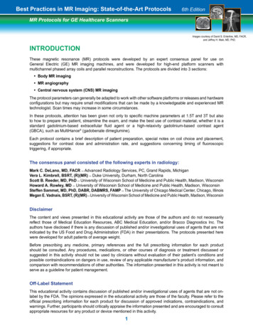
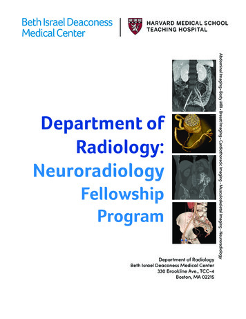
Goldstein et al 121Journal of the American Society of EchocardiographyVolume 28 Number 24. TEE1615. IVUS 1616. MRI162C. Imaging Algorithm 162D. Imaging in Endovascular Repair 162VI. Aortic Coarctation 162A. Aortic Imaging in Patients with Unoperated Aortic Coarctation 163B. Postoperative Aortic Imaging in Coarctation 164VII. Atherosclerosis 164A. Plaque Morphology and Classification 164B. Imaging Modalities 1651. Echocardiography 1652. Epiaortic Ultrasound (EAU) 1653. CT 1664. MRI166C. Imaging Algorithm 166D. Serial Follow-Up of Atherosclerosis (Choice of Tests)167VIII.Aortitis 167A. Mycotic Aneurysms of the Aorta 167B. Noninfectious Aortitis 168IX. Postsurgical Imaging of the Aortic Root and Aorta 169A. What the Imager Needs to Know 169B. Common Aortic Surgical Techniques 1691. Interposition Technique 1692. Inclusion Technique 1693. Composite Grafts 1694. Aortic Arch Grafts 1695. Elephant Trunk Procedure1696. Cabrol Shunt Procedure1707. Technical Adjuncts 170C. Normal Postoperative Features170D. Complications after Aortic Repair 1701. Pseudoaneurysm 1702. False Luminal Dilatation 1703. Involvement of Aortic Branches 1714. Infection 171E. Recommendations for Serial Imaging Techniques andSchedules 171X. Summary 171Notice and Disclaimer171References 171PREAMBLEAortic pathologies are numerous, presenting manifestations are varied,and aortic diseases present to many clinical services, including primaryphysicians, emergency department physicians, cardiologists, cardiac surgeons, vascular surgeons, echocardiographers, radiologists, computedtomography (CT) and magnetic resonance (MR) imaging (MRI) imagers, and intensivists. Many aortic diseases manifest emergently andare potentially catastrophic unless suspected and detected promptlyand accurately. Optimal management of these conditions depends onthe reported findings from a handful of imaging modalities, includingechocardiography, CT, MRI, and to a lesser extent invasive aortography.In the past decade, there have been remarkable advances in noninvasive imaging of aortic diseases. This document is intended to provide acomprehensive review of the applications of these noninvasive imagingmodalities to aortic disease. Emphasis is on the advantages and disadvantages of each modality when applied to each of the various aorticdiseases. Presently, there is a lack of consensus on the relative role(comparative effectiveness) of these imaging modalities. An attempthas been made to determine first-line and second-line choices forsome of these specific conditions. Importantly, we have emphasizedthe need for uniform terminology and measurement techniques.Whenever possible, these recommendations are evidence based,following a critical review of the literature. In some instances, the recommendations reflect a consensus of the expert writing group and include‘‘vetting’’ by additional experts from the supporting imaging societies.Because of the importance of prompt recognition to their successfultreatment, this review emphasizes acute aortic syndromes (AAS), suchas aortic dissection and its variants (e.g., intramural hematoma [IMH]),rupture of ascending aortic aneurysm, aortic trauma, and penetratingulcer. Other entities, such as Takayasu aortitis (TA), giant-cell (temporal)arteritis (GCA), and mycotic aneurysm, are discussed briefly. Less common aortic diseases such as aortic tumors (because of their rarity) andcongenital anomalies of the coronary arteries, aortic arch, and sinus ofValsalva aneurysms are not addressed. Several other topics are alsobeyond the scope of this review, including the important and emergingrole of genetics in the evaluation and management of aortic diseases.Moreover, this document is not intended to replace or extend the recommendations of prior excellent guidelines in decision making andmanagement for these conditions.1To summarize, the focus of this document is the fundamental roleof the major noninvasive imaging techniques. In addition to clinicalacumen and suspicion, knowledge of these imaging modalities iscrucial for the assessment and management of the often lifethreatening diseases of the aorta.I. ANATOMY AND PHYSIOLOGY OF THE AORTAA. The Normal Aorta and Reference ValuesThe aorta is the largest and strongest artery in the body; its wall consistsof three layers: the thin inner layer or intima, a thick middle layer or media, and a rather thin outer layer, or adventitia. The endothelium-linedaortic intima is a thin, delicate layer and is easily traumatized. The mediais composed of smooth muscle cells and multiple layers of elasticlaminae that provide not only tensile strength but also distensibilityand elasticity, properties vital to the aorta’s circulatory role. The adventitia contains mainly collagen as well as the vasa vasorum, whichnourish the outer half of the aortic wall and a major part of the media.The elastic properties of the aorta are important to its normal function. The elasticity of the wall allows the aorta to accept the pulsatileoutput of the left ventricle in systole and to modulate continuedforward flow during diastole. With aging the medial elastic fibersundergo thinning and fragmentation. The ordinary concentricarrangement of the laminae is disturbed. These degenerative changesare accompanied by increases in collagen and ground substance. Theloss of elasticity and compliance of the aortic wall contributes to theincrease in pulse pressure commonly seen in the elderly and maybe accompanied by progressive dilatation of the aorta.A geometrically complex organ, the aorta begins at thebulb-shaped root (level 1 in Figure 1) and then courses through thechest and abdomen in a candy cane–shaped configuration, with a variable orientation to the long axis of the body, until it terminates in theiliac bifurcation. The aorta consists of five main anatomic segments:the aortic root, the tubular portion of the ascending aorta, the aorticarch, the descending thoracic aorta, and the abdominal aorta. Themost proximal part of the ascending aorta, the aortic root (segmentI in Figure 1), includes the aortic valve annulus, aortic valve cusps,
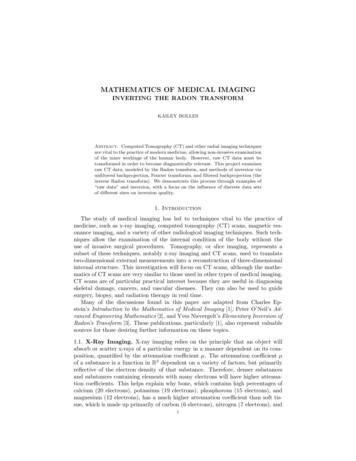
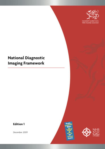
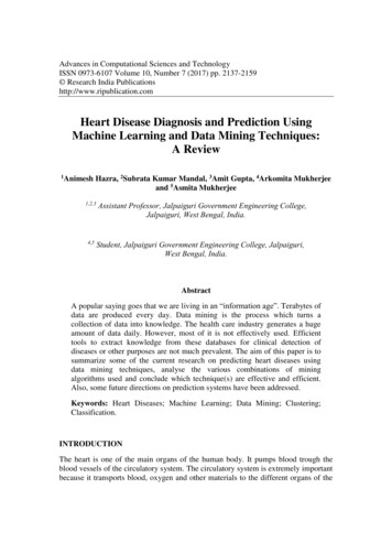
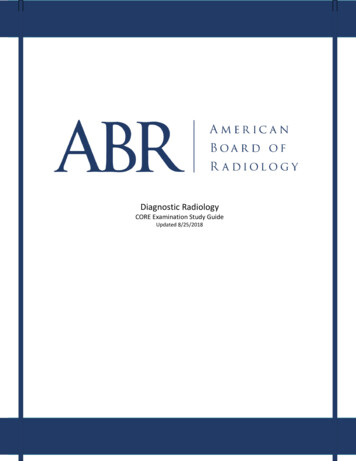
122 Goldstein et alJournal of the American Society of EchocardiographyFebruary 2015Figure 2 Transthoracic echocardiogram in the parasternallong-axis view (zoomed on aortic root and ascending aorta) illustrating measurement of the aortic root diameter at sinus ofValsalva level at end-diastole using the leading edge–to–leading-edge method. asc Ao, Ascending aorta; LVOT, left ventricularoutflow tract.to the ostia of the renal arteries, and the distal part (segment Vb),from the renal arteries to the iliac bifurcation.Figure 1 CT reconstruction of a normal aorta illustrating itssegmentation as follows: segment I aortic root; segment II tubular ascending aorta (subdivided into IIa [STJ to the pulmonary artery level] and IIb [from the pulmonary artery level to thebrachiocephalic artery]); segment III aortic arch; segmentIV descending thoracic aorta (subdivided into IVa [from theleft subclavian artery to the level of the pulmonary artery] andIVb [from the level of the pulmonary artery to the diaphragm]);and segment V abdominal aorta (subdivided into Va [upperabdominal aorta from the diaphragm to the renal arteries] andVb [from the renal arteries to the iliac bifurcation]).coronary ostia, and sinuses of Valsalva. Distally the root joins thetubular portion of the ascending aorta (segment II) at an easily recognized landmark termed the sinotubular junction (STJ). The tubularportion of the ascending aorta extends from the STJ to the origin ofthe brachiocephalic artery. This relatively long segment is subdividedinto segment IIa, which extends from the STJ to the pulmonary arterylevel, and segment IIb, from the pulmonary artery level to the brachiocephalic artery. The aortic arch (segment III) extends from the brachiocephalic artery to the left subclavian artery. The descendingthoracic aorta (segment IV) may be subdivided into the proximalpart (segment IVa), which extends from the left subclavian artery tothe level of the pulmonary artery, and the distal part (segment IVb),which extends from the level of the pulmonary artery to the diaphragm. The abdominal aorta (segment V) may be subdivided intothe proximal part (segment Va), which extends from the diaphragm1. Normal Aortic Dimensions. Because of the ease with which itcan be visualized and its clinical relevance,2,3 the aortic root is thesegment for which the greatest amount of data are available.Several large studies have reported normal aortic root diameters inthe parasternal long-axis view by two-dimensional (2D) transthoracicechocardiography (TTE).4-10 Measurement of the aortic rootdiameter should be made perpendicular to the axis of the proximalaorta, recorded from several slightly differently oriented long-axisviews. The standard measurement is taken as the largest diameterfrom the right coronary sinus of Valsalva to the posterior (usually noncoronary) sinus. Most studies report aortic root diameter measurements at end-diastole using the leading edge–to–leading edgetechnique (Figure 2).In adults, aortic dimensions are strongly positively correlated withage5-8,10,11 and body size.4-6,8,10,11 They are larger in men than inwomen of the same age and body size.6,12,13 Although in severalreports, aortic diameters have been normalized to body surfacearea (BSA),10,13,14 this approach has not been entirely satisfactorybecause it is systematically lower in smaller than in larger normaladults. Fortunately, among children, the regression line of aorticdiameter and height (rather than BSA) has a near-zero intercept, sothat normalization to height has proved to be a simple and accuratealternative in growing children.15 Benchmark values from whichthe guidelines have been taken1,16 come from the work ofRoman et al.,9 who reported normal root dimensions for three agegroups (Figure 3).The upper limit of normal aortic diameter has been defined as 2SDs greater than the mean predicted diameter. The Z score (the number of SDs above or below the predicted mean normal diameter) is auseful way to quantify aortic dilatation. Among normal subjects,95.4% have Z scores between 2 and 2. Therefore, an aortic diameter can be considered dilated when the Z score is 2. Using the Zscore allows comparison of a given patient’s aortic size at differenttime points, accounting for the effects of advancing age and increasing
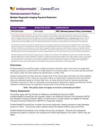
Goldstein et al 123Journal of the American Society of EchocardiographyVolume 28 Number 2Figure 3 Aortic root diameter (vertical axis) in relation to BSA (horizontal axis) in apparently normal individuals aged 1 to 15 (left panel,blue), 20 to 39 (center panel, green), and 40 (right panel, pink) years. For example, an individual between the ages of 20 and 39 years(center panel, green) who has a BSA of 2.0 m2 (vertical green line) has a normal root diameter range (2 SDs) between 2.75 and 3.65 cm,as indicated by the intersections of the two horizontal green lines with the green-shaded parallelogram.Table 1 Normal aortic root diameter by age for men with BSAof 2.0 m2Table 2 Normal aortic root diameter by age for women withBSA of 1.7 m2Age (y)Age (y)15–2930–3940–4950–5960–69 70Mean normal (cm)3.33.43.53.63.73.8Upper limit of normal(cm) (95% 0–69 70Mean normal (cm)2.93.03.23.23.33.4Upper limit of normal(cm)3.33.43.63.63.73.9Add 0.5 mm per 0.1 m2 BSA above 2.0 m2 or subtract 0.5 mm per0.1 m2 BSA below 2.0 m2.6CI, Confidence interval.Add 0.5 mm per 0.1 m2 BSA above 1.7 m2 or subtract 0.5 mm per0.1 m2 BSA below 1.7 m2.6body size, thus distinguishing normal from pathologic growth. The Zscore is therefore particularly useful for evaluating growing children.It should be mentioned that aortic root dimensions may beincreased by the hemodynamic effects of both endurance andstrength exercise training in competitive athletes.17-19 This aorticroot enlargement appears to be greater at the sinuses of Valsalvathan at the aortic annulus or STJ. However, it should beemphasized that the effects of exercise training on aortic diametersare relatively small and that marked enlargement should suggest apathologic process.17,18Recently, making use of a database consisting of a multiethnic population of 1,207 apparently normal adolescents and adults 15 yearsof age, investigators devised equations to predict mean normal aorticroot diameter and its upper limit by age, body size (BSA or height),and gender6 (Table 1 for men and Table 2 for women). These equations have been used graphically to depict the upper limits of the 95%confidence interval for normal aortic root diameter using surfaces todepict the interacting effects of age and body size (see Figure 4 formen and Figure 5 for women).A noncontrast gated cardiac computed tomographic study,20including 4,039 adult patients, showed age, BSA, gender, and hypertension to be directly associated with thoracic aortic diametersperpendicular to the long axis of the aorta. These associations areconcordant with those from echocardiographic studies. In anotherrecent large study using similar methodology, the mean value of thediameters of the ascending aorta was 1.8 6 0.2 cm/m2 and of the descending thoracic aorta was 1.4 6 0.2 cm/m2, with the upper limits ofnormal being 2.1 and 1.8 cm/m2, respectively.21 However, more accurate normal values of thoracic aortic diameters may be obtained byanatomically correct double-oblique short-axis images using electrocardiographically gated multidetector CT or by MRI of axially oriented aortic segments. The upper limits of normal are 3.7 cm forthe aortic root at the sinuses, 3.6 cm for the ascending aorta and2.5 cm for the descending thoracic aorta by CT,8 and 2.5 cm forthe descending thoracic aorta and 2.0 cm for the upper abdominalaorta by MRI.22 As with echocardiography, aortic root and ascendingaortic diameters increase significantly with age and BSA on CT andMRI. Aortic root diameters increase 0.9 mm per decade in menand 0.7 mm per decade in women.4The establishment of normative values and reference ranges, taking into account aging and gender, is of great importance for diagnosis, prognosis, serial monitoring, and determining the optimaltiming for surgical intervention. Normal values and proximal aortic diameters have been reported using different imaging techniques, fromthe pioneer studies based on M-mode and 2D echocardiography9,10to more recent studies obtained using CT7,8,20,23-25 and MRI.5,26Despite differences in image acquisition methods, temporal andspatial resolution, and signal-to-noise ratios, CT, MRI, TTE, and transesophageal echocardiography (TEE) have evolved as near equal standards for assessing aortic root size. Each of these modalities has
124 Goldstein et alJournal of the American Society of EchocardiographyFebruary 2015Figure 4 Surfaces representing aortic diameters at a 1.96 Zscore (95% confidence interval) above the predicted mean forage and BSA in male subjects 15 years of age. (Adaptedfrom Devereux et al.6)Figure 5 Surfaces representing aortic diameters 1.96 Z score(95% confidence interval) above the predicted mean value ofaortic diameter for age and BSA in female subjects 15 yearsof age. (Adapted from Devereux et al.6)advantages and disadvantages, which have been discussed. It shouldbe emphasized that normal aortic diameters vary systematically byage, gender, and body size, and reference values indexed to those parameters have been provided. Last, it is critically important to emphasize not only methodologic variance but also inter- and intraobservervariability. In several studies, variability of measurement of proximalaortic diameters ranges from 1.6 to 5 mm.8,23,24,27,28 Given thisdegree of variability, apparent small changes in proximal aorticdiameters on serial computed tomographic examinations may bewithin the range of measurement error. Accordingly, for all imagingtechniques, we recommend that changes of #3 mm byelectrocardiographically gated CT and #5 mm withoutelectrocardiographic gating be viewed with caution and skepticism.clinical and epidemiologic studies10,13 that have reported normallimits for individuals of differing body size and age, and thesenormal limits have been incorporated into multiple guidelines forimaging in adults (Figures 4 and 5).1,9,16 As a consequence, muchof the available data on normal aortic root size as well as on theprevalence and prognostic significance of aortic dilatation in adultshave emerged from echocardiography.6,10,13Societal guidelines for measurement by CT or MRI are notcurrently available. Consequently, uniformity in measurementmethods is lacking. Many research and clinical studies using these modalities have reported aortic measurements made from inner edge toinner edge on electrocardiographically gated or nongated images. The2010 guidelines for the diagnosis and management of thoracic aorticdisease took the opposite approach, recommending measurement ofaortic diameter between external surfaces to avoid confounding byintraaortic thrombus or atheroma, as is commonly found in theabdominal but not in the ascending aorta.1 Furthermore, there is nostandardized ‘‘trigger time’’ (end-systole vs end-diastole) for imageacquisition. Thus, the use of multiple imaging modalities such asCT, MRI, and 2D and three-dimensional (3D) echocardiographyhas led to nonuniformity in measurement techniques. Moreover,there is currently no standardized approach for reconciling aorticmeasurements across imaging modalities (echocardiography, CT,MRI, aortography) by trigger time (end-systole vs end-diastole) orby edge selection (leading edge, inner-inner, outer-outer). This writingcommittee had hoped to recommend a uniform and consistent measurement technique to minimize differences among these various imaging modalities. However, after much consideration, the grouprecommends that echocardiographic measurements continue to bemade in the standard fashion from leading edge to leading edge, atend-diastole, and perpendicular to the long axis of the aorta. Theadvantages of end-diastolic measurements include greater reproducibility (because aortic pressure is most stable in late diastole) and theease of identification of end-diastole by the onset of the QRSB. How to Measure the AortaAccurate and reproducible measurements of aortic dimensions arenecessary for the detection and classification of aortic disease andfor guiding therapeutic decisions. Modern imaging modalities enableone to make measurements far more accurately than did invasivecontrast angiography, the only tool originally available.Echocardiography, CT, and MRI each has particular strengths andlimitations but can be adapted for the acquisition of views that allowmeasurement of the diameter or cross-sectional area of different segments of the aorta (Figure 1).1. Interface, Definitions, and Timing of AorticMeasurements. The American Society of Echocardiography(ASE) proposed standards for measurement of the aortic root in1978.29 The ASE recommended measurement at end-diastole fromthe leading edge of the anterior root wall to the leading edge of theposterior aortic root wall. This technique was believed to minimizethe impact of ‘‘blooming’’ of bright reflectors on this measurement.The ASE-recommended method was followed in many important
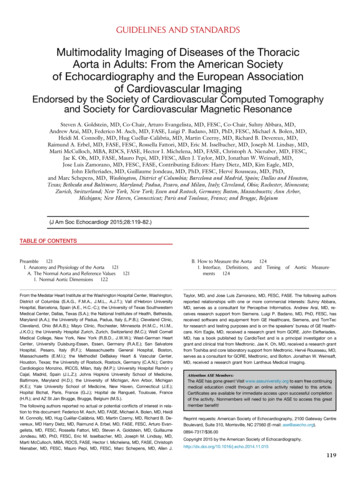
Journal of the American Society of EchocardiographyVolume 28 Number 2Goldstein et al 125Figure 6 Models of the thoracic aorta showing the cut planes of the aortic annulus for each applied imaging modality. (A) Angiography in the 90 left anterior oblique (LAO) projection with an orange arrow indicating the sagittal annulus diameter (left) and in the0 posteroanterior (p.a.) projection with a blue arrow indicating the coronal annulus diameter (right). (B) TTE (left) and 2D TEE (right)left ventricular outflow tract (LVOT) view of the aortic annulus. The cut planes slightly differ because parasternal and midesophagealacoustic are not quite comparable. Both the transthoracic and 2D transesophageal echocardiographic LVOT views resemble asagittal view (bright and dark yellow arrows, respectively). The direction of the arrows in the aortic arch model and the echocardiographic images indicate the scanning direction. Individual adjustments in scan plane direction are shown in the model. (C)Three-dimensional transesophageal echocardiographic cropped images of a sagittal (left) and coronal (right) view with the corresponding diameters (orange and blue arrows). The sagittal and coronal cut planes are depicted in the aortic arch model and theanatomic short-axis view (middle). (D) Dual-source computed tomographic (DSCT) reconstructed images of a sagittal (left) and coronal (right) view with the corresponding diameters (orange and blue arrows). The sagittal and coronal cut planes are depicted in theaor
4. TEE 161 5. IVUS 161 6. MRI 162 C. Imaging Algorithm 162 D. Imaging in Endovascular Repair 162 VI. Aortic Coarctation 162 A. Aortic Imaging in Patients with Unoperated Aortic Coarcta-