Transcription
Technical Investigation Report on Lift Incidentat 478-480 King’s Road, North Point, Hong KongElectrical and Mechanical Services DepartmentJuly 2013
CONTENTSPage3Executive Summary1.Objectives42.Background of the Incident43.Regulatory Control Over Lift Safety44.Technical Information of the Lift Involved in the Incident55.Approach of Investigation66.Observations and Findings77.Conclusions198.Measures to Step up Regulatory Control on Lift Safety20Appendix I:List of Documents Inspected21Appendix II:Basic Structure of Lift222
Executive SummaryOn 2 March 2013, the lift No. 5 at 478-480 King’s Road, North Point,carrying seven passengers, dropped into the bottom of the lift shaft when thelift car ascended from the ground floor and reached the first floor, causinginjuries to all seven passengers inside. It was found that all the foursuspension ropes were broken, and the safety gears were not activated to stopthe lift from falling.The Electrical and Mechanical Services Department (EMSD) hadcompleted the technical investigation with the assistance of independentexperts engaged to find out how the incident occurred. The investigationrevealed that this was a rare incident. All the four suspension ropes werebroken at almost the same time when the lift car ascended from the groundfloor and reached the first floor. The lift car then started to fall but the safetygears were not activated to stop or decelerate the lift even though the fallingspeed had exceeded the activation speed of the overspeed governor.The investigation findings indicated that the suspension ropes broke atbetween 12.5 m to 13.5 m from the fixing points at the lift car. The failure ofthe suspension ropes was due to insufficient lubrication for a prolonged periodof time. This had caused abrasive wear between and within the strands of thesuspension ropes. Moreover, excessive wear between the suspension ropesand the traction sheave was observed. These had resulted in the reduction ofrope diameter and the breakage of individual wires in the strands, hencereducing the strength of the suspension ropes. Prior to the failure, the foursuspension ropes had deteriorated severely to similar extent, with serious wearand rouging, so that the ropes failed at more or less the same time.The investigation revealed that the pawl of the overspeed governor hadfailed to engage onto the teeth of the ratchet wheel during the incident whenthe activation speed of the overspeed governor was reached.Theinvestigation further revealed that improper connection of the deformed tensionspring and rust on the pin of the pawl were attributable to the unsuccessfulengagement of the pawl and ratchet wheel, thus causing the failure to activatethe overspeed governor. Therefore, the safety gears of the lift were notactivated by the overspeed governor to stop the lift from falling.3
Technical Investigation Report on Lift Incidentat 478-480 King’s Road, North Point, Hong Kong on 2 March 20131.Objectives1.1 This report presents the results of the technical investigation conductedby the Electrical and Mechanical Services Department (“EMSD”) on the liftincident occurred at 478-480 King’s Road, North Point, Hong Kong on 2March 2013.2.Background of the Incident2.1 EMSD received an incident report from the call centre of the FireServices Department at around 8:23 pm on 2 March 2013 involving thetrapping of seven passengers inside lift No. 5 at 478-480 King’s Road, NorthPoint, Hong Kong (“the lift”). All seven passengers were rescued by firemenand admitted to hospitals. EMSD staff arrived at the scene at about 9:15 pmon the same day to carry out an investigation into the cause of the incident.2.2 The investigation revealed that all four suspension ropes of the lift werebroken, and the safety gears of the lift were not operated to hold the lift car onthe guide rails. The lift car dropped from 1/F to the bottom of the lift shaft,injuring all seven passengers.3.Regulatory Control over Lift Safety3.1Regulation regimeThe Lifts and Escalators Ordinance (Cap 618) (the “Ordinance”) provides thestatutory framework to ensure lift safety in Hong Kong. Under the Ordinance,only registered lift contractors, registered lift engineers and registered workersare qualified to carry out lift works, including construction, installation andmaintenance services. The responsible person for a lift is required to ensurethat the lift and all its associated equipment or machinery are kept in a properstate of repair and in safe working order. The responsible person shall arrangea registered lift contractor to carry out periodic maintenance at an interval notexceeding a month.The responsible person shall also engage a registeredlift engineer to carry out periodic examination for the lift at an interval notexceeding 12 months.4
3.2Audit inspectionEMSD, as the Registrar and regulatory authority, maintains registers forqualified lift contractors, engineers and workers, and monitors theirperformance to ensure that the services they provided meet the requirementsstipulated in the Ordinance and Codes of Practice for Lift Works and EscalatorWorks (the “Code of Practice”). EMSD adopts a risk-based approach toconduct audit inspections to lift and escalator works to identify anynon-compliance with the requirements of the Ordinance and Codes of Practice.Under the risk-based approach, lifts and escalators are selected for auditinspections taking into account the assessed risks in respect of age, type ofinstallation, nature of works associated with installation, complaint, incident,change-over of maintenance contractor and past performance of the responsibleregistered contractors. On average, more than 9,000 audit inspections areconducted each year.4.Technical Information of the Lift Involved in the Incident4.1 The lift was driven by an alternating current two-speed (AC-2) gearedmachine, with a rated speed of 1.0 metre per second (m/s) and a rated load of900 kg (or 12 persons), serving the G/F, 1/F, 2/F and 3/F of the building. Thetotal travel of the lift was about 12 metres (m).4.2 The lift was suspended by four suspension ropes, each with nominaldiameter of 12 millimetres (mm). The lift adopted a side traction ropingarrangement so that the traction machine of the lift was not placed directlyabove the lift well. Suspension ropes were diverted to the lift car andcounterweight respectively using diverting pulleys.Figure 1 shows thearrangement of the traction machine/sheave and the diverting pulleys of the lift.4.3Technical details of the lift are summarized as follows:MakeTypeDrive ControlDoor ControlRated SpeedRated LoadRope RatioFloors ServedYear of InstallationDate of Last Examinationby Registered Lift Engineer::::::::::MitsubishiElectric passenger liftAlternating current two-speed electric motorHorizontal centre opening1.0 metre per second900 kilograms1 to 1 (machine on top with side traction)G, 1, 2, 3/F197421 November 20125
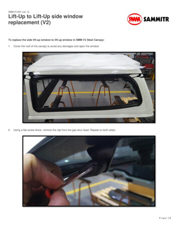
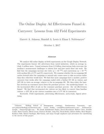
Ropes connected to counterweightRopes connected to lift carDiverting pulleysTraction machineOverspeed GovernorTraction sheaveGovernor RopeGround FloorFigure 1 : Arrangement of the lift5.Approach of Investigation5.1 EMSD conducted the technical investigation with a view to identifyingthe causes leading to the incident. The approach of the investigation isoutlined below:(i)inspect, check and analyse the lift components that were involved in theincident, including the broken suspension ropes, machine brake,overspeed governor, safety gears, guide rails, traction sheave and buffer;(ii)conduct the following tests and examinations with the assistance ofindependent experts :6
thorough examination of the broken suspension ropes andconduct tensile testing of the rope sections to assess the qualityof the ropes; examine the critical components of the lift and conduct on sitesimulation tests to verify the functioning of the lift componentsincluding machine brake simulation test, activation speed testand pull-through test of the overspeed governor; and assess the impact speed of the lift car on the buffer during theincident.(iii) interview and take statements from relevant personnel for collectinginformation related to the incident, including: five maintenance workers and two directors of ShinefordEngineering Limited (“Shineford”);registered lift engineer who carried out statutory annualexamination of the lift on 21 November 2012;workers who replaced the suspension ropes of the lift inSeptember 2010;seven passengers who were involved in the incident;two responsible persons for the lift; andrepresentatives of the occupants on 1/F and 2/F of the building.(iv) review and analyse relevant records including logbook, maintenancerecords provided by Shineford, suspension ropes replacement records,test and examination report issued by the registered lift engineer,occurrence report submitted by Shineford. Records examined are listedin Appendix I.6.Observations and FindingsPossible causes of the incident6.1 According to the indication of the floor selector of the lift, the lift car wasat a position near 1/F before falling of the lift car. According to theinformation provided by one of the lift passengers injured in the lift incident,the lift was ascending from the ground floor and had already reached the firstfloor before the incident.7
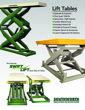
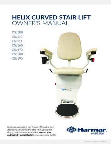
6.2 Based on the on-site observation, it was found that the lift car plungedonto the spring buffer. The following possible causes could lead to suchoutcome:(a) The lift machine brake failed and the lift car fell to the lift pit due tothe weight of the lift car and passengers but the safety system did notfunction. The counterweight overshot upwards and then fell down.The impact force caused breakage of the ropes; or(b) The ropes broke and the safety system failed to function.Lift machine brake6.3 The lift machine brake was designed to hold the lift. A brake test wascarried out on site on 12 March 2013. The results showed that the machinebrake was operating normally and there was no abnormal delay in its operation.The linings of the machine brake were also examined and found to be in areasonably good condition. Thus, the plunging of the lift car was not causedby the failure of the lift machine brake as suggested in section 6.2(a) above.Suspension ropes6.4 The four suspension ropes were found broken at positions between 12.5m and 13.5 m from the fixing points at the lift car, corresponding to the pointwhere the suspension ropes rest on the diverting pulleys when the lift was atG/F (refer to Figure 2). The G/F is the floor with the most frequent stops,thus the above sections of the suspension ropes should experience the largestloading and unloading pressure when the passengers enter and exit the lift car.6.5There are several possible causes of rope breakage including:(a)(b)(c)(d)Overloading;Inadequate strength of the ropes ;Stalling of lift car causing abrasion of ropes on running sheave; andWear and tear leading to a reduction in tensile strength of the ropes.8
Operating conditions6.6 At the time of incident, there were only seven passengers in the lift car.The estimated weight is 455 kg. This was well below the rated load of 900kgof the lift, i.e. twelve passengers. Therefore, overloading as mentioned insection 6.5(a) was not the cause of rope breakage.2aFigure 2 :2bA pictorial view to show the position of breaking points of the suspensionropes (yellow dot) corresponding to different positions of the lift car. Thediagram on the left hand side (2a) shows the lift car on G/F. The diagram onthe right hand side (2b) shows the lift car on 1/F.9
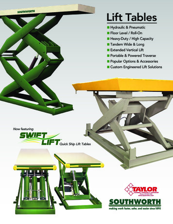
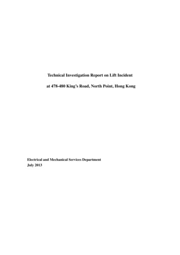
Replacement of suspension ropes6.7 The suspension ropes of the lift concerned were replaced by Shineford inSeptember 2010. Based on the copies of suspension rope certificate anddelivery order submitted by Shineford, the replacement ropes weremanufactured by a rope manufacturer in Japan. Each rope was constructed byeight strands. Each strand contained nineteen wires (Please refer to section 1of Appendix II). The nominal diameter of the ropes is 12 mm. Thespecifications of the ropes complied with that specified by the lift manufacturer.Besides, an identification ribbon for the ropes produced by this manufacturerwas found in the fibre cores of the broken suspension ropes. The abovefindings together with the findings in section 6.15 indicate that the scenariosuggested in section 6.5(b) was not the cause of the rope breakage.Examination of suspension ropes6.8 The suspension ropes were carefully examined by a lift expert. No signof burnt mark was found indicating that rubbing between stationary ropesagainst a rotating traction sheave had not occurred. Therefore, the scenario assuggested in section 6.5(c) was not the cause of rope breakage.6.9 The four suspension ropes were found broken at about the same position(i.e. near to the diverting pulleys). Visible wear and red iron oxide particles(also known as rouge) could be observed from the suspension ropes, inparticular at sections close to the breakage points. Figure 3 shows thesectional view of a typical suspension rope of a lift.6.10 At the very ends of failed strands in all ropes, only king wires and innerwires were found. The fibre cores and the outer wires were completelymissing (refer to Figure 3a). Adjacent to the failed ends, the strands of theropes opened up after failure. Detailed examination revealed that the fibrecores of the ropes could not be found in the suspension ropes until at somedistance from the failed ends. It was suspected that movement of the wireshad already cut the fibre cores into small pieces, which had escaped from theropes when they broke (refer to Figure 3b). Besides, notches formed on theouter wires of the strands were observed and these indicated that abrasion hadoccurred between strands of the ropes (refer to Figure 3c).10
ValleyKing wireInner wireOuter wireFibre coreStrandWireCrown (surface of thesuspension rope)Figure 3 : Sectional view of a wire ropeFigure 3a : A closer view of the brokenFigure 3b : The fibre cores wereend of a suspension rope.missing in a short section next to theOnly innerwires and king wires remained.failed end of the rope.Figure 3c : Notches formed due toabrasion between strands.11
6.11 Away from the failed ends, the suspension ropes were relatively dry androuge was observed in the valleys between strands along a substantial sectionof the suspension ropes. Moreover, wear was clearly visible along outer wiresfor most of the length of all ropes (refer to Figure 4).Figure 4 : Wear of the rope along outersurface (crown wear) and red ironoxide particles (rouge) in the valleysbetween strands.Traction sheave6.12 The grooves of the traction sheave were examined. According to thedesign, an undercut is made to each groove so that the pressure between thesuspension rope and the groove would be increased (see Figure 5). Thisfeature helps to increase the friction between the ropes and the sheave toprovide the traction required for effective operation of the lift.6.13 The examination revealed that the four grooves in contact with the ropeswere found to have worn down to the bottom of the undercut (see Figure 6).A traction sheave with this substantial groove wear would result in rope slipand hence extra abrasion of the rope as shown in Figure 4.RopeGroove undercutFigure 6 : Groove worn down to thebottom of the undercutFigure 5 : Undercut of sheave groove12
Tensile strength of the suspension ropes6.14 The suspension ropes were subject to wear and tear thus leading to areduction in tensile strength. Tensile tests on the ropes were carried out toassess the extent of reduction in strength. Eight of the test pieces were cutfrom the four broken suspension ropes. Three of them were cut from theposition near the fixing points to the lift while the other five were cut from theropes near to the failed ends.6.15 The test samples cut from the ropes near to the fixed ends did not passover the traction sheave, and hence were not subject to wear and tear. Theaverage breaking load of the three test samples was found to be 69.8 kN (ascompared to the breaking load of 58.8 kN specified on the certificate for thesuspension ropes). The test results indicated that the strength of thesuspension ropes at these sections complied with the requirement as indicatedon the certificate. See also section 6.7.6.16 With regard to the samples collected from the ropes near to the failedends, the tests indicated the average strength of the five samples was 38.5 kNwith a minimum of 23.7 kN for one of the samples. The test results indicatedthat the tensile strengths of these sections which were subject to substantialwear and tear during service had been significantly reduced to about 34% of itsdesign strength. Further reduction in the tensile strength of the ropes at thefailed ends was expected as they were the weakest points of the ropes.Possible cause of rope breakage6.17 From the results of the tensile tests and examination of the suspensionropes, it is obvious that the failure of the ropes was due to excessive wear andtear of the ropes. Due to insufficient lubrication for a prolonged period oftime since their replacement in September 2010, the fibre core of the ropesection had dried up and could not provide the strands with the necessarylubrication and radial support. The strands came in contact with each othercausing abrasive wear between and within strands. These had resulted insignificant reduction in the strength of the suspension ropes. Immediatelybefore the failure, the four suspension ropes had deteriorated severely to asimilar extent. The remaining strength of the ropes could no longer supportthe weight of the lift car with passengers inside combined with the dynamicloads when the lift stopped on 1/F. The ropes failed at almost the same time.13
Overspeed governor and safety gears6.18 The overspeed governor and safety gears of the lift are designed to comeinto operation when the speed of the lift exceeds the specified limit. Thesafety gears on the lift car would be activated to hold the lift car onto the guiderails, thus leaving clamping marks on the guide rail surfaces. Closeexamination of the guide rails revealed that the guide rails were clear of anyclamping marks. The findings showed that the safety gears were not activatedduring the incident.6.19 The followings are possible causes of the non-operation of the safetygears:(a)(b)The falling speed had not reached the designed level to activate theoverspeed governor and safety gears; orThe overspeed governor and/or safety gears did not operate evenwhen the activation speed was reached.Falling speed of the lift car6.20 The breakage of the suspension ropes and non-operation of the safetygears led to the plunging of the lift car into the lift pit. Figure 7 shows thedeformation of the bottom part of the lift car supporting frame (“bottomframe”). The deformation of the bottom frame was caused by the impact ofthe lift car to the spring buffer in the lift pit.Figure 7 : Outlook of the deformed lift car bottom frame.14
Impact speed estimation6.21 The impact speed of the falling lift car was analysed. The impact speedof the lift car loaded with seven passengers should be above 2.7 m/s. Thisspeed was well above the activation speed (1.4 m/s) of the overspeed governorof the lift. The analysis shows that overspeed governor should have beenactivated before the lift car reached the buffer.Testing of the overspeed governor6.22 During the on-site inspection immediately after the incident on 2 March2013, the electrical switch of the overspeed governor was found activated.Besides, the pawl of the overspeed governor was released and had come closeto the valley between two teeth of the ratchet wheel. However, it was notfully engaged with the ratchet wheel. These indicated that the overspeedgovernor had already reached its activation speed.for operation of pawl, see figure 11ElectricalswitchpawlpawlGovernor sheaveRatchet wheelFigure 8 : Overspeed governor of the lift. The Figure on the left shows that the pawlof the overspeed governor had been released and came close to the valley between twoteeth of the ratchet wheel.6.23 Another test was conducted to verify if the activation speed of theoverspeed governor was correctly set. The test was conducted by driving theoverspeed governor sheave with a variable speed tool when the governor ropewas detached from the governor sheave. (see also Figure 9) Test resultsshowed that the activation speeds (1.3 m/s for activating the electrical switchand 1.4 m/s for activating the safety gears) were in line with the speeds shownon the data plate of the overspeed governor and were in compliance with therequirements specified in the Code of Practice on the Design and Constructionof Lifts and Escalators issued by the Electrical and Mechanical ServicesDepartment.15
Figure 9 : Governor activation speed testarrangement – governor sheave being drivenby a variable speed tool6.24 Although the activation speed of the overspeed governor was correctlyset, it was noticed that a gap was found between the governor rope and the shoeof the governor, signifying that the governor rope was not gripped by the shoein the incident. (refer to Figure 10)ShoeGapFigure 10 : Gap between the shoe ofthe governor and the governor rope,indicating no gripping of thegovernor rope by the shoe in theincident.Governor rope6.25 It was mentioned in section 6.22 that, after the incident, the pawl of theoverspeed governor was released and had come close to the valley between twoteeth of the ratchet wheel but was not in the fully engaged position. Due tothe failure of engagement of the pawl with the ratchet wheel, the subsequentmechanism to activate the safety gears could not be operated to prevent the liftcar from falling down.16
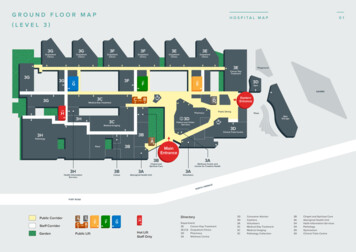
The pawl6.26 The pawl of the overspeed governor was spring-loaded to ensure itsengagement with the ratchet wheel when the latch was released.Theoperation of the pawl and ratchet wheel is shown in Figure 11. It was foundthat the tension spring of the pawl was not properly connected to the pawl andthe connection end of the spring was deformed (see Figure 12).Ratchet wheelPawl (refer to Figure 8)Pin (refer to Figure 13)LatchSpring (refer to Figure 12)Spring connectionhole on pawlPawl engaged withratchet wheelProper springconnectionImproper springconnectionLatch releasedFigure 11 : Diagrams showing the operation of the pawl and ratchet wheel of theoverspeed governor. The lower diagram shows the latch released and the pawlengaged with the ratchet wheel.17
Point ofdeformationSpringFigure 12:Photo shows deformation of the spring end.6.27 The pin (pivot joint) of the pawl was dismantled and examined. Rustwas found on the surface of the pin. (see Figure 13). The rust would increasethe friction of the pin and impair the swift response of the pawl of theoverspeed governor.pawlFigure 13 : Pin of the pawl of theoverspeed governor.rust18
Possible cause of failure of the safety system6.28 Based on the observations mentioned in 6.22, the pawl of the overspeedgovernor failed to fully engage with the ratchet wheel during the incidentdespite that the activation speed of the overspeed governor had been reachedand the latch of the pawl was released. The improper connection of thetension spring and the rust on the pin of the pawl were attributable to theunsuccessful engagement. Therefore, the ratchet wheel failed to bring theshoe of the governor gripping onto the governor rope and hence did notactivate the safety gears.7.ConclusionsBased on the findings of the investigation, the following conclusions aredrawn:7.1 All the four suspension ropes broke at almost the same time when the liftcar, carrying seven passengers, was ascending from G/F and reached 1/F. Thelift car then started to fall but the safety gears were not activated to stop ordecelerate the lift car despite the falling speed of it had exceeded the activationspeed of the overspeed governor.7.2 The suspension rope breakage was primarily due to wear and tear causedby insufficient lubrication to the suspension ropes for a prolonged period oftime, and this had led to excessive wear and rouging being formed on thesuspension ropes prior to the incident. The strength of the ropes had beensubstantially reduced which caused all the suspension ropes to break in theincident.7.3 The overspeed governor failed to activate the operation of the safetygears to stop the lift car. Despite that the activation speed was reached, thepawl of the overspeed governor failed to engage with the ratchet wheel duringthe incident, rendering it unable to activate the safety gears of the lift. Theimproper connection of the tension spring of the pawl and the rusty pin of thepawl were attributable to such unsuccessful engagement.19
8.Measures to Step up Regulatory Control on Lift Safety8.1 Subsequent to the lift incident, EMSD had taken immediate action toinspect all the lifts maintained by Shineford within three days immediatelyafter the incidents, ensuring the safe working order of these lifts.8.2 On satisfying that Shineford had failed to carry out the lift worksproperly and safely, the Director of Electrical and Mechanical Services, in thecapacity of the Registrar under the Lifts and Escalators Ordinance, exercisedthe power under the Ordinance to suspend Shineford’s registration as aregistered lift contractor for six months commencing 1 May 2013.8.3 EMSD had reminded all registered lift contractors to strictly observe theCode of Practice’s requirements in conducting lift maintenance. EMSD hadalso stepped up inspection of lifts maintained by registered lift contractors withrelatively low performance rating in the Contractors’ Performance Rating (CPR)Scheme.8.4 Taking into account the findings of this investigation, EMSD had steppedup the monitoring of registered lift contractors, including the following :i. More inspections would be accorded to the lifts maintained byregistered contractors with relatively low performance rating in the CPRScheme. EMSD would also increase the frequency of audit visits toregistered contractors with low CPR ranking.ii. As suspension ropes are the essential component of a lift, theregistered contractors/engineers would be required to submit detailedinspection reports of the ropes after the annual examinations of lifts.iii. Separately, the CPR Scheme would be critically reviewed with aview to rationalizing the Scheme to reflect the performance of registeredcontractors.8.5 To facilitate responsible persons to better understand their duties andresponsibilities under the Ordinance, EMSD would step up publicity and publiceducation by arranging more seminars for responsible persons to enhance theirknowledge on daily management of lift and entering maintenance contractswith registered lift contractors.20
Appendix IList of Documents Inspected during the Investigation1.Delivery order and quotation for replacement of hoisting ropes of the liftNo. 5 (lift involved in the incident) dated 8 September 2010 issued byShineford to lift owner2.“Periodic maintenance report” of Shineford for lift No. 5, 6, 7 at 480King’s Road between March 2012 and February 20133.Circuit diagram of lift no. 5 kept in the machine room4.Logbook for lift No. 5, 6, 75.Safety certificate issued by the registered lift engineer for the periodicexamination of lift no. 5 carried out on 21 November 20126.“Lift Examination Record” of Shineford for the periodic examination oflift no. 5 carried out on 21 November 20127.“Items for Periodic Maintenance of Lifts” of Shineford (standard chart)8.“Notification of Lift Incident” – Form LE27 dated 4 March 2013submitted by Shineford on behalf of the responsible persons for the lift9.Investigation report submitted by Shineford10. Training records of the staff/workers of Shineford11. “Safety Handbook” dated 11 October 2007 issued by Shineford12. “Works Instruction – Issue related to Periodic Safety Test of Lifts”,document no. V2-13 issued by Shineford13. Technical information, manufacturer’s maintenance manual/scheduleprovided by the agent of the manufacturer of lift No. 514. Manufacturer’s Certificate of the suspension ropes for lift No. 521
Appendix IIBasic Structure of LiftThe basic structure of a lift consists of a vertical lift well in which the lift car isplaced. Guide rails are installed inside the lift well, which restrict the lift carto move up and down in a controlled manner.Multiple steel ropes (suspension ropes) are used to move the lift car, which aredriven by the traction machine installed inside the machine room, usuallylocated on the roof level. One end of these suspension ropes is connected tothe lift car and the other end is connected to the counterweight for balancing.The weight of counterweight is generally determined by the weight of lift carplus 45% - 50% of the rated loading capacity. When the lift car moves, thecounterweight will move in the opposite direction. The traction machine isfitted with a traction sheave, over which suspension ropes are laid. Thesuspension ropes are in contact with the grooves of the sheave and driven bymeans of friction between the contact surfaces. The suspension ropes andtraction sheave are subject to wear and tear during lift operation, and have to bechecked and replaced regularly.The suspension ropes shall have a tensile grade corresponding to thosespecified in ISO 4344 or other relevant international standard. The safetyfactor (ratio between minimum breaking load and the maximum force in therope) of the suspension rope shall be at least 12.In spite of the high safety factors, suspension ropes should be replacedimmediately when the rope has worn down by more than 10% of its diameteror the number of wire breaks is excessive in order to keep the lift in safeworking order.The traction machine is used to drive the traction sheave so as to raise or lowerth
2.1 EMSD received an incident report from the call centre of the Fire Services Department at around 8:23 pm on 2 March 2013 involving the trapping of seven passengers inside lift No. 5 at 478-480 King's Road, North Point, Hong Kong ("the lift"). All seven passengers were rescued by firemen and admitted to hospitals.