Transcription
Dell EMC PowerEdge R340Technical Specifications GuideRegulatory Model: E58S SeriesRegulatory Type: E58S001
Notes, cautions, and warningsNOTE: A NOTE indicates important information that helps you make better use of your product.CAUTION: A CAUTION indicates either potential damage to hardware or loss of data and tells you how to avoid the problem.WARNING: A WARNING indicates a potential for property damage, personal injury, or death. 2018 Dell Inc. or its subsidiaries. All rights reserved. Dell, EMC, and other trademarks are trademarks of Dell Inc. or its subsidiaries. Other trademarksmay be trademarks of their respective owners.2018 - 12Rev. A00
Contents1 Dell EMC PowerEdge R340 system overview. 4Front view of the system. 4Control panels.5Rear view of the system. 62 Technical specifications. 7Chassis dimensions. 8System weight.9Processor specifications.9PSU specifications. 9Cooling fans specifications.9System battery specifications.10Expansion card riser specifications.10Memory specifications. 10Storage controller specifications. 10Drive specifications. 11Drives. 11Optical drives. 11Ports and connectors specifications. 11USB ports specifications. 11NIC ports specifications.12Serial connector specifications. 12VGA ports specifications. 12Video specifications.12Environmental specifications.12Standard operating temperature.14Expanded operating temperature. 14Particulate and gaseous contamination specifications. 153 System diagnostics and indicator codes . 16System health and system ID indicator codes. 16iDRAC Direct LED indicator codes.17NIC indicator codes. 17Power supply unit indicator codes.18Drive indicator codes.194 Getting help.20Recycling or End-of-Life service information. 20Contacting Dell.20Accessing system information by using QRL. 20Quick Resource Locator for Dell EMC PowerEdge R340 system. 21Receiving automated support with SupportAssist . 21Contents3
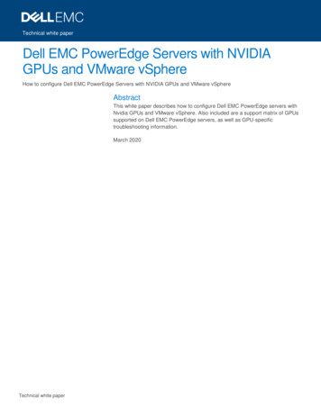
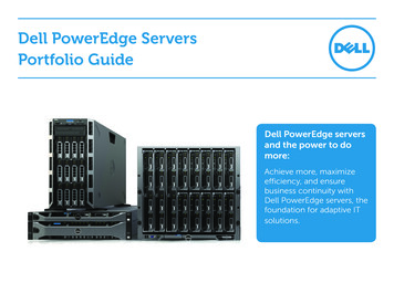
1Dell EMC PowerEdge R340 system overviewThe Dell EMC PowerEdge R340 system is a 1U server that supports: One Intel Xeon Scalable processor Four DIMM slots Two AC power supply units Up to eight 2.5-inch or four 3.5-inch SAS, SATA drivesFor more information about supported drives, see the Drive specifications section.NOTE: All instances of SAS, SATA drives, and SSDs are referred to as drives in this document, unless specified otherwise.Topics: Front view of the system Rear view of the systemFront view of the systemNOTE: The 8 x 2.5-inch configuration is shorter than the 4 x 3.5-inch configuration.Figure 1. Front view of the 8 x 2.5-inch drive system1Left control panel2Optical drive (optional)3Right control panel4Information tag5Drives (8)4Dell EMC PowerEdge R340 system overview
Figure 2. Front view of the 4 x 3.5-inch drive system1Left control panel2Optical drive (optional)3Right control panel4Information tag5Drives (4)For more information about the ports, see the Technical Specifications section.Control panelsLeft control panelFigure 3. Left control panel view1System health and system ID indicatorDell EMC PowerEdge R340 system overview5
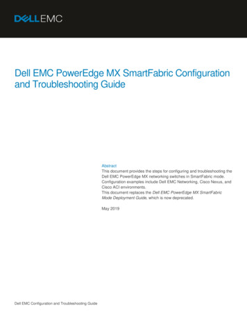
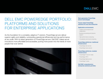
Right control panelFigure 4. Right control panel view1Power button3iDRAC direct Micro USB port2USB 2.0-compliant portNOTE: For more information on the ports, see the Ports and connectors specifications section.Rear view of the systemFigure 5. Rear view of the system1Serial port2NIC port (GB 1)3NIC port (GB 2)4Half-height PCIe expansion card slot5Full-height PCIe expansion card slot6Power supply unit 17Power supply unit 28System identification button9System status indicator cable port (CMA)10USB 3.0 port (2)11iDRAC9 dedicated network port12VGA portNOTE: For more information about the ports and connectors, see the Ports and connectors specifications section.6Dell EMC PowerEdge R340 system overview
2Technical specificationsThe technical and environmental specifications of your system are outlined in this section.Topics: Chassis dimensions System weight Processor specifications PSU specifications Cooling fans specifications System battery specifications Expansion card riser specifications Memory specifications Storage controller specifications Drive specifications Ports and connectors specifications Video specifications Environmental specificationsTechnical specifications7
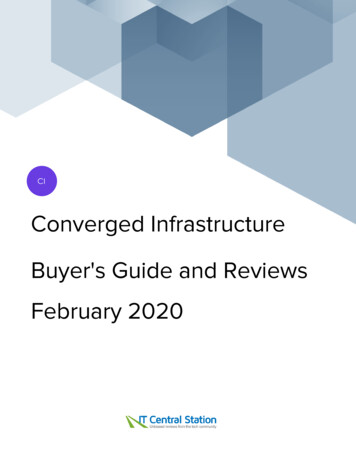
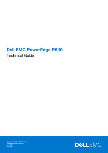
Chassis dimensionsFigure 6. Chassis dimensionsTable 1. Dell EMC PowerEdge R340 chassis dimensionsXaXbYZaZb482.0 mm(18.98 inches)434.0 mm(17.08 inches)42.8 mm(1.68 inches)With bezel:35.64 mm(1.4 inches)Withoutbezel:22.0 mm(0.87 inches)8 x 2.5 inchconfiguration483.72 mm(19.04 inches)8 x 2.5 inchconfiguration4 x 3.5 inchconfiguration534.5 mm(21.04 inches)4 x 3.5 inchconfiguration8Technical specificationsZc522.85 mm(20.58 inches)573.6 mm (22.58inches)
System weightTable 2. Dell EMC PowerEdge R340 system weightSystem configurationMaximum weight (with all drives/SSDs)8 x 2.5-inch configuration12 kg (26.5 lb)4 x 3.5-inch configuration13.2 kg (29.10 lb)Processor specificationsTable 3. Dell EMC PowerEdge R340 processor specificationsSupported processorNumber of processors supportedIntel Xeon Scalable ProcessorOnePSU specificationsThe Dell EMC PowerEdge R340 system supports up to two AC power supply units (PSUs).Table 4. Dell EMC PowerEdge R340 PSU specificationsPSU350 W nt- 1531 BTU/hrRedundant 1356 BTU/hr550 W ACPlatinum2107 BTU/hrFrequencyVoltageACHigh line 100–240 V50/60 Hz50/60 HzCurrentLow line 100–120 V100–240 V AC, 350 WautorangingNA4.8 A–2.4 A100–240 V AC, 550 WautorangingNA7.4 A–3.7 ANOTE: This system is also designed to connect to the IT power systems with a phase-to-phase voltage not exceeding 230 V.Cooling fans specificationsThe Dell EMC PowerEdge R340 system supports the following cooling fans.NOTE: When selecting or upgrading the system configuration, to ensure optimum power utilization, verify the system powerconsumption with the Dell Energy Smart Solution Advisor available at Dell.com/ESSA.Table 5. Dell EMC PowerEdge R340 fan support matrixFront storagePSU typeFan 1Fan 2Fan 3Fan 48 x 2.5-inchRedundant 350WRequired, if the PERCcard and/or expansionriser is installedRequiredRequiredRequired4 x 3.5-inchTechnical specifications9
Front storagePSU typeFan 1Fan 2Fan 3Fan 48 x 2.5-inchRedundant 550WRequired, if the PERCcard and/or expansionriser is installedRequiredRequiredRequired4 x 3.5-inchOptional - .System battery specificationsThe Dell EMC PowerEdge R340 system supports CR 2032 3.0-V lithium coin cell system battery.Expansion card riser specificationsThe Dell EMC PowerEdge R340 system supports up to two PCI express (PCIe) generation 3.Table 6. Expansion card slots supported on the system boardPCIe slotRiserPCIe slot heightPCIe slot lengthLink widthSlot widthSlot 1x8 PCIeLow-profileHalf-lengthx4x8Slot 2x16 fileHalf-lengthx8x8Internal PERC x8 PCIeMemory specificationsThe PowerEdge R340 system supports the following memory specifications for optimized operation.Table 7. Memory specificationsDIMM typeDIMM rankSingle rankUDIMMDual rankDIMM capacityMinimum RAM8 GB8 GB32 GB16 GB16 GB64 GB8 GB8 GB32 GB16 GB16 GB64 GBTable 8. Memory module socketsMemory module socketsFour 288-pinSpeed2666 MT/sStorage controller specificationsThe Dell EMC PowerEdge R340 system supports the following controller cards:Table 9. Dell EMC PowerEdge R340 system controller cardsInternal controllersExternal controllers PERC H730P10Technical specificationsMaximum RAM12Gbps SAS Ext. HBA
Internal controllers External controllersPERC H330S140HBA330Drive specificationsDrivesNOTE: The 8 x 2.5-inch configuration is shorter than the 4 x 3.5-inch configuration.The Dell EMC PowerEdge R340 system supports: 8 x 2.5-inch hot-swappable SAS, SATA, or SSD 4 x 3.5-inch hot-swappable SAS, SATA, or SSD 4 x 2.5-inch hot-swappable SAS, SATA, or SSD in 3.5-inch adaptersBackplane: Up to 8 x 2.5-inch SAS, SATA, or SSD drives Up to 4 x 3.5-inch SAS, SATA, or SSD drivesOptical drivesThe Dell EMC PowerEdge R340 system supports the following optical drives.Table 10. Supported optical drive typeSupported drive typeSupported number of drivesDedicated SATA DVD-ROM drive or DVD /-RW driveOnePorts and connectors specificationsUSB ports specificationsTable 11. Dell EMC PowerEdge R340 system USB specificationsFrontUSB port typeRearNo. of portsUSB 2.0-compliantportOneMicro USB 2.0compliant port foriDRAC DirectOneUSB port typeUSB 3.0-compliantportsInternalNo. of portsTwoUSB port typeInternal USB 3.0compliant portNo. of portsOneNOTE: The micro USB 2.0 compliant port can only be used as an iDRAC Direct or a management port.Technical specifications11
NIC ports specificationsThe Dell EMC PowerEdge R340 system supports up to two 10/100/1000 Mbps Network Interface Controller (NIC) ports that are locatedon the back panel.Serial connector specificationsThe Dell EMC PowerEdge R340 system supports one serial connector on the back panel, which is a 9-pin connector, Data TerminalEquipment (DTE), 16550-compliant.VGA ports specificationsThe PowerEdge R340 system supports one DB-15 VGA port located on the back panel of the system.Video specificationsThe Dell EMC PowerEdge R340 system supports integrated Matrox G200 graphics controller with 16 MB of video frame buffer.Table 12. Supported video resolution optionsResolutionRefresh rate (Hz)Color depth (bits)640 x 48060, 728, 16, 24800 x 60060, 75, 858, 16, 241024 x 76860, 75, 858, 16, 241152 x 86460, 75, 858, 16, 241280 x 102460, 758, 16, 24Environmental specificationsNOTE: For additional information about environmental certifications, refer to the Product Environmental Datasheet located withthe Manuals & Documents on Dell.com/support/home.Table 13. Temperature ��65 C (-40–149 F)Continuous operation (for altitude less than 950 m or 10–35 C (50–95 F) with no direct sunlight on the equipment3117 ft)Fresh airFor information about fresh air, see the Expanded operating temperature section.Maximum temperature gradient (operating andstorage)20 C/h (36 F/h)12Technical specifications
Table 14. Relative humidity specificationsRelative humiditySpecificationsStorage5% to 95% RH with 33 C (91 F) maximum dew point.Atmosphere must be noncondensing at all times.Operating10% to 80% RH with 29 C (84.2 F) maximum dew point.Table 15. Maximum vibration specificationsMaximum vibrationSpecificationsOperating0.26 Grms at 5 Hz to 350 Hz (all operation orientations)Storage1.88 Grms at 10 Hz to 500 Hz for 15 minutes (all six sides tested)Table 16. Maximum shock pulse specificationsMaximum shock pulseSpecificationsOperatingSix consecutively executed shock pulses in the positive and negative x, y, and zaxis of 6 G for up to 11 ms.StorageSix consecutively executed shock pulses in the positive and negative x, y, and zaxis (one pulse on each side of the system) of 71 G for up to 2 ms.Table 17. Maximum altitude specificationsMaximum altitudeSpecificationsOperating3048 m (10,000 ft)Storage12,000 m (39,370 ft)Table 18. Operating temperature derating specificationsOperating temperature deratingSpecificationsUp to 35 C (95 F)Maximum temperature is reduced by 1 C/300 m (1 F/547 ft), above 950 m (3,117ft).35–40 C (95–104 F)Maximum temperature is reduced by 1 C/175 m (1 F/319 ft), above 950 m (3,117ft).40–45 C (104–113 F)Maximum temperature is reduced by 1 C/125 m (1 F/228 ft), above 950 m (3,117ft).Technical specifications13
Standard operating temperatureTable 19. Standard operating temperature specificationsStandard operating temperatureSpecificationsContinuous operation (for altitude less than 950 m or 3117ft)10–35 C (50–95 F) with no direct sunlight on the equipment.Expanded operating temperatureTable 20. Expanded operating temperature specificationsExpanded operating temperatureSpecificationsContinuous operation5 C–40 C at 5% to 85% RH with 29 C dew point.NOTE: Outside the standard operating temperature(10 C–35 C), the system can operate continuously intemperatures as low as 5 C and as high as 40 C.For temperatures 35 C– 40 C, derate maximum allowabletemperature by 1 C per 175 m (1 F per 319 ft) above 950 m (3,1171ft). 1% of annual operating hours-5 C–45 C at 5% to 90% RH with 29 C dew point.NOTE: Outside the standard operating temperature(10 C–35 C), the system can operate down to -5 C orup to 45 C for a maximum of 1% of its annual operatinghours.For temperatures 40 C– 45 C, derate maximum allowabletemperature by 1 C per 125 m (1 F per 228 ft) above 950 m (3.117ft).NOTE: When operating in the expanded temperature range, the performance of the system may be impacted.NOTE: When operating in the expanded temperature range, ambient temperature warnings may be reported on the SystemEvent Log.Expanded operating temperature restrictions Do not perform a cold startup below 5 C. The operating temperature specified is for a maximum altitude of 950m for Fresh Air Cooling. Redundant power supply units are required. Four redundant system fans are required. GPU is not supported. Support for up to 80W processor. Non-Dell qualified peripheral cards and/or peripheral cards greater than 25 W are not supported. Tape backup unit is not supported.14Technical specifications
Particulate and gaseous contamination specificationsThe following table defines the limitations that help avoid any damages to the IT equipment and/or, or both failure from particulate andgaseous contamination. If the levels of particulate or gaseous pollution exceed the specified limitations and results in equipment damage orfailure, you must rectify the environmental conditions. Remediation of environmental conditions is the responsibility of the customer.Table 21. Particulate contamination specificationsParticulate contaminationSpecificationsAir filtrationData center air filtration as defined by ISO Class 8 per ISO 14644-1with a 95% upper confidence limit.NOTE: This condition applies to data center environmentsonly. Air filtration requirements do not apply to ITequipment designed to be used outside a data center, inenvironments such as an office or factory floor.NOTE: Air entering the data center must have MERV11 orMERV13 filtration.Conductive dustAir must be free of conductive dust, zinc whiskers, or otherconductive particles.NOTE: This condition applies to data center and non-datacenter environments.Corrosive dust Air must be free of corrosive dust.Residual dust present in the air must have a deliquescent pointless than 60% relative humidity.NOTE: This condition applies to data center and non-datacenter environments.Table 22. Gaseous contamination specificationsGaseous contaminationSpecificationsCopper Coupon Corrosion 300 Å/month per Class G1 as defined by ANSI/ISA71.04-1985.Silver Coupon Corrosion 200 Å/month as defined by AHSRAE TC9.9.NOTE: Maximum corrosive contaminant levels measured at 50% relative humidity.Technical specifications15
3System diagnostics and indicator codesThe diagnostic indicators on the system front panel display system status during system startup.Topics: System health and system ID indicator codes iDRAC Direct LED indicator codes NIC indicator codes Power supply unit indicator codes Drive indicator codesSystem health and system ID indicator codesThe system health and system ID indicator is located on the left control panel of your system.Figure 7. System health and system ID indicator16System diagnostics and indicator codes
Table 23. System health and system ID indicator codesSystem health and system ID indicatorcodeConditionSolid blueIndicates that the system is turned on, system is healthy, and system ID mode is not active.Press the system health and system ID button to switch to system ID mode.Blinking blueIndicates that the system ID mode is active. Press the system health and system ID button toswitch to system health mode.Solid amberIndicates that the system is in fail-safe mode. If the problem persists, see the Getting helpsection.Blinking amberIndicates that the system is experiencing a fault. Check the System Event Log for specificerror messages. For information about the event and error messages generated by the systemfirmware and agents that monitor system components, see the Error Code Lookup page, atqrl.dell.comiDRAC Direct LED indicator codesThe iDRAC Direct LED indicator lights up to indicate that the port is connected and is being used as a part of the iDRAC subsystem.You can configure iDRAC Direct by using a USB to micro USB (type AB) cable, which you can connect to your laptop or tablet. Thefollowing table describes iDRAC Direct activity when the iDRAC Direct port is active:Table 24. iDRAC Direct LED indicator codesiDRAC Direct LEDindicator codeConditionSolid green for two seconds Indicates that the laptop or tablet is connected.Flashing green (on for twoseconds and off for twoseconds)Indicates that the laptop or tablet connected is recognized.Powers offIndicates that the laptop or tablet is unplugged.NIC indicator codesEach NIC on the back of the system has indicators that provide information about the activity and link status. The activity LED indicatorindicates if data is flowing through the NIC, and the link LED indicator indicates the speed of the connected network.Figure 8. NIC indicator codes1Link LED indicator2Activity LED indicatorSystem diagnostics and indicator codes17
Table 25. NIC indicator codesStatusConditionLink and activity indicators are off.The NIC is not connected to the network.Link indicator is green, and activity indicator is blinkinggreen.The NIC is connected to a valid network at its maximum port speed, anddata is being sent or received.Link indicator is amber, and activity indicator is blinkinggreen.The NIC is connected to a valid network at less than its maximum portspeed, and data is being sent or received.Link indicator is green, and activity indicator is off.The NIC is connected to a valid network at its maximum port speed, anddata is not being sent or received.Link indicator is amber, and activity indicator is off.The NIC is connected to a valid network at less than its maximum portspeed, and data is not being sent or received.Link indicator is blinking green, and activity is off.NIC identify is enabled through the NIC configuration utility.Power supply unit indicator codesAC power supply units (PSUs) have an illuminated translucent handle that serves as an indicator. The indicator shows whether power ispresent or if a power fault has occurred.Figure 9. AC PSU status indicator1AC PSU status indicator/handleTable 26. AC PSU status indicator codesPower indicator codesConditionGreenA valid power source is connected to the PSU and the PSU is operational.Blinking amberIndicates a problem with the PSU.Not illuminatedPower is not connected to the PSU.Blinking greenWhen the firmware of the PSU is being updated, the PSU handle blinks green.CAUTION: Do not disconnect the power cord or unplug the PSU when updating firmware. Iffirmware update is interrupted, the PSUs do not function.Blinking green and turns offWhen hot-plugging a PSU, the PSU handle blinks green five times at a rate of 4 Hz and turns off. Thisindicates a PSU mismatch with respect to efficiency, feature set, health status, or supported voltage.CAUTION: If two PSUs are installed, both the PSUs must have the same type of label; forexample, Extended Power Performance (EPP) label. Mixing PSUs from previous generations ofPowerEdge servers is not supported, even if the PSUs have the same power rating. This resultsin a PSU mismatch condition or failure to power on the system.18System diagnostics and indicator codes
Power indicator codesConditionCAUTION: When correcting a PSU mismatch, replace only the PSU with the blinking indicator.Swapping the PSU to make a matched pair can result in an error condition and unexpectedsystem shutdown. To change from a high output configuration to a low output configuration orvice versa, you must power off the system.CAUTION: AC PSUs support both 240 V and 120 V input voltages with the exception of TitaniumPSUs, which support only 240 V. When two identical PSUs receive different input voltages, theycan output different wattages, and trigger a mismatch.CAUTION: If two PSUs are used, they must be of the same type and have the same maximumoutput power.Drive indicator codesThe LEDs on the drive carrier indicates the state of each drive. Each drive carrier in your system has two LEDs: an activity LED (green) anda status LED (bicolor, green/amber). The activity LED flashes whenever the drive is accessed.Figure 10. Drive indicators1Drive activity LED indicator3Drive capacity label2Drive status LED indicatorNOTE: If the drive is in the Advanced Host Controller Interface (AHCI) mode, the status LED indicator does not turn on.Table 27. Drive indicator codesDrive status indicator codeConditionFlashes green twice per secondIdentifying drive or preparing for removal.OffDrive ready for removal.NOTE: The drive status indicator remains off until all drives areinitialized after the system is turned on. Drives are not readyfor removal during this time.Flashes green, amber, and then turns offPredicted drive failure.Flashes amber four times per secondDrive failed.Flashes green slowlyDrive rebuilding.Solid greenDrive online.Flashes green for three seconds, amber for three seconds, and Rebuild stopped.then turns off after six secondsSystem diagnostics and indicator codes19
4Getting helpTopics: Recycling or End-of-Life service information Contacting Dell Accessing system information by using QRL Receiving automated support with SupportAssistRecycling or End-of-Life service informationTake back and recycling services are offered for this product in certain countries. If you want to dispose of system components, visitDell.com/recyclingworldwide and select the relevant country.Contacting DellDell provides several online and telephone based support and service options. If you do not have an active internet connection, you can findcontact information about your purchase invoice, packing slip, bill, or Dell product catalog. Availability varies by country and product, andsome services may not be available in your area. To contact Dell for sales, technical assistance, or customer service issues:1Go to Dell.com/support/home2Select your country from the drop-down menu on the lower right corner of the page.3For customized support:abEnter your system Service Tag in the Enter your Service Tag field.Click Submit.The support page that lists the various support categories is displayed.4For general support:abcSelect your product category.Select your product segment.Select your product.The support page that lists the various support categories is displayed.5For contact details of Dell Global Technical Support:abClick Global Technical SupportThe Contact Technical Support page is displayed with details to call, chat, or e-mail the Dell Global Technical Support team.Accessing system information by using QRLPrerequisitesEnsure that your smartphone or tablet has the QR code scanner installed.The QRL includes the following information about your system: How-to videos Reference materials, including the Installtion and Service Manual, and mechanical overview Your system service tag to quickly access your specific hardware configuration and warranty information A direct link to Dell to contact technical assistance and sales teams20Getting help
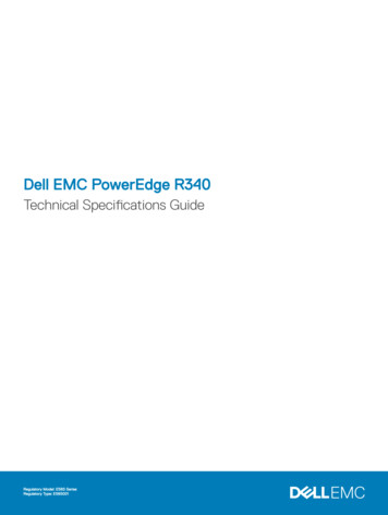
Steps1Go to Dell.com/qrl and navigate to your specific product or2Use your smartphone or tablet to scan the model-specific Quick Resource (QR) code on your system or in the Quick ResourceLocator section.Quick Resource Locator for Dell EMC PowerEdge R340systemFigure 11. Quick Resource Locator for Dell EMC PowerEdge R340 systemReceiving automated support with SupportAssistDell EMC SupportAssist is an optional Dell EMC Services offering that automates technical support for your Dell EMC server, storage, andnetworking devices. By installing and setting up a SupportAssist application in your IT environment, you can receive the following benefits: Automated issue detection — SupportAssist monitors your Dell EMC devices and automatically detects hardware issues, bothproactively and predictively. Automated case creation — When an issue is detected, SupportAssist automatically opens a support case with Dell EMC TechnicalSupport. Automated diagnostic collection — SupportAssist automatically collects system state information from your devices and uploads itsecurely to Dell EMC. This information is used by Dell EMC Technical Support to troubleshoot the issue. Proactive contact — A Dell EMC Technical Support agent contacts you about the support case and helps you resolve the issue.The available benefits vary depending on the Dell EMC Service entitlement purchased for
The Dell EMC PowerEdge R340 system supports up to two 10/100/1000 Mbps Network Interface Controller (NIC) ports that are located on the back panel. Serial connector specifications The Dell EMC PowerEdge R340 system supports one serial connector on the back panel, which is a 9-pin connector, Data Terminal Equipment (DTE), 16550-compliant.