Transcription
Ultg IFILE COPYREPAIR, EVALUATION, MAINTENANCE, ANDREHABILITATION RESEARCH PROGRAMinofEnsTECHNICAL REPORT REMR-CS-23EVALUATION OF POLYESTER RESIN, EPOXY,AND CEMENT GROUTS FOR EMBEDDINGREINFORCING STEEL BARS INHARDENED CONCRETEbyJ. Floyd BestSingleton Materials Engineering LaboratoryTennessee Valley Authority400 West Summit Hill DriveKnoxville, Tennessee 37902andJames E. McDonaldDEPARTMENT OF THE ARMYWaterways Experiment Station, Corps of Engineers3909 Halls Ferry Road, Vicksburg, Mississippi 39180-61990%ELECTE"FEB 13 1990January 1990Final ReportApproved For Public Release; Distribution UnlimitedDEPARTMENT OF THE ARMYUS Army Corps of EngineersWashington, DC 20314-1000Support Agreement No. WESSC-85-01/TV-66369ACivil Works Research Work Unit 32303Prepared forUnder
The following two letters used a5 part of the number designating technical reports of research publisher? under the Repair,Evaluation, Maintenance, and Rehabilitation (REMR) Research Progr-m identify the problem area under which the reportwas prepared:Problem AreaCSConcrete and Steel em AreaEMElOMElectrical and MechanicalEnvironmental ImpactsOperations ManagementDestroy this report when no longer needed. Do not returnit to the originator.The findings in this report are not to be construed as anofficial Department of the Army position unless sodesignated by other authorized documents.The contents of this report are not to be used foradvertising, publication, or promotional purposes.Citation of trade names does not constitute anofficial endorsement or approval of the use of suchcommercial products.COVER PHOTOS:TOP -Anchor pullout strength testBOTTOM - Creep tests on air-cured specimens
UnclassifiedSECURITY CLASS!FICATION OF THiS PAGEREPORT DOCUMENTATIONPAGEOMNo. 0704o18lb. RESTRICTIVE MARKINGS)a. REPORT SECURITY CLASSIFICATIONnelassifiedZa.3. DISTRIBUTION IAVAILABILITY OF REPORT.ECURITY CLASSIFICATION AUTHORITYApproved for public release; distributionunlimited.2b. DECLASSIFICATION/DOWNGRADING SCHEDULES. MONITORING ORGANIZATION REPORT NUMBER(S)4. PERFORMING ORGANIZATION REPORT NUMBL,'MS)Technical Report REM-CS-236a. NAME OF PERFORMING ORGANIZATION6b. OFFICE SYMBOL(if applicable)SingL-,ton Materials F.ngineeringLaboratory, rVA (See reverse)6c. ADDRESS (City, State, and ZIP Code)400 West Summit Hill Drive(See reverse)Knoxville, TN 37902Tb.8a. NAME OF FUNDING /SPONSORINGOFFICE SYMBOL9. PROCUREMENT INSTRUMENT IDENTIFICATION NUMBER(If applicable)ORGANIZATIONSupport Agreement WESSC-85-OI/TV-66369AUS Army Corps of EngineersState, and ZIP Code)8c. ADDRESS (City,20 Massachusetts Avenue,Washington, DC7a. NAME OF MONITORING ORGANIZATIONUSAEWESStructures Laboratorylb. ADDRESS (City, State, and ZIP Code)3909 Halls Ferry RoadVicksburg, MS 39180-619910. SOURCE OF FUNDING NUMBERSNWPROGRAMELEMENT NO.20314-1000TASKNO.PROJECTNO.WORK UNITACCESSION NO.323031I. TITLE (Include Security Classification)Evaluation of Polyester Resin, Epoxy, and Cement Groutv for Embedding Reinforcing Steel Barsin Hardened Concrete12. PERSONAL AUTHOR(S)Best, J. Floyd; McDonald, James E.13a. TYPE OF REPORT13b. TIME COVERED14. DATE OF REPORT (Year. Month, Day) 115. PAGE COUNT869January 1990FROM Apr 19 5TO Jun 198wFinal report L 4 u-A LIIjJLiu4.LLULLVUr1L aun o a repot7L Di Lne ,o.UL.16. SUPPLEMENTARY NOTATIONRepair, Evaluation, Maintenance, and Rehabilitation (REHR) Research Program. Available fromNational Technical Information Service, 5285 Port Royal Road, Springfield, VA 22161.- 18. SUBJECT TERMS (Continue on reverse if necessary and Lentify by block number),COSATI CODES17.YNT qyTCO1O11Drilling) e('e%-Anchor grouting systems)SUB-GROUPGROUPFIELDPullout strength,Concrete anchors)Creep)Underwater o19., BSTRACT (Continue on reverse if necessary and identify by block number)Rehabilitation of hydraulic structures usually includes removal and replacement ofdeteriorated concrete. Dowels are normally used to anchor the new concrete to the exist igconcrete and to position vertical and horizontal reinforcing steel in the replacement con-,crete. The purpose of this investigation was to evaluate the effectiveness of cement, epoxy,and polyester resin grouts used to embed reinforcing steel bars in hardened concrete under avariety of placing and curing conditions. The following parameters were determined for each(a) physical charactlristics of the grouts,,r(bY effects of temperature and moisturegrout:on early service performance, (c) long-term pullout strength under varying curing conditions,(0) creep strain of grout under sustained loading in both wet an% dry environments' and(e) effects of hole roughness ahd cleanliness on grout performanc/(Continued)20. DISTRIBUTION /AVAILABILITY1:1 UNCLASSIFIED/UNLIMITEDOF ABSTRACTE7 SAME AS APT.220. NAME O1- kESPONSIBLE INDIVIDUALDOForm 1473,JUN 8621. ABSTRACT SECURITY CLASSIFICATIONUnclassified0] DTIC USERSI 2b.TELEPHONE (Include Are&Prevlous editions are obsolete.2oe)c.OFFICE SYMBO LSECURITY CLASSIFICATION OF THIS PAGEUnclassified
UnclassifiedECULITv CLASSIFICATION OF THIS PAGE6a. and c.NAME AND ADDRESS OF PERFORMING ORGANIZATION (Continued).USAEWES, Structures Laboratory, 3909 Halls Ferry Road, Vicksburg, MS19.39180-6199.ABSTRACT (Continued).Beyond I day age, all grouts developed pullout strengths approximately equal to the ultimate strength of the reinforcing-bar anchor when the grouts were placed under dry conditions,regardless of curing conditions. With the exception of the polyester resin grout placed undersubmerged cenditions, pullout strengths were essentially equal to the ultimate strength of theanchor when the grouts were placed under wet or submerged conditions.The overall average pullout strength of polyester resin grout placed and cured under submerged conditions was 35 percent less than the strength of the same grout placed and curedunder dry conditions. The largest reductions in pullout strength, approximately 50 percent,occurred at ages of 6 months and 16 months. Also, the overall average pullout strength ofpolyester resin grout placed and cured under submerged conditions was approximately one-thirdless than the strength of epoxy and cement grout placed under wet and submerged conditions,respectively, and cured under submerged conditions.Polyester-resin-grouted anchors exhibited significantly higher creep than that exhibitedby epoxy- and cement-grouted anchors under both wet and dry conditions. Consequently, creepdata should be considered in the selection of an anchorage grout where the frictional resistance and bond between the surfaces of the two masses to be anchored together are important.Extra care should be taken to clean all percussion-drilled holes prior to grouting, particularly when epoxy or cement grout is to be used as the anchoring material.Although the epoxy grout performed well in these tests when placed in wet holes, it shouldbe noted that the manufacturer does not recomend placement under submerged conditions. Thisrecommendation and the significantly reduced pullout capacity of polyester resin grout undersubmerged conditions appear to make cement grout the logical choice for submerged applications,UnclassifiedSECURITY CLASSIFICATION OF THIS PAGE
PREFACEThe study reported herein was authorized by Headquarters, US Army Corpsof Engineers (HQUSACE), under Civil Works Research Work Unit 32303, "Application of New Technology to Maintenance and Minor Repair," for %hichMr. James E. McDonald is Principal Investigator.This work unit is part ofthe Concrete and Steel Structures Problem Area of the Repair, Evaluation,Maintenance, and Rehabilitation (REMR) Research Program sponsored by HQUSACE.Mr. Jesse A. Pfeiffer, Jr., is the REMR coordinator in the Directorate ofResearch and Development, HQUSACE.The Overview Committee at HQUSACE for theRENR Research Program consists of Mr. James E. Crews and Dr. Tony C. Liu.Technical Monitor for this study was Dr. Liu.This study was monitored by the Structures Laboratory, US Army EngineerWaterways Experiment Station (WES) and conducted by the Singleton MaterialsEngineering Laboratory (SME), Tennessee Valley Authority, under SupportAgreement WESSC-85-Ol/TV-66369A.All testing was conducted under the directsupervision of Mr. J. Floyd Best, Supervisor, Concrete and Soils Unit, andunder the general supervision of Mr. William H. Childres, LaboratorySupervisor, SME.The study was performed under the general supervision ofMessrs. Bryant Mather, Chief, Structures Laboratory (SL), WES, and Kenneth L.Saucier, Chief, Concrete Technology Division (CTD), SL, and under the directsupervision of Mr. McDonald, CTD.report.Messrs. Best and McDonald prepared thisProgram Manager for REMR is Mr. William F. McCleese, CTD.The reportwas published by the Information Technology Laboratory, WES, with final edit-ing by Mrs. Cilda Miller.Commander and Director of WES during preparation of this report wasCOL Larry B. Fulton, EN.Technical Director was Dr. Robert W. Whalin.Accosicn ForH1TIS G2.A&#k UnEa.-nctnned/.(%0iJt2ti tcttflA iabillty Codes-val and/orSpsrialDist' i
CONTENTSPagePREFACE.1CONVERSION FACTORS, NON-SI TO Sl (METRIC) UNITS OF MEASURDE1ENT.3PART 1:INTRODUCTION .4Background.4Purpose and Scope.5.PART 11:LABORATORY INVESTIGATION .PART III:TEST RESULT'S.**. 137Physical Characteristics of the Grouts .13Pullout Strength Tests . 22Creep j;ests . *. 27.28Effects of Role Conditions.Conclusions. 30RE FERENCZS .TABLES 1-1633
COWVRSION FACTORS,4O-SI TO SI (MiTIC)UNITS OF MEASUREMENTNon-Sl units of measurement used in this report can be converted to SI(metric) units as follows:MultielyTo Obtain-centipoises0.001pascal-secondscubic feet0.02831685cubic metrescubic yards0.7645549cubic metresFahrenheit degrees5/9Celsius degrees or kelvins*feet0.3048metresfluid ounces0.02957353litresfluid ounces per cubic yard0.0386b0715litres per cubic metrefluid ounces per pound (mass)foot pounds (force)inches65.18961.355818millimetres per kilogramnewton metresmillimetres25.4kips (force)4.448222kilonewtonskips per square inch6.894757megapascalspounds (force) per square inch0.006894757megapascalspounds (mass)0.45359237kilt-gramspounds (mass) per cubic footpounds (mass) per cubic yard*16.018460.5932764kilograms per cubic metrekilograms per cubic metreTo obtain Celsius (C) temperature readings from Fahrenheit (F) readings,use the following formula. C - (5/9)(F-32). To obtain kelvin (K) readings, use: K - (5/9)(F-32) 273.15.3
EVALUATION OF POLYESTER RESIN, EPOXY, AND CEMENT GROUTS FOREDBEDDIG REINFORCING STEEL BARS IN HARDENED CONCRETEPART I:INTRODUCTIONBackground1.Rehabilitation of navigation locks usually includes removal andreplacement of deteriorated concrete on lock walls.Dowels are normally usedto anchor the new concrete facing to the existing concrete walls and co position vertical and horizontal reinforcing steel in the concrete facing.Inmost cases, these dowels are embedded in drill holes using prepackaged polyester resin grouts.Field pullout tests on anchors installed under dry condi-tions indicate this to be a satisfactory procedure.2. Failures of anchors embedded in polyester resin grout under wet conditions have been reported.Prepackaged polyester resin was used in 1976 toembed steel anchor bolts underwater in the stilling basin at Old River ControlStructure (McDonald 1980).These bolts were used to anchor prefabricatedsteel modules -f l/2-in.* steel plate positioned between the downstream row ofbaffles and the end sill.A diver inspection about 8 months following com-pletion of the repairs reported a number of anchors broken flush with themodule plate, flush with the grout, or pulled completely out of the concrete.Additional failures were reported in suhsequent inspections.3.Cement grouted anchors were specified for lock wall stabilization atLock 3, Monongahela River (Krysa 1982).the use of resin-grouted anchors.As an option, the contract allowedThe contractor proposed a hybrid systemusing resin grout within the anchorage length in rock and cement grout withinthe concrete lock wall.The manufacturer of the polyester resin recommended a2-1/4-in.-diam drill hole within the anchorage length for1-3/4-in.-diam cartridge with a 1-1/4-in.-diam bar.hole was used within the lock wall.under wet conditions.on-per mixing of theA 4-1/2-in.-diam drillThe anchors were installed and groutedUsing this procedure resulted in the contractor beingunable to stress 35 anchors in the middle and river walls to the design load.*A table of factors for converting non-SI units of measurement to SI(metric) units is presented on page 3.4
4.A failed anchor was removed from the middle wall and closely exam-ined for any possible explanation of the failures.The general appearance ofthe bar in the anchorage zone indicated the polyester resin grout had notbonded to the bar.The lower 5 ft had a light gray material lodged betweenthe deformations of the bar that appeared to be polyester resin.However,this grout was soft and pliable, and could easily be removed from the bar.Inother reaches of the bar, the grout was not soft, and it was harder to removefrom the bar.The contractor claimed that improper mixing occurred becausethe hole was enlarged due to the caving of the hole in the poor rock.Todetermine if the 2-1/4--in.-diam hole was possibly being enlarged during dr lling, the hole from which the failed anchor was removed was grouted with a reddish grout, and a core boring was taken.The core showed the hole wasconsistently 2-1/4-in. in diameter.5.In the interest of better consistency and progress in the anchorinstallation, the Corps recommended a portland-cement grout system be used toanchor the bars.The contractor began to drill a 4-1/2-in.-diau hole fulllength and used cement grout.stressing length grouted.fewer failures.The anchors were tensioned after 9 days and theThis produced more consistent results and farThis method was used to install approximately one-fourth ofthe anchors on the middle wall and three-fourths of the anchors of the riverwall.Purpose and Scope6.The purpose of this investigation was to evaluate the effectivenessof different types of grouts used to embed reinforcing steel bars in hardenedconcrete under a variety of placing and curing conditions.Such bars arefrequently used as dowels to anchor new concrete to existing concrete whenmaking repairs to locks and dams.7.Since the ambient conditions and construction methods may vary fromsite to site, a program was developed to determine the following parametersfor each grout tested.Phase 1 - Physical Characteristics of the GroutsPhase 2 - Eftects of Temperature and Moisture on Early ServicePerformancePhase 3 - Long-Term Pullout Strength Under Varying Curing Conditions5
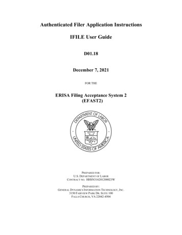
Phase 4 - Creep Strain of Grout Under Sustained Loading in Both Wetand Dry EnvironmentsPhase 5 - Effects of Hole Roughness and Cleanliness on GroutPerformance8.The most commonly used materials for grouting steel dowels in exist-ing concrete have been cement grouts and polyester resin systems.grouts, although more costly, have also been used with success.EpoxySince atleast one epoxy manufacturer now claims his product can be satisfactorilyplaced in damp environments (but not submerged), it was decided to include theepoxy grout with the cement and polyester resin grouts for this investigation.6
PART II:9.LABORATORY INVESTIGATIONA study was initiated in April 1985 to evaluate selected grout sys-tems for embedment of anchors in concrete.Three generic types of grout werea portland cement-water grout with an expansive grout additive andtested:accelerator; a two-component epoxy system mixed with silica sand; and a polyester resin grout preproportioned by the manufacturer and sold in mylarencased cartridges.The cement and epoxy grouts could be pumped into thedrill hole with the bar in the place or under dry conditions could be pouredinto the hole prior to inserting the reinforcing bar.The polyester groutcartridges were first dropped into a drill hole, after which the reinforcingbar was inserted with enough force to break the mylar capsule, and the bar wasthen rotated in the hole at 100 rpm for 30 sec to mix the grout.The manu-facturer of the polyester resin stated that the grout could be placed andcured underwater or in the dry, whereas the epoxy manufacturer did not recommend underwater placement.Instead, they sugg.' ted removal of excess waterfrom the drill hole prior to grouting, then resubmerging the test specimensafter grouting.The grout manufacturer's recomendations were followed inpreparation of test specimens.With the exception of Phase 1, test specimens generally consisted10.of 6- by 18-in. concrete cylinders into which 3/4-in.-diam reinforcing barswere grouted to a depth of 15 in. in a nominal 1-1/8-in.-diam hole.Specimenswere fabricated and stored under both dry and submerged conditions (Figures 1Pullout strength tests were conducted at seven different ages rangingand 2).from 1 day to 32 months.11.Phase 1 testing was structured to determine the physical charac-teristics of the grouts to be evaluated, in addition to the properties of theconcrete and steel reinforcing bars used to fabricate the pullout test specimens.Tensile and elongation tests were conducted on steel reinforcing bars,and compressive strength and modulus of elasticity were determined for theconcrete.properties:Each of the three grouts evaluated were tested for the followinggel time or time of setting, viscosity of the polyester resin andepoxy, tensile strength, compressive strength, modulus of elasticity, bondstrength using the slant-shear method, shrinkagelexpansion, and thermal compatibility with concrete.7
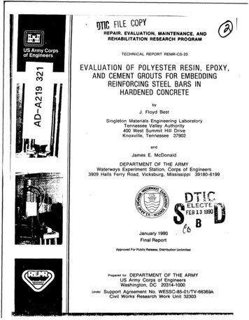
Figure 1.Pullout test specimens stored underdry conditionsFigure 2.Pullout test specimens stored undersubmerged conditions.
12.Phase 2 testing attempted to compare the effects of temperature andmoisture ou the placement and early service performance of the grouts.Pull-out strength tests were conducted at ages of 1, 3, and 7 days for anchorsgrouted under the following conditions.ConditionsCuring ConditionCuringGrout PlacingTemperature,0Fafter GroutingDry70Continuously drySubmerged*70Continuously submergedSibmerged*40Continuously submergedDry70Continuously submergedDry40Continaously submerged*Except for epoxy placed under wet conditions.Exceptions to the above testing parameters were made in the "submerged"placing of the epoxy grout in which the concrete specimen was wet but notsubmerged.Also, the continuousiy submerged curing conditions for both theepoxy and polyester resin grouts placed in dry holes were not begun until thegrout had air cured for 24 hr.Figures 3 and 4 show a typical underwaterinstallation for the polyester resin grout, and Figure 5 illustrates themethod of underwater pressure grouting used for the cement grout.13.Testing for Phase 3 was similar to that for Phase 2, except that nospecimens were cured at 40' F, and testing ages were of longer durations of 1,3, 6, 16, and 32 montbs.Similar to Phase 2, the three specimens for Phase 3were tested ac each age for each curing and placing condition and aresummarized in the following tabulation:Placing Condition*Curing ConditionSubmerged*Continuously submergedSubmerged*Alternating wet-dry (7-day cycles)DryContinuously submergedDryContinuously dryDryAlternating dry-vet (7-day cycles)Except for epoxy placed under wet conditions.9
Figure 3. Placing polyester resingrout cartridge in drill hole undersubmerged specimenFigure 4. Spinning reinforcing barinto submerged drill hole containing grout cartridge10
Figure 5. Pressure grouting withcement grout under submergedconditionsThe same exceptions for Phase 2 apply relating to the wet placing of epoxygrout and the commencement of submerged curing for the epoxy and polyesterresin grouts.14.Phase 4 was confined to measuring the long-term creep strain ofspecimens grouted and cured under both wet and dry conditions.were grouted with each of the three test grouts.Six specimensThree anchors were embeddedin dry, percussion-drilled soles, and the other thrce were(except for the epoxy) also in percussion-drilled holes.mbedded underwaterPullout specimensgrouted dry were subjected to air curing during creep tests while thosegrouted in wet or submerged conditions were subjected to submerged curingduring the tests.The lower end of each cylinder was sawed off to expose thesteel bar extremity so movement at this end could be monitored using a dialextensometer.Approximately I week after grouting, each pullout specimen wassubjected to a sustained load of 60 percent of the yield strength of theii
reinforcing steel bar.Deflections of the anchor at the end of the specimenopposite the loaded end were measured periodically during the 6-month testperiod.Figures 6 and 7 show creep test setups for both dry and submergedcuring.15.Limited testing in Phase 5 evaluated the effects of hole roughnessand cleanliness on 28-day pullout strengths.Vertical holes drilled with bothdiamond-tipped core barrels and rotary percussion bits were grouted underwater (except for the epoxy, for which the specimens were removed and holesdrained of excess water).One-half of the holes were cleaned of debris andcuttings prior to grouting and the remaining one-half were left uncleaned.Pullout tests were then conducted after 28 days of submerged curing.Figure 7.Figure 6. Typical setup for creeptests on air-cured specimens12Creep tests on submergedspecimens
PART III:16.TESTS RESULTSMixture proportions for the concrete used to fabricate the pullouttest cylinders are shown in Table 1 along with proportions used for the cementand epoxy anchor grouts.The polyester grout is preproportioned in mylar car-tridges and needs no blending prior to being placed in the anchor hole.How-ever, since a bulk grout was needed to fabricate specimens for physicalcharacteristics in Phase 1, a sample of polyester resin grout said to containthe same components as the cartridges was obtained from the resin manufacturer.Mechanical properties of the grade 60 reinforcing steel bars, deter-mined in accordance with the American Society for Testing and Materials (ASTM)A 370-86a (ASTM 1987h) are shown in Table 2.Physical Characteristics of the GroutsTime of setting17.Time of setting for the three grout types was determined in accor-dance with ASTM C 807-83 (ASTM 1987d).Table 3.Results of these tests are shown inAs expected, cooler temperatures increased the setting time for thepolyester resin and cement grouts.The epoxy grout manufacturer recommendedtwo different grout products for testing at 70and 40* F, however.TheEpoxy A for use at moderate to warm temperatures had an initial setting timeof 5 hr 15 min at 70F, while Epoxy B set after 1 hr 10 min at 40 F.Sinceinitial and final set occur essentially at the same time for the epoxy andpolyester grouts, final set was determined only for the cement grout.Viscosity18.The viscosity or flowability of both the epoxy and polyester groutswas determined in accordance with ASTM D 2393-86 (ASTM 1987i). these tests, conducted at 70' and 40F are shown in Table 4.Results ofFlowability ofboth grouts was good at 70* F but decreased as expected at 40* F.was still considered quite pourable at 40of syrup. The epoxyF with the approximate consistencyThe polyester resin was thicker being roughly equivalent to honeyin consistency.It was considered moderately pourable at 40* F.Tensile and compressive strength19.All specimens were fabricated in dry molds then placed in the moistcuring room (immediately for the cement, after 24-hr air curing for the epoxy13
and POlYestec) unti.the time Of testing.GomprcssIve strengthconducted in accordancetests werewith ASTM C 39-86(ASTM 1987f) and(ASThM 19 87g).ASTM C 109-86Results Of thesetests are shownwere PerformedinTable5. Tensile testsin accordance withASTM C 307-83 (ASTM 19 8grout (Figure 8)7c) for the cementand ASP 1)638-849(AsTm187e)for the epoxy andgrouts (Figure9). Results ofPolyesterthese tests areshown in TablePolyester grout6. While thehad the highest 28-day compressivestrength, the epoxygroutFigure 8. Tensiletesting of cementgroutFigure 9. Tensiletesting of epoxyand polyester groutp14
was higher in ten.ile strength and also had the highest ratio of tensile tocompressive cube strength at 38 percent.Comparative ratios for the polyesterand cement grouts were approximately 15 and 5 percent, respectively.Ratiosof cube strength to cylinder strength ranged from about 1.2 for the epoxy andpolyester grouts tc about 1.5 for the cement grout.20.To determine if wet or dry curing has a significant effect on co%-pressive strength of the anchor grouts, 2-in. cubes were made for continuousIndividual teststorage in both submerged and laboratory air conditions.results for both types of curing are shown in Table 7.Average test resultsfor specimens cured under submerged conditions are shown in Figure 10.Aftera curing period of 32 months, the submerged-cured polyester specimens averaged37 percent less strength than air-cured specimens while the epoxy experienceda similar reduction of 26 percent (Table 7).Strengths of submerged cementcubes were about 5 percent higher than that of companion air-cured specimens.Modulus of elasticity21.Elastic moduli shown in Table 8 are similar for the three grouttypes, although the epoxy modulus is slightly lower than that of the cementand polyest r grouts.The modulus of elasticity was determined by ASTMC 469-87 (ASTM 1987j), using the electronic compressometer shown in Figure 11.Slant shear bond strength22.Slant-shear bond strength tests, conducted in accordance with ASTMC 882-78 (1983) (ASTM 1987a), were performed on specimens fabricated and cured14-.1-11-x POLYESTER RESINEPOXY- CEMENTa.110010AGE, MONTHSFigure 10.Results of compressive strength tests on submerged specimens15.U. . . .!.' . . . . . . . . . . . . . . .
Figure 11.Typical setup for modulus of elasticityunder both wet and dry conditions.The two bonded cylinder halves were testedat ages up to 28 days using the standard cylinder compression test (Figure 12).23.Test results are shown in Table 9.A significant correlation existed between dry bond strength andtesting age for both the cement and polyester resin grouts.Bond strengthsfor the polyester resin grout were considerably higher than those for thecement grout but lower than the epoxy grout at all testing ages for dry conditions (Figure 13).No significant correlation existed between the dry bondstrength and age of the epoxy grout although there was a trend toward a slightreduction with age.24.A significant correlation existed between wet bond strength andtesting age for the cement and polyester resin grouts.The bond strength ofpolyester resin specimens, fabricated by applying the resin to wet concretesurfaces and immediately submerging in water, decreased from 1,660 psi atI day to 1,270 psi at 28 days age.The wet bond strength of polyester resinspecimens at 28 days was approximately 50 percent less than the dry bondstrength.The cement grout specimens were fabricated by applying the grout towet concrete surfaces and allowing the grout to reach initial set prior toBond strength increased from 610 psi at I day to 2,440 psi atsubmerging.28 days age.25.The epoxy grout specimens were fabricated by applying the epoxy to16
iUFigure 12. Slant-shear bondstrength tests14000.113050EPOXY (OR.300025000. . ." .w.n25O0.zo15005w023571020AGE.DAYSFigure 13. Results of slant-shear bond strength tests ongrouts placed and cured under vet and dry conditions70
wet concrete surfaces, allowed to air cure for 7 days, then submerged untiltested.There was no significant correlation between the wet bond strength ofepoxy grout and testing age, although a trend toward a slight reduction withtime was indicated.Wet bond strengths of the epoxy ranged from 1,640 to2,50 psi with an overall average of 2.100 psi, approximately 40 percent lessthan the average dry bond strength.Shrinkagi/expansion of groutsVolume change of the grouts as determined by the light projection26.method (ASTM C 827-87 (ASTM 1987k) are shown in Table 10.Both the polyesterresin and epoxy grouts showed volume decreases of over 2 percent at initialset while the cement grout with the expansive additive exhibited 0.5 percentexpansion.The shrinkage of the polyester and epoxy grouts is likely due tocooling from peak reaction temperatures.After 2 days of additional aircuring, the polyester resin showed no further shrinkage while the epoxy volumedecreased an additional 2.5 percent and the cement grout volume was reduced byI percent.Since the epoxy generates higher reaction temperatures than thepolyester resin, the additional epoxy shrinkage protably represents furthercoolitg : room temperature while drying shrinkage is the probable cause ofthe cem?:t grout volume reduction.27. Shrinkage of the magnitude measured in these tests is not likely tooccur in field use, since the concrete structure should serve as a heat sinkfor transferring reaction temperatures from the polyester resin and epoxygrouts.The structure should also act as an autogenous curing medium for thecement grout, thus reducing drying shrinkage.Thermal compatibility with concrete28.Table 11 includes an evaluation of the adhesion of a 1/2-in, layerof each grout placed on a concrete t
Ultg IFILE COPY REPAIR, EVALUATION, MAINTENANCE, AND REHABILITATION RESEARCH PROGRAM ofEn s in TECHNICAL REPORT REMR-CS-23 EVALUATION OF POLYESTER RESIN, EPOXY, AND CEMENT GROUTS FOR EMBEDDING REINFORCING STEEL BARS IN HARDENED CONCRETE by J. Floyd Best Singleton Materials Engineering Laboratory Tennessee Valley Authority