Transcription
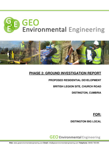
Project Ref: 2019-4032Site Ref: Church Road, DistingtonPHASE 2: GROUND INVESTIGATION REPORTPROPOSED RESIDENTIAL DEVELOPMENTBRITISH LEGION SITE, CHURCH ROADDISTINGTON, CUMBRIAFOR:DISTINGTON BIG LOCALWeb: www.geoenvironmentalengineering.com Email: info@geoenvironmentalengineering.com Telephone: 08456 768 895Page 1
Project Ref: 2019-4032Site Ref: Church Road, DistingtonDOCUMENT CONTROL SHEETReport Ref:2019-4032Report Date:31.01.2020Report Type:PRELIMINARY DRAFT - Ground Investigation Report (GIR)Report Tracking: 06.02.2020 – Preliminary Draft Report IssuedPrepared By:James Brock BSc. MSc. – Geo Environmental Engineer/AssociateAuthorSignature:Checked By:Curtis Evans B.Sc. (Hons), FGS – Geo Environmental Engineer/DirectorClient Title:Distington Big LocalConsultant: Web: www.geoenvironmentalengineering.com Email: info@geoenvironmentalengineering.com Telephone: 08456 768 895Page 2
Project Ref: 2019-4032Site Ref: Church Road, ound Investigation Report53.0Ground Investigation Fieldwork74.0Ground and Groundwater Conditions85.0Exploratory Hole Testing106.0Laboratory Testing127.0Geotechnical Analysis138.0Generic Quantitative Risk Assessment149.0Construction Related Excavations and Off-Site Disposal1810.0Discussions and Recommendations19Appendix I:Site Location PlanExploratory Hole Location PlanProposed Sita Layout PlanAppendix II:Exploratory Hole LogsDCP Calculation SheetsGround Gas Monitoring SheetsAppendix III:Laboratory Test ResultsAppendix IV:GEO Contaminant Analysis SheetsWeb: www.geoenvironmentalengineering.com Email: info@geoenvironmentalengineering.com Telephone: 08456 768 895Page 3
Project Ref: 2019-4032Site Ref: Church Road, Distington1.0 Introduction1.1 BriefGEO Environmental Engineering Ltd (GEO) were commissioned by Distington Big Local, herein referredto as the “Client”, to carry out a ground investigation on land off Church Road in Distington nearWorkington in Cumbria as indicated on the site location plan included in appendix I. The site was formerlyused by the British Legion.The investigation was carried out to determine ground conditions across the site to aid the design offoundations, roads and drainage and to assess the risk to human health and environmental receptorsfrom possible contamination and ground gas.1.2 Site Location and DescriptionThe site, occupying an area of c.0.74ha is located in the central part of Distington, c.5km south east ofWorkington town centre in Cumbria as indicated on the site location plan included in Appendix I. Accessto the site is from Church Road to the north.National Grid Reference:Post Code:300565, 523506CA14 5TG (approximate only)It is understood that the site was previously used by the British Legion, however, the former building inthe north of the site has been demolished and the land cleared. The northern part of the site comprisesa former car park and evidence of the former building (concrete floor slabs). Elsewhere, the land issurfaced with grass which was noted as particularly soft underfoot in places.There was no evidence of any significant contamination sources noted on the site during the walkover.Overall, the site appears generally level with no retaining structures and only minor undulations.Topographical survey data has been provided by the Client which indicates that the lowest part is in thesouth west at c.72.8m AOD, rising gradually to 75.4m AOD in the north west.Existing residential properties and private gardens are present to the north, south and east. A primaryschool is present to the west.1.3 Proposed DevelopmentIt is understood that the site will be developed for residential end use. A proposed site layout has beenprovided by the Client and a copy is included in Appendix I. The plan indicates that the development willcomprise 9 No. bungalows and 39 No. apartments as well as private gardens, communal softlandscaping, access roads, car parking and other associated infrastructure. It is also understood that theClient is considering the use of a soak-away drainage system should the ground conditions provesuitable. Further details relating to the proposed development should be obtained from the Consultant.1.4 Other Reports/StudiesGEO completed a Phase 1: Desk Top Study (DTS) Report, details of which are included below:Phase I Desk Top Study (Preliminary Environmental Risk Assessment), ref: 2019-4032, dated:31.01.2020.It is recommended that the DTS is read in conjunction with this report.Web: www.geoenvironmentalengineering.com Email: info@geoenvironmentalengineering.com Telephone: 08456 768 895Page 4
Project Ref: 2019-4032Site Ref: Church Road, Distington2.0 Ground Investigation Report2.1 Ground Investigation Aims and ObjectivesThe overall objective of this Ground Investigation is to provide information relating to the geotechnicaland environmental properties of the ground and groundwater across the development area in order tofacilitate foundation and drainage design and determine any risks to human health or the surroundingenvironment.2.2 Guidelines, Codes of Practice and Third Part AccreditationsThis report contains information relating to the geotechnical properties of the soils encountered on siteto aid foundation and highway design by a Structural Engineer. The report also incorporates a Level 1Ground Contamination and Ground Gas Risk Assessment for Human Health (Generic Quantitative RiskAssessment – GQRA).The laboratory testing (geotechnical and chemical) was completed by UKAS and MCERTS accreditedlaboratories with details given in Sections 6, with copies of the test reports contained within Appendix III.This Ground Investigation Report has generally been completed in accordance with the followingdocuments:CLR11: Model Procedures for the Management of Land Contamination. DEFRA/EA, 2004.BS10175: 2011: Code of Practice for the Investigation of Potentially Contaminated Sites.BS5930: 2015: Code of Practice for Site Investigations.BS1377: 1990: Methods of test for soils for civil engineering purposes.BS8485: 2015: Code of practice for the design of protective measures for methane and carbondioxide ground gases for new buildings.BS8576: 2013: Guidance on Ground Gas Investigations.CIRIA Report C665: 2015.Eurocode 7 – Geotechnical Design (Part 1: General Rules and; Part 2: Ground Investigation andTesting).UK Specification for Ground Investigation, 2nd Edition. Site Investigation Steering Group, 2011.Effective Site Investigation. Site Investigation Steering Group, 2013.SP1010 Development of Category 4 Screening Levels Main Report, 2014.The LQM/CIEH S4UL’s for Human Health Risk Assessment, 2015.2.3 Ground Investigation Limitations of UseAlthough every effort is made to ensure a full and comprehensive investigation has been completed, itshould always be borne in mind that ground conditions have the potential to vary between exploratoryhole locations and it is recommended that a prudent developer adopt a “watching brief” during theredevelopment works, to ensure that any potential variations encountered are identified and dealt with inan appropriate manner.In addition, this Ground Investigation Report and its contents are limited to the boundaries of the site, asindicated on the Plans in Appendix I. No reliance, copying or use of this report (in part or whole) by anyThird Party is permitted without prior written approval from Geo Environmental Engineering Ltd, withintellectual copyright remaining the sole property of the author. Reliance on the report and its associatedinformation is strictly in accordance with Geo Environmental Engineering Ltd Terms and Conditions,copies of which are available on request.Web: www.geoenvironmentalengineering.com Email: info@geoenvironmentalengineering.com Telephone: 08456 768 895Page 5
Project Ref: 2019-4032Site Ref: Church Road, Distington2.4 Consideration for Residential End UseIt is understood that the site will be developed for residential end use with houses, gardens, car parking,access roads, and other associated infrastructure. Consequently, when considering the intendeddevelopment, the site is considered suitable for assessment using a Level 1 Generic Quantitative RiskAssessment (GQRA).A GQRA provides details of potential future risks to Human Health (proposed end users) from anycontamination which may be identified on site in made ground or natural soils. For the Human HealthRisk Assessment, it is considered that the future residents will be subjected to the greatest exposureperiods and consequently the most risk. Therefore, in accordance with current guidance and legislationa CLEA end use classification of residential has been considered most appropriate.Web: www.geoenvironmentalengineering.com Email: info@geoenvironmentalengineering.com Telephone: 08456 768 895Page 6
Project Ref: 2019-4032Site Ref: Church Road, Distington3.0 Ground Investigation Fieldwork3.1 Intrusive Investigation Fieldworks SummaryThe ground investigation works were completed during December 2019. The exploratory holes werelocated across the site to provide general site coverage taking into consideration the locations of buriedutilities and surface obstructions.The exploratory hole location plan is provided in Appendix I.The ground investigation works comprised:3 No. Dynamic (Windowless) Sampling Boreholes (BH01 to BH03) to depths of between c.0.95mand c.4.00m bgl.9 No. Mechanically Excavated Trial Pits (TP01 to TP09) to depths of between c.1.50m andc.1.80m bgl.Gas and groundwater monitoring (3 visits completed to date).3 No. In-situ ground Infiltration Tests (soak away tests).3 No. In-Situ Dynamic Cone Penetrometer (DCP) Tests.In-situ geotechnical testing (Hand Shear Vane Tests and Standard Penetration Tests - SPTs).Site supervision by a suitably qualified and experienced Geo-Environmental Engineer.Laboratory based geotechnical testing.Laboratory chemical screening of soil samples.Level 1 Generic Quantitative Risk Assessment (GQRA) to determine potential groundcontamination and ground gas risks to the proposed end users.The investigation fieldworks were undertaken in accordance with BS5930:1999, BS1377:1990 andEurocode 7 (Part I and II).At each exploratory hole location, the surfacing type, made ground, natural ground and groundwaterconditions were observed, with in-situ testing undertaken and samples recovered. Details of the groundconditions are included on the exploratory hole logs which are included in Appendix II together with otherrelevant ground investigation data (Gas and Groundwater Monitoring results).The results of the in-situ SPT tests are presented on the borehole logs included in Appendix II.The results of the in-situ hand shear vane tests are presented on the trial pit logs which are included inAppendix II.The results of the Dynamic Cone Penetrometer (DCP) tests and the calculated CBR values are presentedin Appendix II.The results of the geotechnical and chemical laboratory results are provided in Appendix III.All depths included in the report are in metres below ground level (m bgl), unless stated otherwise.Web: www.geoenvironmentalengineering.com Email: info@geoenvironmentalengineering.com Telephone: 08456 768 895Page 7
Project Ref: 2019-4032Site Ref: Church Road, Distington4.0 Ground and Groundwater Conditions4.1 GeneralThe following section provides a summary of the ground conditions encountered across the site duringthe investigation. Reference should be made to the exploratory hole logs included in Appendix II fordetailed descriptions of the strata and groundwater conditions.4.1.2 Made Ground and TopsoilMade ground was encountered across the site to depths of between c.0.37m and c.0.75m bgl. Themade ground was predominantly encountered across the northern part of the site associated withthe area of hardstand and the former building, however, sporadic areas of ashy loam (topsoil) wereencountered sporadically across the area of soft landscaping, possible associated with the formerallotments. Elsewhere, topsoil was encountered to depths of between c.0.26m and c.0.37m bgl.Further details are included below:Exploratory holes located within the former car park (TP03 and TP09) encountered asphalt (0.08mthick) overlying angular gravel of aggregate, slag and concrete over relict (buried) topsoil to depthsof between c.0.48m and c.0.68m bgl.Exploratory holes within the vicinity of the former building (BH03, TP04 and TP05) encountered madeground to depths of between c.0.40m and c.0.75m bgl. This comprised gravelly loam with occasionalmixed aggregate, brick, concrete and timber over a granular layer of mixed aggregate, brick, concreteand slate. Occasional relict (buried) topsoil was also encountered. Trial pit TP05 was locatedadjacent to a concrete slab which was present to a depth of c.0.60m bgl.Exploratory holes located across the area of soft landscaping (TP01, 02, 06, 07, 08, BH01 and BH02)encountered sporadic made ground comprising gravelly loam with occasional glass, plastic,concrete, asphalt, clinker, wire and timber, possibly associated with the historical land use (allotmentgardens) and previous site activities. The loamy made ground occasionally appeared similar to thetopsoil (TP08), however, the presence of occasional asphalt and clinker indicated that it is not from anatural source.Topsoil was encountered to depths of between c.0.33m and c.0.40m bgl and comprised dark greybrown sandy gravelly loam with occasional rare fragments of glass.The made ground materials did not appear suitable for re-use within a private garden, however,consideration could be given to re-using the suitable granular fraction beneath roads, hardstand andbuildings where it will not pose a risk to human health.During the investigation, GEO did not identify any visual or olfactory evidence of fuel/oil typecontamination (no staining, odour or free product) or any landfill type waste such as potentiallybiodegradable, decomposable or putrescible materials.4.1.3 Natural Drift DepositsNatural drift deposits were encountered directly beneath the topsoil and made ground in all of theexploratory holes. The drift deposits typically comprised firm, firm to stiff and stiff brown silty, sandy,very gravelly clay with occasional lenses/pockets of sand. This was proved to a maximum depth ofc.3.0m bgl. Occasional soft to firm clay was encountered at shallow depth (less than 1m bgl).Occasional boulders were also noted.Web: www.geoenvironmentalengineering.com Email: info@geoenvironmentalengineering.com Telephone: 08456 768 895Page 8
Project Ref: 2019-4032Site Ref: Church Road, DistingtonHand shear vane tests were carried out where feasible and safe to do so in the trial pits to confirmfield descriptions and aid foundation design. The tests were completed at depths of between c.0.50mand c.1.60m bgl and gave undrained shear strengths of between 60kN/m2 and 100kN/m2 (typicallybetween 70kN/m2 and 80kN/m2), indicative of clays of medium and high strength.In-situ Standard Penetration Tests (SPTs) were completed in boreholes BH01 and BH02 at depthsof between c.1.00m and c.4.00m bgl. The tests gave ‘N’ values of between 12 and 42, indicative ofclays of medium to very high strength. SPT N values of in excess of 50 were recorded at the base ofboreholes BH01 and BH02 indicating refusal (further penetration not possible, probably due toencountering a large cobble of boulder).4.1.4 Solid Geological Deposits (Bedrock)Solid strata/bedrock was not encountered during the ground investigation.4.2 GroundwaterDuring the intrusive ground investigation works, occasional slight seepages of groundwater wereencountered in the trial pits at depths of between c.0.30m and c.1.60m bgl. The ingress appeared tobe associated with perched (trapped) water rather than a continuous shallow groundwater table. Theboreholes were all noted as dry, however, the drilling process can mask slight groundwater ingress.Groundwater monitoring of installations placed in the boreholes has been carried out on 3 No.occasions between December 2019 and January 2020. Standing groundwater levels have beenrecorded between c.0.54m and c.1.07m bgl. Given the ground conditions (stiff clay), it is likely thatthe water has resulted from surface ingress which has been trapped/perched within the boreholesrather than a continuous groundwater table.Based on the results of the ground investigation, significant groundwater ingress is not anticipated.However, it is recommended that allowance be made for some groundwater control measures (i.e.pumping equipment) particularly during wetter periods of the year, as the materials encountered maydeteriorate following exposure to surface water.Web: www.geoenvironmentalengineering.com Email: info@geoenvironmentalengineering.com Telephone: 08456 768 895Page 9
Project Ref: 2019-4032Site Ref: Church Road, Distington5.0 Exploratory Hole TestingIn-situ site testing and monitoring was generally undertaken in accordance with BS5930:1999,BS1377:1990 and Eurocode 7 (Part I and II).5.1 Standard Penetration Tests5.1.1 Standard Penetration Test MethodologyTo determine the relative density and strength of the underlying soils, Standard Penetration Tests (SPT’s)were completed within the boreholes. The test uses a “split spoon” sample tube (external diameter ofc.50mm, internal diameter of c.35mm and a length of around c.650mm) driven from the base of theborehole as it is progressed, usually at c.1.00m spacing’s/intervals.The sample tube is driven by blows of a slide hammer with a weight of c.63.5kg falling over a c.760mmdrop. The sample tube is driven c.150mm into the ground (seating blows) and then the number of blowsneeded for the tube to penetrate each c.75mm increment up to a depth of c.450mm is recorded.The number of blows for the final c.300mm of penetration is referred to as the “standard penetrationresistance” or “N” value, which are presented on the exploratory hole logs adjacent to each sample depth.Where 50 blows are insufficient to advance the test through a c.75mm interval the amount of penetrationafter 50 blows is recorded and the test is referred to as a “refusal”.5.1.2 Standard Penetration Test ResultsIn-situ Standard Penetration Tests (SPTs) were completed in boreholes BH01 and BH02 at depthsof between c.1.00m and c.4.00m bgl. The tests gave ‘N’ values of between 12 and 42, indicative ofclays of medium to very high strength. SPT N values of in excess of 50 were recorded at the base ofboreholes BH01 and BH02 indicating refusal (further penetration not possible, probably due toencountering a large cobble of boulder).The results of the standard penetration tests are presented on the borehole logs which are includedin Appendix II.5.2 Hand Shear Vane TestsHand shear vane tests were carried out where feasible and safe to do so in the trial pits to confirmfield descriptions and aid foundation design. The tests were completed at depths of between c.0.50mand c.1.60m bgl and gave undrained shear strengths of between 60kN/m2 and 100kN/m2 (typicallybetween 70kN/m2 and 80kN/m2), indicative of clays of medium and high strength.The results of the hand shear vane tests are presented on the trial pit logs which are included inAppendix II.5.3 Dynamic Cone Penetrometer Tests (DCP)The Dynamic Cone Penetration (DCP) Test provides a measure of a material’s in-situ resistance topenetration. The test is performed by driving a metal cone into the ground by repeated striking it withan 8kg weight dropped from a distance of 575 mm. The penetration of the cone is measured aftereach blow and is recorded to provide a continuous measure of shearing resistance up to c.0.85mbelow the ground surface. Test results can be correlated to California Bearing Ratio to aid pavementdesign by a Civil Engineer.Web: www.geoenvironmentalengineering.com Email: info@geoenvironmentalengineering.com Telephone: 08456 768 895Page 10
Project Ref: 2019-4032Site Ref: Church Road, DistingtonThe results of the Dynamic Cone Penetrometer tests and the calculations of the equivalent CBRvalues are included in Appendix II (Dynamic Cone Penetrometer Calculation Sheet).It should be borne in mind that the results of the Dynamic Cone Penetrometer tests can be influencedby the coarse content (gravel, cobbles, etc ) within the materials tested, therefore, it is alwaysrecommended that the appropriate CBR value is confirmed by way of plate load testing at formationlevel.5.4 Ground Permeability AnalysisIt is understood that the Client is considering using soak-away style drainage (Sustainable DrainageSystem - SUDs) as part of the proposed development.In order to facilitate the soak-away design, soil infiltration tests were completed in trial pits TP01 to TP03.The tests involved excavating a trial pit to the appropriate depth (c.1.50m to c.1.70m bgl) and partiallyfilling with water. The water level was monitored at regular intervals.During the test, the water level either remained static or rose within the pit, possibly due to the shallowgroundwater ingress. The tests were terminated after a maximum duration of 240 minutes (4 hours).Based on the results of the tests, the ground conditions are not considered suitable for soak-awaydrainage.5.5 Ground Gas MonitoringTo assess the on-site potential for hazardous ground gases (carbon dioxide and methane), the boreholes(BH01 to BH03) were installed with ground gas monitoring wells to facilitate a period of ground gasmonitoring.The boreholes were installed to depths of between c.0.95m and c.4.00m bgl with a 50mm diameter HDPEstandpipe with a bentonite seal for the upper section and a gravel surround for the remainder of the pipe,finished with a plastic end cap and rubber gas bung. The installation details presented on each boreholelog in Appendix II.The monitoring and assessment has been completed in accordance with BS8485: 2007: Code of practicefor the characterisation and remediation from ground gas affected developments, CIRIA Report C665,November 2007 and the NHBC Document; Guidance on the evaluation of development proposals on sitewhere methane and carbon dioxide are present, March 2007.As it is the intention of the Client to develop the site for Residential end use, the monitoring of groundgas monitoring must comprise at least 6 No. site visits over a minimum period of 3 No. months.To date, the wells have been monitored on 3 No. occasions between the 17th December 2019 and 15thJanuary 2020, in general accordance with CIRIA C665 (Table 5.5a and 5.5b) using a GA2000 GroundGas Analyser with external flow pod.The results of monitoring are included on the Ground Gas Monitoring Record Sheets included inAppendix II. The ground gas risk assessment is presented in Section 8.5 of this report.3 No. additional gas monitoring visits are planned.Web: www.geoenvironmentalengineering.com Email: info@geoenvironmentalengineering.com Telephone: 08456 768 895Page 11
Project Ref: 2019-4032Site Ref: Church Road, Distington6.0 Laboratory Testing6.1 Geotechnical TestingGeotechnical testing was completed in general accordance with BS1377:1990: Part 1 to 4 by thefollowing UKAS and MCERTS accredited laboratory:Professional Soil Laboratories (PSL) of Doncaster, Yorkshire.Samples of the natural drift deposits recovered from the exploratory holes at depths of between c.1.00mand c.1.50m bgl were subjected to tests to determine the moisture content and liquid and plastic Limits.6.2 Chemical Screening6.2.1 Determination of pH and Water-Soluble SulphateIn order to determine the correct concrete classification for buried structures (foundations), laboratorytesting was undertaken for pH and water-soluble sulphate (SO4) on the following samples: 3 No. samples of topsoil (0.20m bgl)5 No. samples of made ground (c.0.10m to c.0.30m bgl)3 No. samples of natural drift deposits (c.1.00m to c.1.50m bgl)The testing was completed in general accordance with BS1377:1990: Part 1 to 4 by the following UKASand MCERTS accredited laboratory:Chemtech Environmental Testing of Stanley, County Durham.Derwentside Environmental Testing Services Limited (DETS) of Consett, County Durham.The results of the testing are summarised in section 10 and presented in the Chemtech report (ref: 83238)and DETS report (20-00214), contained in Appendix III.6.2.2 Contamination Testing for Human HealthTo enable the completion of a Level 1 Generic Quantitative Risk Assessment (GQRA) for Human Health,the following samples were scheduled for chemical laboratory screening: 3 No. samples of topsoil (0.20m bgl)5 No. samples of made ground (c.0.10m to c.0.30m bgl)The samples were subjected to analysis at Chemtech Environmental Testing of Stanley, County Durhamwhich is UKAS and MCERTS accredited.Potential Contaminants of Concern (PCOC’s) have been determined for the development area based onthe descriptions of the materials encountered within the exploratory holes as indicated below:Inorganic Soil Suite (Human Health Risk Assessment): Metal and Metalloids, Cyanide,Asbestos and Total Organic Carbon.Organic Soil Suite (Human Health Risk Assessment): Speciated Polycyclic AromaticHydrocarbons (PAH – USEPA 16).The full catalogue of soil screening results and test detection limits can be seen in the Chemtech report(ref: 83238) contained in Appendix III.Web: www.geoenvironmentalengineering.com Email: info@geoenvironmentalengineering.com Telephone: 08456 768 895Page 12
Project Ref: 2019-4032Site Ref: Church Road, Distington7.0 Geotechnical Analysis7.1 Testing for Moisture Content, Liquid and Plastic Limits3 No. samples of the natural clay deposits recovered from the exploratory holes at depths of betweenc.1.00m and c.1.50m bgl were scheduled for classification tests to determine their moisture content, liquidand plastic limits. The results of the testing are contained in the PSL report (ref: PSL19/7765) presentedin Appendix III and summarised below.Natural moisture contents of 14% and 22% were observed with liquid limits between 36% and 47% andplasticity indices of between 19% and 26% being recorded. The results indicate clays of intermediateplasticity and a medium volume change potential.Web: www.geoenvironmentalengineering.com Email: info@geoenvironmentalengineering.com Telephone: 08456 768 895Page 13
Project Ref: 2019-4032Site Ref: Church Road, Distington8.0 Generic Quantitative Risk Assessment (GQRA)8.1 Methodology for Assessing Risks to Human HealthWithin the UK, the current framework for assessing potential ground contamination is utilising theContaminated Land Exposure Assessment (CLEA) model as set out by the Department of theEnvironment, Farming and Rural Affairs (DEFRA). This comprises the established pollutant linkagemodel of Source – Pathway – Receptor. For a risk to be present to the proposed end user (Receptor)there must be an identified Source and a plausible Pathway. Where one or more of the links are missingthen risk is negated. In order for the land to be classified as contaminated under Part IIa of theEnvironmental Protection Act (EPA) 1990 all three elements of the pollutant linkage must be present.A human health risk assessment can completed using the contamination levels recorded in the soils bycomparing the values against published Generic Assessment Criteria (GAC), such as CLEA SoilGuideline Values (SGV’s), Category 4 Screening Levels (C4SLs), Land Quality Management (LQM),Chartered Institute of Environmental Health (CIEH) S4UL Values and Atkins ATRISKSOIL Soil ScreeningValues (SSV’s). The guidelines are generally based on three main land uses as outlined below:Residential(with or without plant uptake)AllotmentsCommercialWhere these land uses are not deemed appropriate, other land use values can be considered with theDEFRA C4SLs, LQM S4UL’s values and the ATRISKSOIL SSV’s (i.e. parks/playing fields/Public OpenSpace). Alternatively, it is possible to determine site specific intervention values as part of a DetailedQuantitative Risk Assessment (DQRA).It is anticipated that the proposed development will incorporate a residential development with privategardens and areas of communal soft landscaping. Therefore, for the purposes of this basic Human Healthground contamination risk assessment, the maximum site recorded values for the soil samples havebeen compared to GAC for a CLEA end use classification of: Residential with plant uptake end use todetermine if a potential risk is present to the proposed end users.Contaminant Analysis Sheets that include the results of the relevant Human Health Risk Assessment andthe Generic Assessment Criteria (GAC) values are presented in Appendix IV.Web: www.geoenvironmentalengineering.com Email: info@geoenvironmentalengineering.com Telephone: 08456 768 895Page 14
Project Ref: 2019-4032Site Ref: Church Road, Distington8.2 Human Health Risk Assessment – Comparison with Guidance Levels8.2.1 Generic Contaminants – SoilThe maximum concentration values for each inorganic analyte have been compared to the most relevantpublished Generic Assessment Criteria (GAC) as part of the Maximum Value Test. The GAC have beenselected using the following guidance documents:LQM CIEH S4UL 2014 (Residential with Plant Uptake End Use).Category 4 Screening Levels C4SL (Residential with Plant Uptake End Use).Atkins ATRISK Soil Screening Values (Residential with Plant Uptake End Use)As discussed in section 8.1, the contaminant concentrations have been assessed against GAC for aresidential with plant uptake end use as it is anticipated that the proposed development will incorporateprivate gardens and areas of communal soft landscaping.Based on the results of the contaminant analysis sheet contained in Appendix IV none of the inorganiccontaminant concentrations exceed the assessment criteria and as such do not pose a risk to humanhealth.In addition, phytotoxic elements (copper, nickel and zinc) are within the acceptable limits for topsoil(BS3882: Specification for Topsoil, 2015).8.4.2 Organic Contaminants – SoilThe maximum concentration values for the organic analytes tested
BS10175: 2011: Code of Practice for the Investigation of Potentially Contaminated Sites. BS5930: 2015: Code of Practice for Site Investigations. . In-Situ Dynamic Cone Penetrometer (DCP) Tests. In-situ geotechnical testing (Hand Shear Vane Tests and Standard Penetration Tests - SPTs). Site supervision by a suitably qualified and experienced .

