Transcription
HIGH POWERWALL CONNECTORINSTALLATION GUIDE
INFORMATION ABOUT YOUR TESLA VEHICLE IS AVAILABLE AT:www.teslamotors.com/myteslaTo contact Tesla call 1-877-79TESLA (1-877-798-3752)For Roadside Assistance call 1-866-99TESLA (1-866-998-3752) 2012 TESLA MOTORS, INC. All rights reserved.All information in this document and all MODEL S software is subject to copyright and other intellectual property rights of Tesla Motors, Inc. and its licensors. This material may notbe modified, reproduced or copied, in whole or in part, without the prior written permission of Tesla Motors, Inc. and its licensors. Additional information is available upon request.TESLA MOTORS , TESLA ROADSTER , , , , and MODEL S are registered trademarks of Tesla Motors, Inc. in the United States. TESLA is a trademark ofTesla Motors, Inc. in the United States and other countries. All other trademarks contained in this document are the property of their respective owners and their use herein does notimply sponsorship or endorsement of their products or services. The unauthorized use of any trademark displayed in this document, the High Power Wall Connector or on the vehicleis strictly prohibited.
SAVE THESE IMPORTANT SAFETY INSTRUCTIONSThis document contains important instructions and warnings that must be followedwhen installing and maintaining the High Power Wall Connector.WARNINGS:The High Power Wall Connector must be grounded through a permanent wiring system or an equipment grounding conductor.Do not install or use the High Power Wall Connector near flammable, explosive, harsh, or combustible materials, chemicals, or vapors.Turn off input power at the circuit breaker before installing or cleaning the High Power Wall Connector.Use the High Power Wall Connector only within the specified operating parameters.The High Power Wall Connector is designed only for charging a Tesla vehicle (excluding Tesla Roadster). Do not use it for any other purpose or with any other vehicle or object.Do not use or stop using the High Power Wall Connector if it is defective, appears cracked, frayed, broken or otherwise damaged, or fails to operate.Do not attempt to open, disassemble, repair, tamper with, or modify the High Power Wall Connector. The High Power Wall Connector is not user serviceable. Contact Tesla for any repairs.Do not use the High Power Wall Connector when either you, the vehicle or the High Power Wall Connector is exposed to severe rain, snow, electrical storm or other inclement weather.When transporting the High Power Wall Connector, handle with care and do not subject it to strong force or impact or pull, twist, tangle, drag or step on the High Power Wall Connector to protectfrom damage to it or any components.Protect the High Power Wall Connector from moisture, water, liquid and foreign objects at all times. If any exist or appear to have entered, damaged or corroded the High Power Wall Connector,do not use the High Power Wall Connector.Do not touch the High Power Wall Connector’s end terminals with sharp metallic objects, such as wire, tools or needles.Do not forcefully fold any part of the High Power Wall Connector or damage it with sharp objects.Do not insert foreign objects into any part of the High Power Wall Connector.Do not use the High Power Wall Connector when a vehicle cover is on the vehicle.Use of the High Power Wall Connector may affect or impair the operation of any medical or implantable electronic devices, such as an implantable cardiac pacemaker or an implantablecardioverter defibrillator. Check with the electronic device manufacturer concerning the effects that charging may have on such electronic device before using the High Power Wall Connector.CAUTIONS:Incorrect installation and testing of the High Power Wall Connector could potentially damage either the vehicle’s Battery and/or the High Power Wall Connector itself. Any resulting damage isexcluded from the warranty for both the vehicle and the High Power Wall Connector.Do not operate the High Power Wall Connector in temperatures outside its operating range of -22 F to 113 F (-30 C to 45 C).Ensure that the charge station’s supply cable is positioned so it will not be stepped on, tripped over, or subjected to damage or stress.Do not use cleaning solvents to clean any of the High Power Wall Connector’s components. The outside of the High Power Wall Connector, the charging cable, and the connector end of thecharging cable should be periodically wiped with a clean dry cloth to remove accumulation of dirt and dust.Be careful not to damage the circuit board when removing the power entry knock-out.P/N: 1018667-00-A REV: 1.00
PRODUCT SPECIFICATIONSAll specifications and descriptions contained in this document are verified to be accurate at the time of printing. However, because continuousimprovement is a goal at Tesla, we reserve the right to make product modifications at any time.FCC DECLARATION OF CONFORMITYThis device complies with Part 15 of the FCC rules. Operation is subject to the following two conditions: (1) This device may not cause harmfulinterference, and (2) this device must accept any interference received, including interference that may cause undesired operation.Radio and Television InterferenceThe equipment described in this manual has been designed to protect against Radio Frequency Interference (RFI). However, there are some instanceswhere high powered radio signals or nearby RF-producing equipment (such as digital phones, RF communications equipment, etc.) could affectoperations.If interference to your High Power Wall Connector is suspected, relocate or turn off nearby electrical appliances during charging, before contacting Teslafor assistance.Important!Changes or modifications to this product not authorized by Tesla could void the FCC compliance.
SPECIFICATIONS . 2FEATURES . 3SERVICE WIRING - NORTH AMERICA .4SERVICE WIRING - EUROPE .6INSTALLATION. 7IMPORTANT !READ THIS ENTIRE DOCUMENT BEFORE INSTALLINGOR USING THE HIGH POWER WALL CONNECTOR.FAILURE TO DO SO OR TO FOLLOW ANY OF THEINSTRUCTIONS AND WARNINGS IN THIS DOCUMENTCAN RESULT IN FIRE, ELECTRICAL SHOCK, SERIOUSINJURY OR DEATH.THE HIGH POWER WALL CONNECTOR MUST BEINSTALLED BY A QUALIFIED ELECTRICIAN, AND INACCORDANCE WITH LOCAL ELECTRICAL CODES ANDORDINANCES.TOOLS REQUIRED.7OVERVIEW OF STEPS .7STEP ONE - CHECK BOX CONTENTS .7STEP TWO - INSTALL WALL BRACKET . 8STEP THREE - PREPARE CONNECTOR FOR INSTALLATION . 9STEP FOUR - MOUNT CONNECTOR .10STEP FIVE - CONNECT WIRING.10STEP SIX - RECONNECT RIBBON CABLE . 11STEP SEVEN - CONFIRM A SUCCESSFUL INSTALLATION. 11STEP EIGHT - SET OPERATING CURRENT. 12STEP NINE - SECURE COVER AND POWER UP .13HIGH POWER WALL CONNECTORCONTENTSTROUBLESHOOTING . 14MAINTENANCE AND REPAIR .15For information on how to charge your Tesla vehicle, refer to the documentationprovided with your vehicle.1
HIGH POWER WALL CONNECTORSPECIFICATIONSThe maximum rating for the High Power Wall Connector is 20 kW or 80 amps at 240 volts. Your vehicle will charge from 200 to 240 volts.Voltage and Wiring120V ABOVE GROUND (common in North America)230V ABOVE GROUND (common in Europe, Asia, and Australia)240V AC single-phase: L1, L2, and safety ground230V AC single-phase: LINE, NEUTRAL, and EARTH.208V AC 3-phase, wye-connected: Any 2 phases, and safety ground.240V AC 3-phase, delta-connected: With center tap on one leg, use only thetwo phases on either side of the center tap. The two phases must both measure120V AC to ground. Do not use the third leg (208V “stinger”).CurrentFrequencyMaximum 100A Circuit Breaker.The maximum current for charging the vehicle is 80A or 20 kW.At 240V, this will be 19 kW maximum.Maximum 100A Circuit Breaker.The maximum current for charging the vehicle is 80A or 20 kW.At 230V, this will be 18 kW maximum.60 Hz50-60 HzCable LengthApproximately 25’ (7.6 m)Bracket DimensionsHeight: 15” (382 mm)Width: 6.22” (158.2 mm)Depth: 3.7” (96 mm)SPECIFICATIONSWeight (including bracket)220 lbs (9 kg)Operating Temperature-22 F to 113 F-30 C to 45 CStorage Temperature-58 F to 185 F-50 C to 85 CEnclosure RatingType 3RIP 44Agency ApprovalsUL, FCC Part 15EN, IEC
For the fastest charging, using a circuit breaker rated for 100 amps isrecommended. In certain home or office locations, this level of power isn’treadily available. Therefore, you can adjust the current setting on the HighPower Wall Connector for 40 to 100 amp breakers (see page 12).SELF-MONITORING AND RECOVERYThe High Power Wall Connector has a ground monitoring circuit thatcontinuously checks for the presence of a safe ground connection andautomatically recovers from faults. Manual testing and resetting is notrequired.Temporary problems such as ground faults or utility power surges areovercome automatically. If a GFCI fault occurs that interrupts charging,the High Power Wall Connector automatically tries to clear the fault andre-attempt charging.POWER OUTAGESIf a power outage occurs, the High Power Wall Connector automaticallyresumes charging when power is restored. If the charging cable is pluggedinto the vehicle when power is restored, the lights blink and the unit doesnot energize the charging cable for approximately 15 seconds to 3 minutes.This prevents the utility grid from experiencing a large surge when poweris restored, allowing the vehicle to begin drawing current at random times,rather than all at once.FEATURESIf the problem is immediately sensed a second time, the High Power WallConnector waits 15 minutes before trying to charge. This process repeatseight times and if all attempts are unsuccessful, power is removed andno further attempts are made. In this case, you’ll see a red error lighton the front panel (refer to the troubleshooting table on page 14). It isrecommended that when you see a red error light, you power off the HighPower Wall Connector and then power it back on again.HIGH POWER WALL CONNECTOROPTIONAL CIRCUIT RATINGS3
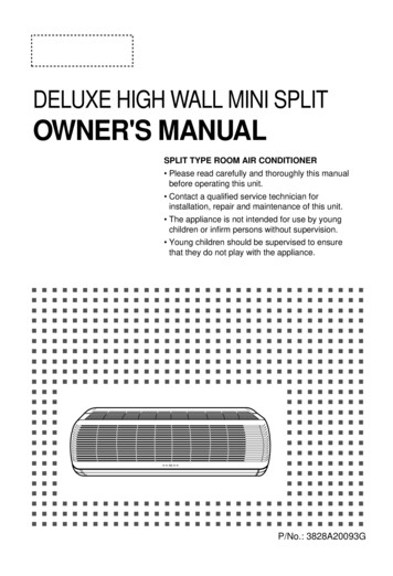
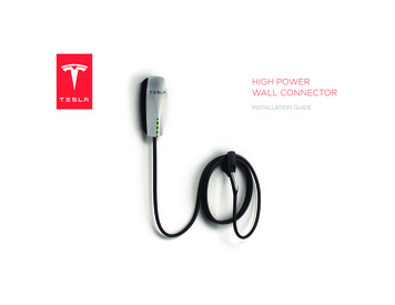
HIGH POWER WALL CONNECTORSERVICE WIRING - NORTH AMERICA4120V ABOVE GROUNDGround connectionFor most branch circuits of 100A, use 3 AWG (26.7 mm2), 167 F (75 C)copper wire. Ground wiring can be a maximum of 4 AWG. If your groundwiring does not fit into the bus, use a wire nut or other suitable connectionmethod. For installations less than 100A, use conductors that are sizedaccording to local electrical codes.Always connect the Neutral at the service to Earth ground. Ground faultprotection is not possible unless the Neutral (center tap on the servicetransformer) is connected to an Earth ground.Run 1” (25 mm) conduit on the left side of a wall stud. The conduit fitsinto the opening on either the back or the left side of the High Power WallConnector as described on page 10.The service connections described next are primarily used in NorthAmerica. For service connections used in Europe and Australia(sometimes known as “TT Power Grid”), refer to page 6.Only three wires are connected, but care must be taken that the servicetransformer secondary connection is definitely known, and that the threewires from the main circuit breaker panel are correctly connected andlabeled. The illustrations shown are the most commonly used wiringformats.NOTE: The L1, L2, and GND outputs labelled on the illustrationscorrespond to the inputs on the High Power Wall Connector.If Ground is not provided by the electrical service, you must install agrounding stake nearby. The grounding stake must be connected to theground bar in the main breaker panel, and Neutral connected to Ground atthat point.WARNING: Follow local electrical codes when installing the grounding stake.220/240V Single PhaseL1120VNEUTRAL(NOT USED)WARNINGS:The High Power Wall Connector is a single-phase device. Do not connect all 3 phasesof a 3-phase feed.Before installing the High Power Wall Connector, identify the type of utility serviceconnection available on site. If you are unsure about the type of connection available atthe service panel, consult the local utility company, or contact Tesla for assistance.240V120VL2CAUTIONS:The two phases used must each measure 120V to Neutral. Earth Ground must beconnected to Neutral at only one point, usually at the Service Entry Breaker Panel.GNDIf a 240V 3-phase feed is from a Delta-connected secondary, the leg used must have acenter tap. This center tap must be grounded. Only the two phases on either side of thecenter-tapped leg can be used.All illustrations are for demonstration purposes only.
240V 3-Phase, delta-connected, with center tapon one legWith a wye-connected secondary, any two of the legs can be used toprovide 208V to the High Power Wall Connector. For example, L1 and L2,or L1 and L3, or L2 and L3. The two used phases must each measure120V to Neutral.With the delta connection, one leg must be center tapped, and only thetwo phases on eit
The maximum rating for the High Power Wall Connector is 20 kW or 80 amps at 240 volts. Your vehicle will charge from 200 to 240 volts. 120V ABOVE GROUND (common in North America) 230V ABOVE GROUND (common in Europe, Asia, and Australia) Voltage and Wiring 240V AC single-phase: L1, L2, and safety ground 208V AC 3-phase, wye-connected: Any 2 phases, and safety ground. 240V AC 3