Transcription
UNIT 3 REFRIGERATION EQUIPMENTRefrigeration 3.3.23.3.33.3.43.3.53.4Types of EvaporatorHeat Transfer in EvaporatorsExpansion Devices3.5.13.5.23.5.33.6Types of CondenserAir-cooled CondenserWater Cooled CondenserEvaporative CondenserHeat Transfer in CondensersEvaporators3.4.13.4.23.5Types of CompressorReciprocating CompressorCentrifugal CompressorRotary CompressorScrew CompressorCapillary TubeFloat ValvesThermo-static Expansion ValveSummary3.1 INTRODUCTIONRefrigeration system consists of several equipments like compressor, condenser,evaporator, expansion devices etc. A refrigerant compressor is a machine used tocompress the refrigerant from the evaporator and to raise its pressure so that thecorresponding temperature is higher than that of the cooling medium. The condenser isan important device used in the high pressure side of a refrigeration system. Its functionis to remove heat of the hot vapour refrigerant discharged from the compressor. Theevaporator is used in the low pressure side of a refrigeration system. The liquidrefrigerant from the expansion device enters into the evaporator where it boils andchanges into vapour. The function of an evaporator is to absorb heat from thesurrounding location or medium which is to be cooled, by means of a refrigerant. Thetemperature of the boiling refrigerant in the evaporator must always be less than that ofthe surrounding medium so that the heat flows to the refrigerant. The expansion devicewhich is also known as throttling device, divides the high pressure side and the lowpressure side of a refrigeration system. It is connected between the receiver and theevaporator.ObjectivesAfter studying this unit, you should be able to describe various types of compressor, describe various types of condenser, describe various types of evaporator, and describe various types of expansion device.33
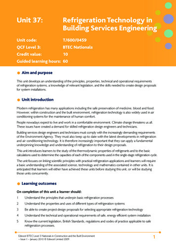
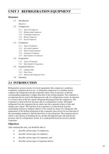
Refrigeration andAir conditioningRefrigeration system consists of different equipments. Individual knowledge of theequipments is required to understand the refrigeration system. The basic principle of therefrigerant equipments and the classification of those equipments are discussed here.3.2 COMPRESSORS3.2.1 Types of CompressorThere are different types of compressors that generally used in industry are,(a)Reciprocating compressor(b)Centrifugal compressor(c)Rotary compressor(d)Screw compressor(e)Scroll compressorThe reciprocating and screw compressors are best suited for use with refrigerants whichrequire a relatively small displacement and condense at relatively high pressure, such asR-12, R-22, Ammonia, etc.The centrifugal compressors are suitable for handling refrigerants that require largedisplacement and operate at low condensing pressure, such as R-11, R-113, etc.The rotary compressor is most suited for pumping refrigerants having moderate or lowcondensing pressures, such as R-21 and R-114; this is mainly used in domesticrefrigerators.Reciprocating CompressorThe compressors in which the vapour refrigerant is compressed by thereciprocating (i.e. back and forth) motion of the piston, called reciprocatingcompressors. These compressors are used for refrigerants which havecomparatively low volume per kg and a large differential pressure, such asammonia, R-12, R-22, etc.Basic Cycle for Reciprocating CompressorThe p-v diagram of a reciprocating compressor is shown in theFigure 3.1 along with the skeleton diagram of the cylinder and pistonmechanism.When the piston is in the extreme left position of the inner dead centre(IDC), the volume occupied by the gas is Vc V3 called clearance volume,i.e. the volume between the piston and cylinder head. As the piston movesoutward, the clearance gas expands to 4, when the pressure inside thecylinder is equal to the pressure at the suction flange of the compressor. Asthe piston moves further, the suction valve S opens and the vapour from theevaporator is sucked in till the extreme right position of the outer deadcentre (ODC) is reached. At this position the volume occupied by the gas isV1. The stroke or swept volume or piston displacement isV p V1 V3 34 D2L4. . . (3.1)
Refrigeration EquipmentFigure 3.1 : Cylinder and Piston Mechanism and P-V Diagram of a Reciprocating CompressorWhere D is the bore or diameter and L is the stroke, i.e. the distance traveledby the piston between IDC and ODC of the cylinder. At 1, the suction valvecloses as the piston moves inwards and the compression begins. At 2, thepressure in the cylinder is equal to the pressure at the discharge flange of thecompressor. A further movement of the piston inward results in the pressurein the cylinder exceeding the condenser pressure. This opens the dischargevalve D and the vapour from the cylinder flows into the condenser till thepiston reaches again the IDC position. Gas equal to the clearance volume Vcremains in the cylinder and the cycle is operated.The work done for compression is given by the cyclic integral of pdV.Hence,23124134W pdV pdV pdV pdV pdV2413 pdV p 2 V3 V2 pdV p1 V1 V4 Area 1-2-3-4 It will be seen that this area is also expressed by the term Vdp . HenceW pdV Vdp m vdpwhere, m is the mass of the suction vapour. Thus, the specific work in areciprocating compressor is given byw vdpVolumetric Efficiency of Reciprocating CompressorVolumetric efficiency is the term defined in the case of positivedisplacement compressors to account for the difference in the displacementin-built in the compressor Vp and actual volume Vs, of the suction vapoursucked and pumped. It is expressed by the ratio v VsVp 3.2Clearance Volumetric EfficiencyThe clearance or gap between the I.D.C. position of the piston and cylinderhead is necessary in reciprocating compressors to provide for thermalexpansion and machining tolerances. A clearance of (0.005L 0.5) mm is35
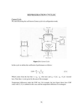
Refrigeration andAir conditioningnormally provided. This space together with the volume of the dead spacebetween the cylinder head and valves, forms the clearance volume. The ratioof the clearance volume Vc to the swept volume Vb is called the clearancefactor C, i.e.,C VcVp 3.3This factor is normally 5 per cent.The effect of clearance in reciprocating compressors is to reduce the volumeof the sucked vapour, as can be seen from Figure 3.1. The gas trapped in theclearance space expands from the discharge pressure to the suction pressureand thus fills a part of the cylinder space before suction begins. Consideringonly the effect of clearance on volumetric efficiency, we have from Figure3.1 , for clearance volumetric efficiency cv V1 V4 Vp Vc V4 VpVp 3.4The volume occupied by the expanded clearance gases before suction beginsis11 p p V4 2 Vc 2 VC p p1 p1 3.5so that p V p CV p CV p 2 p1 cv Vp1 1 p 1 C C 2 p1 3.6Variation of Volumetric Efficiency with Suction PressureAs shown in Figure 3.2 the nature of variation of the p-V diagram of areciprocating compressor with suction pressure for constant dischargepressure. It is seen that with decreasing suction pressure, or increasingpressure ratio, the suction volume V and hence volumetric efficiencydecrease until both become zero at a certain low pressure p’. Thus therefrigerating capacity of a reciprocating compressor tends to zero withdecreasing evaporator pressure.It can be seen from equation 3.6 that the clearance volumetric efficiency willbe zero for a pressure ratio given byp2 1 1 p1 C 36 3.7
Refrigeration EquipmentFigure 3.2: Decrease in Suction Volume in a Reciprocating Compressor withDecreasing Evaporator PressureEffect of Valve Pressure DropsFor the flow of any fluid, the pressure must drop in the direction of flow.Both suction and discharge valves will open only when there is a pressuredrop across them. The effect of these pressure drops on the indicatordiagram of the compressor is shown in Figure 3.3 It is seen that as a result ofthrottling or pressure drop on the suction side the pressure inside thecylinder at the end of the suction stroke is Ps while the pressure at thesuction flange is P1. The pressure in the cylinder rises to the suction flangepressure Pt only after the piston has travelled a certain distance inwardduring which the volume of the fluid has decreased from V p Vc to V1. Assuming the compression index to be n instead of , as the compressionprocess is also polytropic due to heat exchange with cylinder walls andfriction, we have p V1 V p Vc s p1 1n 3.8The expression for volumetric efficiency becomes11nm V p Vc ps Vc p2 V V p1 p1 cv 1 4 VpVp11 p n p m 1 C s C 2 p1 p1 3.9Considering the effect of pressure drop at the discharge valve as well, it canbe shown that the expression for volumetric efficiency is37
Refrigeration andAir conditioning1 p n p cv 1 C s C d p1 p11 m 3.10Figure 3.3: Effect of Valve Pressure DropsOverall Volumetric EfficiencyConsidering the effect of wire-drawing at the valves, polytropiccompression, re expansion, and leakage, we may write the expression for theoverall or total volumetric efficiency as follows11 p n p m v 1 C 2 C d 0.01r p1 p1 3.11The methods of improving the volumetric efficiency include the following:(a)Providing clearance as small as possible,(b)Maintaining low pressure ratio,(c)Cooling during compression,(d)Reducing pressure drops at the valves by designing a lightweight valve mechanism, minimizing valve overlaps andchoosing suitable lubricating oils.Effect of Clearance on WorkThe effect of the clearance volume on the work of compression is mainlydue to the different values of the exponents of the compression andexpansion processes. If the exponents are different, the net work is given by2314W Vdp Vdpn 1m 1 n p2p2 mnm p1V1 1 p1V4 1 3.12 p1 n 1pm 1 1 When the two exponents are equal, i.e. m nn 1 p2 nn W p1Vs 1 p1 n 1 38 3.13
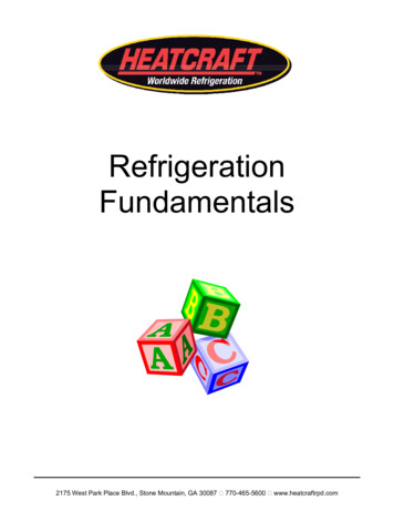
where Vs V1-V4 volume of the vapour sucked. Thus the work is onlyproportional to the suction volume. The clearance gas merely acts like aspring, alternately expanding and contracting. In practice, however, a largeclearance volume results in a low volumetric efficiency and hence largecylinder dimensions, increased contact area between the piston and cylinderand so, increased friction and work.Refrigeration Equipment3.2.2 Centrifugal CompressorA single-stage centrifugal compressor mainly consists of the following fourcomponents as shown in Figure 3.4.(a)An inlet casing to accelerate the fluid to the impeller inlet.(b)An impeller to transfer energy to the fluid in the form of increase instatic pressure and kinetic energy.(c)A diffuser to convert the kinetic energy at the impeller outlet intopressure energy (static enthalpy).(d)A volute casing to collect the fluid and to further convert the kineticenergy into pressure energy (static enthalpy).Besides these, there are intercoolers, generally integrated with the casing, in amultistage compressor. The casing is usually made of cast iron and the impeller,of alloy (chrome-nickel) steels. The maximum stress is developed at the root ofthe blades.The diffuser is normally vaneless type as it permits more efficient part loadoperation which is quite usual in any air-conditioning plant. A vaned diffuser willcertainly cause shock losses if the compressor is run at reduced capacity and flow.Figure 3.4: Elements of a Centrifugal CompressorPerformance CharacteristicsThe principal performance curve of a centrifugal machine is the head-flowcharacteristic.With 2 radius of impeller 2 angle of exit at impeller tipC velocity with suffix r for radial, u for tangential and2 for exit angular speed of impeller in rad/su velocity of impeller tip39
Refrigeration andAir conditioningwe may write for the tangential velocity at the exitCu 2 u 2 Cr 2 cot 2 3.14We know that head developed with no pre-whirl is given by,w Cu 2 u 2 3.15form the above two equations we get,w u 2 u 2 Cr 2 cot 2 u 22 u 2 Cr 2 cot 2 r2 r2 Cr 2 cot 22 3.16Thus we find that for a given compressor, for which 2 and β2 are fixed, and arotating with certain speed, the head developed is a straight line function of theradial velocity Cr2. The flow rate a, in turn, is proportional to Cr2, The limitinghead is u 22 which is developed at, Cr2 0, i.e., at zero flow rate. This occurs whenthe impeller is simply rotating in a mass of the fluid with the delivery valveclosed.It is seen that the nature of the characteristic depends on the outlet blade angle β2as follows:Three types of blades are identified. They are backward-curved, radial andforward curved.(a)For backward-curved blades, β2 90 head decreases with flow andhence with Q(b)For radial blades, β2 90 head u 22 const.(c)For forward-curved blades, β2 90 , head increases with flowFigure 3.5: Mollier Diagram of Centrifugal StageFrom the point of view of optimal design, an outlet blade angle of 32 is normallypreferred. A simple design will, however, have radial blades.Figure 3.6 shows the theoretical head-flow characteristic for the three cases ofangle β2. For the case of backward-curved blades, it is a drooping characteristic.40
The actual characteristic can, however, be obtained by considering the followinglosses as shown in Figure 3.6(a)Leakage loss L1 proportional to the head.(b)2C relFriction loss L2 proportional toand hence Q22(c)Refrigeration EquipmentEntrance loss L3 due to turning of the fluid to enter the impeller, beingzero at the design point, which also corresponds to maximumefficiency.Figure 3.6: Performance Characteristic and Losses of a Centrifugal CompressorSurgingConsider A as the point of operation at full load. When the refrigerationload decreases, the point of operation shifts to the left until point B ofmaximum head is reached. If the load continues to decrease to the left of B,say to C, the pressure ratio developed by the compressor becomes less thanthe ratio required between the condenser and evaporator pressure. viz.,pp4 kp1p0Hence some gas flows back from the condenser to the evaporator, thuspkincreasing the evaporator pressure and decreasing p 0 .The point ofoperation suddenly shifts to A. As the refrigeration load is still less, thecycle will repeat itself. This phenomenon of reversal of flow in centrifugalcompressors is called surging. It occurs when the load decreases to below35 per cent of the rated capacity and causes severe stress conditions in thecompressor as a result of hunting.Capacity Control of Centrifugal CompressorsCentrifugal compressors require high tip speeds to develop the necessarypressure ratio. The high tip speed is achieved by employing either a largediameter impeller or high rpm or both. Because of large u2, the velocities ingeneral including the flow velocity C are high. Also, there must he areasonable width of the shrouds to minimize friction and achieve highefficiency. Thus, because of the sufficiently large flow area (diameter D andwidth of shrouds b) required and large flow velocity, the satisfactoryvolume that can be handled by a centrifugal compressor is about 30-60cubic metres per minute. A single centrifugal compressor, therefore, can be41
Refrigeration andAir conditioningdesigned for a minimum capacity approximately of the order of 250 TRwith R 11 and 150 TR with R 113 for the purpose of air conditioning.One of the methods to control the capacity of the compressors is by varyingthe compressor speed through a speed-reduction gear. The decrease in speedresults in an operation on a lower head-flow characteristic giving a lowervolume flow rate corresponding to the same pressure ratio.Capacity can be controlled by the use of variable inlet whirl vanes that arefrequently employed with a constant speed drive. The capacity is varied bychanging the angle at which the gas enters the impeller. The gas then enterswith pre-rotation and this result in a decrease in flow.3.2.3 Rotary CompressorRotary compressors are positive displacement, direct-drive machines. There areessentially two designs of this compressor:(a)Rolling piston type(b)Rotating vane typeFigure 3.7: Rotary CompressorIn the rolling piston type, shown in Figure 3.7(a) the roller is mounted on aneccentric shaft with a single blade, which is always in contact with the roller bymeans of a spring. The theoretical piston displacement isVp H ( A2 B 2 )4 3.17where A and B are respectively the diameters of the cylinder and rolling pistonand H the lenght of the cylinder.In the rotating vane type, as shown in Figure 3.7(b) with four vanes, the rotor isconcentric with the shaft. The vanes slide within the rotor but keep contact withthe cylinder. The assembly of rotor and the vanes is off-centre with respect to thecylinder.In both designs, the whole assembly is enclosed in a housing (not shown in thefigures), filled with oil and remains submerged in oil. An oil film forms the sealbetween the high-pressure and the low-pressure sides. When the compressorstops, this seal is lost and the pressure equalizes.Rotary compressors have high volumetric efficiencies due to negligible clearance.They are normally used in a single stage up to a capacity of 5 TR with R-114.Large rotary compressors are used in low-temperature fields, such as in chemical42
and industrial processing, cold storages and freezing, as high displacement. lowstage or booster compressors at -90 to -l00 C evaporator temperature with R-12,R-22 and ammonia. They are available in l0 to 600 hp sizes with 2 to 120 cubicmetres per minute displacement in one unit.Refrigeration Equipment3.2.4 Screw CompressorRotary screw compressors also belong to the category of positive displacementcompressors machine a rotary compressor essentially consists of two helicallygrooved rotors as illustrated in Figure 3.8 which rotate in a housing.The male rotor consists of lobes and is normally the driving rotor. The femalerotor has gullies and is normally the driven rotor. A four-lobe male rotor willdrive a six-gully female rotor at two-thirds of its speed. At 3600 rpm the numberof compressed gas discharges of a four-lobe rotor will he 4 3600 14,400 perminute.Figure 3.8: Sectional and Side Views of a Screw CompressorAs in the case of other positive displacement machines, there are three basiccontinuous phases of the working cycle, viz., suction, compression and discharge.When the male rotor turns clockwise, an interlobe space between a pair andhousing nearest to the suction end opens and is filled with the gas. There are foursuch pairs to be filled during one revolution in a four-lobe rotor and the suctionperiods overlap one another.When remeshing starts, the volume decreases and the pressure rises. The charge ismoved helically and compressed until the trapped volume reaches the dischargeend. The compression ratio is thus fixed.Further rotation simply empties the rotors of the high pressure gas until the lasttraces of the gas are squeezed out, irrespective of the pressure in the condenser.On completion of the discharge phase, there is no residual gas remaining in therotors. As a result, there is no expansion of clearance gases. The compressor hasno suction and discharge valves.There are leakage paths in a screw compressor mainly across the line of meshbetween the rotors and across the clearance between the rotors and the housing.To eliminate leakage, oil is injected in a number of small jets directed towards themesh. Oil injection also serves the purpose of cooling and lubricating along withthat of sealing the leakage paths.43
Refrigeration andAir conditioningA slide valve, closely following the shape of the rotors is used for capacitycontrol. At full load the valve is closed. At part load, the valve opens enabling areturn flow passage to be formed so that a part of the gas drawn into the interlobespaces can flow back to the suction side.The screw compressor combines many advantageous features of both centrifugaland compressors, along with some of its own. As it is a positive displacementmachine, high pressure refrigerants, such as R-22 and ammonia are used in it. Asit is a high speed rotary machine, a large volume can be handled by it. It is,therefore, found extremely suit able for large capacity low temperatureapplications such as in food refrigeration.Like reciprocating compressors, it has no surging problems. It has small pipedimensions and positive pressures due to the use of high pressure refrigerants.Like centrifugal compressors, it has high compression efficiency, continuouscapacity control, unloaded starting and no balancing problems. Also, thecompressor is suitable for large capacity installations.3.3CONDENSERSThe functions of the condenser are to desuperheat the high pressure gas, condenseit and also sub- cool the liquid.Heat from the hot refrigerant gas is rejected in the condenser to the condensingmedium-air or water. Air and water are chosen because they are naturallyavailable. Their normal temperature range is satisfactory for condensingrefrigerants.Like the evaporator, the condenser is also heat-exchange equipment.3.3.1 Types of CondenserThere are three types of condensers, viz.(a)Air- cooled,(b)Water-cooled and(c)Evaporative.As their names imply, air-cooled condensers use air as the cooling medium,water-cooled condensers use water as the medium and the evaporative condenseris a combination of the above, i.e. uses both water and air.3.3.2 Air-Cooled CondensersThere are two types under this category, viz. (a) natural convection and(b) forced-air type.Natural Convection CondenserAir movement over the surface of condenser tubes is by natural convection.As air comes in contact with the warm-condenser tubes, it absorbs heatfrom the refrigerant and thus the temperature of the air increases. Warm airbeing lighter, rises up and in its place cooler air from below rises to takeaway the heat from the condenser. This cycle goes on. Since air moves veryslowly by natural convection, the rate of flow of heat from the refrigerant toair will be small. Thus a natural convection condenser is not capable ofrejecting heat rapidly. Therefore a relatively large surface area of thecondenser is required. Hence the use of this type of condenser is limited tovery small units such as domestic refrigerators. It, however, requires very44
little maintenance.Refrigeration EquipmentIn the small units, the condenser is fixed at the rear of the refrigeratorcabinets. Generally, steel tubes are used, steel being cheaper than copper.To increase the heat-transfer area, wires are welded to the condenser tubes.These wires provide mechanical strength to the coil as well. In certaindesigns, widely-spaced fins are used. It is necessary to space the fins quitewidely to avoid resistance to free (natural convection) air movement overthe condenser.Still another design is the plate-type. The condenser coil is fastened to aplate. The plate being in contact with the condenser tubes, the surface areaof the condenser is increased. The plate-type condenser is mounted on theback of the refrigerator cabinet with a small gap between the cabinet and theplate. This gap gives an air- flue effect and facilitates better naturalconvection air currents.It is obvious that while locating refrigerators or deep-freezes cabinets with anatural convection condenser fixed on the cabinet, sufficient care should betaken to allow free air movement. Also they should not be near an oven orany warm location.Forced-air Circulation CondenserThis type employs a fan or blower to move air over the condenser coil at acertain velocity. The condenser coil is of the finned type. Fins in such coilsare closely spaced (ranging between 8 and 17 fins per inch). The spacebetween the fins gets choked with dirt and lint. Therefore to obtain optimumcapacity, the fins should be kept clean. For circulating air over thecondenser, fans are mounted on the shaft/pulley of the compressor motor.For bigger-capacity plants a separate motor is used to drive the fan orblower as also for hermetic-compressor units.3.3.3 Water Cooled CondensersThere are three types of condensers which fall under this category:(a)tube-in-tube or double pipe,(b)shell-and-coil, and(c)shell-and-tube.Tube-in-Tube or Double Pipe CondenserIn this type, a smaller diameter pipe inserted inside a bigger diameter pipe isbent to the desired form. Water flows through the inner tube and therefrigerant through the annular space between the two tubes; the flow ofrefrigerant and water being arranged in opposite direction to get themaximum benefit of heat-transfer. Due to the impurities present in water,scale can form on the water-side of the tube which can impede the heattransfer; also muck can settle on the surface. Therefore it becomesnecessary to periodically clean the water tube. But in the tube-in-tubesystem, cleaning is not easy, unless a removable header is provided toconnect all the tubes.45
Refrigeration andAir conditioningFigure 3.9: Schematic Representation of a Two-Pass Water-CooledShell and Tube CondenserShell-and-Coil CondenserIt consists of a welded-steel shell containing a coil of finned tubing. Waterflows in the coil, the refrigerant being in the shell. Since the tube bundle isin the form of a coil, the water-side of the tube cannot be brushed but canonly be cleaned chemically.Shell-and-Tube CondenserFigure 3.9 shows a typical shell-and-tube condenser. This is similar inconstruction to the flooded chiller. A number of straight tubes with integralfins are stacked inside a cylindrical shell, the tube ends expanded into tubesheets which are welded to the shell at both the ends. Intermediate tubesupports are provided in the shell to avoid sagging and rattling of the tubes.Since it is very easy to clean the water-side and also, it can be easilyrepaired, this type of water-cooled condenser is very popular. Sinceammonia affects copper, steel tubes are used for ammonia condensers.Water flows through the condenser water tubes while the refrigerantremains in the shell.Since copper has a high thermal expansion and contraction rate, the tubetends to move back and forth in the tube sheets due to the variations intemperature.To prevent the tubes from getting loose at the rolled ends due to this action,the holes in the tube sheets have small grooves. They are only a fewhundredths of mm deep. When the tube ends are rolled or expanded in thetube-sheet holes, the copper tubes also expand into the grooves, therebyeffectively anchoring the tube ends to the tube sheets and preventingmovement of the tubes at the ends. However the expansion forces can causethe tubes to bow.Removable water boxes are provided at the ends of the condenser tofacilitate brushing of the water tubes.Hot (superheated) refrigerant gas enters at the top of the shell and getscooled (desuperheated) and condensed as it comes in contact with the watertubes. The condensed liquid drains off to the bottom of the shell. In somecondensers extra rows of water tubes are provided at the lower end of thecondenser for sub-cooling the liquid below the condensing temperature.46
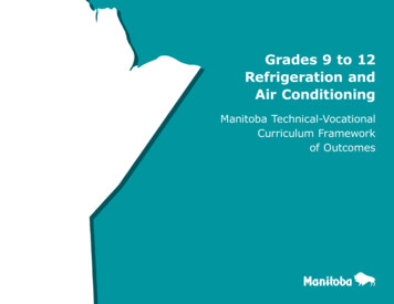
Often the bottom portion of the condenser also serves as the receiver,thereby eliminating the necessity of a separate receiver. However, if themaximum storage capacity (for the refrigerant) of the condenser is less thanthe total charge of the system, a receiver of adequate capacity has to beadded in case the pump down facility is to be provided-such as in ice-plants,cold-storage jobs, etc.Refrigeration EquipmentCare should be taken not to overcharge the system with the refrigerant. Thisis because an excessive accumulation of liquid in the condenser tends tocover too much of the water tubes and reduce the heat-transfer surfaceavailable for condensing the high-pressure gas. This result in increasing thehead pressure and condensing temperature, and excessive overcharge cancreate hydraulic pressures.A fusible plug or safety pressure relief valve is fixed on the shell of thecondenser to protect the high side of the refrigeration system againstexcessive pressures.3.3.4 Evaporative CondenserThese condensers (Figure 3.10) have some features of both air-and water-cooledtypes. Both air and water are employed as a condensing medium. Water ispumped from the sump of the evaporative condenser to a spray header andsprayed over the condenser coil. At the same time a fan thaws air from thebottom-side of the condenser and discharges it out at the top of the condenser. Aneliminator is provided above the spray header to stop particles of water fromescaping along with the discharge air. The spray water coming in contact with thecondenser tube surface evaporates into the air stream. The source of heat forvaporizing the water is taken from the refrigerant, thereby condensing the gas.The evaporative condenser combines the functions of the water-cooled condenserand the cooling tower and hence occupies less space. Moreover, it needs lesspower than a water-cooled condenser. But the most troublesome point about theevaporative condenser is the difficulty in keeping the surface of the condensercoil clean. The condenser coil being both hot and wet in operation, the dirt carriedalong with the air stream forms a hard layer on the condenser. Scale also forms ahard layer if hard water is used. Once these hard layers are allowed to form, it isnever possible to effectively clean the coil. So the capacity of the condenser getssubstantially affected. Because of this maintenance problem, evaporativecondensers are not much in favour.Figure 3.10: Evaporative Condenser3.3.5 Heat Transfer in Condensers47
Refrigeration andAir conditioningThe heat transfer in a water-cooled condenser is described by the Equation givenbelow
UNIT 3 REFRIGERATION EQUIPMENT Refrigeration Equipment Structure 3.1 Introduction Objectives 3.2 Compressors 3.2.1 Types of Compressor . The reciprocating and screw compressors are best suited for use with refrigerants which require a relatively small displacement and condense at relatively high pressure, such as R-12, R-22, Ammonia, etc.