Transcription
Ascend RefrigerationJimex CorporationService ManualJFD - Full Door Upright Reach-insCovers Ascend Units:JFD-23RJFD-23FJFD-48RJFD-48FJFD-72RUpdated 08/13/08- Page 1 of 46-
Ascend RefrigerationJimex CorporationService ManualJFD - Full Door Upright Reach-insCovers Ascend Units:JFD-23RJFD-23FJFD-48RJFD-48FJFD-72RAscend RefrigerationJimex Corporation1575 Zephyr AvenueHayward, CA -477-3412Web Site: www.ascendmfg.comWeb contact: service@ascendmfg.comUpdated 08/13/08- Page 2 of 46-
NOTE: This manual is intended solely for the use of licensed refrigeration technicians. Anyrepairs or alterations made by any person other than a licensed refrigeration technician may voidunit warranty. The information contained within is believed to be accurate at time of printing andis subject to change without warning. Please check our website for the most up to date serviceinformation. WARNING: Before servicing any electrical component be sure unit is unplugged and there isno power to any component. Always wear proper safety gear, and follow good safety practices.Always reclaim any refrigerant charge in accordance with EPA guidelines. Updated 08/13/08- Page 3 of 46-
Table of Contents1. Exploded Views and Parts List1-1. JFD-23R: Exploded View, Parts and Price List 5 - 81-2. JFD-23F: Exploded View, Parts and Price List . 9 - 121-3. JFD-48R: Exploded View, Parts and Price List 13 - 161-4. JFD-48F: Exploded View, Parts and Price List . 17 - 201-5. JFD-72R: Exploded View, Parts and Price List 21 - 242. Wiring Diagrams2-1.JFD-23R 252-2.JFD-23F 262-3.JFD-48R 272-4.JFD-48F 282-5.JFD-72R 293. Electronic Control, SF-102 - Coolers3-1.Components . 303-2.Electrical Set Up . 313-3.Basic Operation . 313-4.Changing Settings . 313-5.Factory Settings . 323-6.Troubleshooting the SF-102 . 334. Electronic Control, SF-104 - Freezers4-1.Components . 344-2.Electrical Set Up . 354-3.Basic Operation . 354-4.Changing Settings . 354-5.Factory Settings . 364-6.Troubleshooting the SF-104 .375. Installing and Replacing Parts5-1.Opening the top panel . 385-2.Removing the top panel 385-3.Electronic control 385-4.Door switches . 385-5.Evaporator coil cover 395-6Evaporator fan motor . 395-7Defrost heater coil and drain line heater (freezers only) . . 405-8Doors . .405-9Tensioner . 415-10. Gaskets . 415-11 Bottom front grill . 415-12. Condensing assembly 425-13. Shelving . . 426. Troubleshooting, FAQ’s and Tech information6-1.Frequently asked questions . 436-2.Table: Amp draw per component . 446-3.Table: Compressor tech data and running pressures . 456-4.Revision and changes history . 46Updated 08/13/08- Page 4 of 46-
1-1.JFD-23R, Exploded View, Parts and Price ListUpdated 08/13/08- Page 5 of 46-
Updated 08/13/08- Page 6 of 46-
Updated 08/13/08- Page 7 of 46-
Updated 08/13/08- Page 8 of 46-
1-2.JFD-23F, Exploded View, Parts and Price ListUpdated 08/13/08- Page 9 of 46-
Updated 08/13/08- Page 10 of 46-
Updated 08/13/08- Page 11 of 46-
Updated 08/13/08- Page 12 of 46-
1-3.JFD-48R, Exploded View, Parts and Price ListUpdated 08/13/08- Page 13 of 46-
Updated 08/13/08- Page 14 of 46-
Updated 08/13/08- Page 15 of 46-
Updated 08/13/08- Page 16 of 46-
1-4.JFD-48F, Exploded View, Parts and Price ListUpdated 08/13/08- Page 17 of 46-
Updated 08/13/08- Page 18 of 46-
Updated 08/13/08- Page 19 of 46-
Updated 08/13/08- Page 20 of 46-
1-5.JFD-72R, Exploded View, Parts and Price ListUpdated 08/13/08- Page 21 of 46-
Updated 08/13/08- Page 22 of 46-
Updated 08/13/08- Page 23 of 46-
Updated 08/13/08- Page 24 of 46-
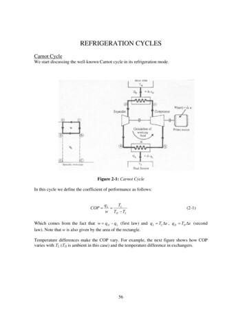
2-1.JFD-23R Wiring DiagramUpdated 08/13/08- Page 25 of 46-
2-2.JFD-23F Wiring DiagramUpdated 08/13/08- Page 26 of 46-
2-3.JFD-48R Wiring DiagramUpdated 08/13/08- Page 27 of 46-
2-4.JFD-48F Wiring DiagramUpdated 08/13/08- Page 28 of 46-
2-5.JFD-72R Wiring DiagramUpdated 08/13/08- Page 29 of 46-
3. Electronic Control, SF-102 - l Set UpBasic OperationChanging SettingsFactory SettingsTroubleshooting3-1. ComponentsThe components of the electronic control for Ascend coolers consist of:(1) Box Sensor(2) SF-102, micro temp control(3) Compressor Relay(4) TransformerUpdated 08/13/08- Page 30 of 46-
3-2. Electrical Set up- The electronic control runs off of 12 volts AC, and sends out 12 volts DC.- 120 V AC is converted to 12 V AC by the transformer before entering the control. The outputfor the compressor (terminal 1 out the back of the control) is 12 V DC. At the compressor relay itis changed to 120 V AC, which powers the compressor.3-3. Basic OperationThe electronic control in Ascend coolers is preset for optimal performance from the factory. Inmost cases the only adjustment that may be desired is changing the set point.Changing the set point:- To change the set point, press and release the “SET” button. A number will now be flashing onthe screen; this number is the set point.- To change the desired set point, simply press the up or the down arrow until the flashingnumber reads the desired set point.- When the desired set point is flashing on the screen there is no need to do anything further. Ina few seconds the flashing set point will be replaced with the solid readout of the current boxtemperature, and the new set point will be stored in the controller’s memory.- The box will now cycle on and off between the value of the set point and the value of the setpoint plus the differential. See Section 3-4 for more information.- Allow up to two hours, depending on product loading and ambient temperatures for the unit toreach the new set point.Initiating a manual defrost:- The default settings for the cooler will automatically initiate an off cycle defrost every 12 hours.However, if at any time a one-time manual defrost is desired, simply press and hold the manualdefrost button for six seconds. There will be an audible beep and the LED indicator for “defrost”will activate.- At default settings the defrost will last for 30 minutes. At this point the defrost LED indicator willchange from solid to indicate “in defrost” to a blinking indicator to indicate that the unit has justcome out of defrost. This blinking will continue for 15 minutes.3-4. Changing SettingsThe electronic control in Ascend coolers is preset for optimal performance from the factory,however if you are installing a replacement control, or wish to change defrost settingsthe default settings will need to be adjusted.- Press and hold the “SET” button for five seconds, until the control emits an audible beep release the “SET” button. The display will now show a blinking “E1.” This is the first of theadjustable settings.- To make a change to any setting, press and release either the up or the down arrow until thedesired setting is reached.- To move to the next setting press and release the “SET” button. If more than ten seconds goby without any buttons being pressed, the control will save all settings, exit the parameter set-upmode, and go back to reading the box temperature.- To either lock or unlock the parameter set-up mode, press and hold the down arrow while thedisplay is reading box temperature. After ten seconds the control will emit an audible beep andUpdated 08/13/08- Page 31 of 46-
the display will read “ON,” indicating that settings E1 through C1 can be changed, or “OFF,”indicating that E1 through C1 cannot be modified.3-5. Factory SettingsE1 The lowest value the end user can choose as the set point.E2 The highest value the end user can choose as the set point.E3 The differential. With a set point of 36 and a differential of 7 , the unit will cool until it reaches36 . At this point, the compressor will then shut off and not come back on until the unitreaches 43 (36 7). The unit will cycle on and off between these two temperatures,maintaining an average box temperature half way between.E4 The compressor start delay is the shortest amount of time between the compressor cycling offand coming back on. It also will delay the compressor from starting when the unit is pluggedin.E5 and E6 will offset the temperatures read by the box and evaporator sensors. Thissetting is rarely used.F1 The maximum amount of time that a defrost can last. A defrost will last for the value set in F1or until the evaporator sensor reads the value set in F3.F2 The defrost interval controls how often the unit goes into defrost. A setting of six correspondsto every six hours, or four times a day. In addition, the first defrost will start an F2 number ofhours after the unit is first plugged in.F3 The defrost termination temperature value will bring the unit out of defrost before the fullamount of time set in F1 has been reached if the evaporator sensor ever reaches the valueset in F3.F4 The display during defrost. A setting of “00” will show the current box temperature as it risesduring a defrost, while a setting of “01” will lock in the last temperature value before thedefrost began.F5, F6, F7, F8 and F9 are advanced settings and are advised not to be changed.C1 The temperature display units. “00” for Celsius, “01” for Fahrenheit.SF-102 Solid Door CoolerFactory nLow set limit, High set limit, Differential, Comp. start delay, minutesBox temp. offset, Evap temp. offset, Max. defrost duration, minutesDefrost interval, hoursDefrost termination, Display during defrostFan operation functionDraining timeFan restart after defrostWhen F7 00When F7 01Temperature unitsUpdated 08/13/08- Page 32 of 46-Setting364573003012681140601
3-6. Troubleshooting the SF-102If the unit is not cooling:Is the compressor LED indicator on?- If the set point is higher than the box temperature, the compressor will not come on.If the compressor LED indicator is on, but the compressor is not:- If the box was just plugged in, there will be a compressor start delay (setting E4).- Check for voltage out of terminal one on the back of the control. The voltage should be 12VDC.- Check for voltage at the compressor relay. There should be 120V AC to the compressor.If the compressor LED indicator is on, and there is 120V AC out of the compressor relay:- Check operation of compressor.Is the temperature the box sensor reading the true box temperature?- Ohm out the sensor. The sensor should read 28,000Ω at 32 F and 10,000Ω at 77 F.If the unit is too cold:Is the compressor LED indicator on?- If the set point is lower than the current box temperature, the compressor will stay on until itreaches the set point.If the compressor LED indicator is not on:- Check for voltage out of terminal one on the back of the control. There should not bevoltage if the compressor LED indicator is not lit.- Check for voltage out of the compressor relay. There should not be voltage out of the relaywhen the compressor LED is not lit.Is the temperature the box sensor reading the true box temperature?- Ohm out the sensor. The sensor should read 28,000Ω at 32 F and 10,000Ω at 77 F.If the unit is building up ice:Are the defrost settings (F1-F9) set to factory settings?- Check the settings (see 3-3 and 3-4) and reset to factory values if needed.If defrost settings are at factory recommendations:- Verify gasket seals, and product moisture levels.- If needed, change the frequency or duration of the defrost cycle. Settings F1 - F3 can bechanged, call factory for recommendations.Updated 08/13/08- Page 33 of 46-
4. Electronic Control, SF-104 - al Set upBasic OperationChanging SettingsFactory SettingsTroubleshooting4-1. ComponentsThe components of the electronic control for Ascend freezers consist of:(1) Box Sensor(2) SF-104 micro temp control(3) Compressor Relay(4) Evaporator Fan Relay(5) Transformer(6) Defrost Relay(7) Evaporator Sensor / Box SensorUpdated 08/13/08- Page 34 of 46-
4-2. Electrical Set up- The electronic control runs off of 12 volts AC, and sends out 12 volts DC.- 120 V AC is converted to 12 V AC by the transformer before entering the control. The outputfor each of the electrical loads (compressor, defrost heaters and fans) is 12 V DC. At therespective relay it is changed to 120 V AC to power the load.The electronic control in Ascend freezers is preset for optimal performance from the factory. Inmost cases the only adjustment that will be desired is changing the set point.4-3. Basic OperationChanging the set point:- To change the set point, press and release the “SET” button. A number will now be flashing onthe screen; this number is the set point.- To change the desired set point, simply press the up or the down arrow until the flashingnumber reads the desired set point.- When the desired set point is flashing on the screen there is no need to do anything further. Ina few seconds the flashing set point will be replaced with the solid readout of the current boxtemperature and the new set point will be stored in the controller’s memory.- The box will now cycle on and off between the value of the set point and the value of the setpoint plus the differential (see 4-4 for more information).- Allow up to four hours, depending on product loading and ambient temperatures for the unit toreach the new set point.Initiating a manual defrost:- The default settings for the freezer will automatically initiate a heated defrost every six hours.However if at any time a one-time manual defrost is desired, simply press and hold the manualdefrost button for six seconds. There will be an audible beep and the LED indicator for “defrost”will activate.- At default settings, the defrost will last for 30 minutes, or until the defrost terminationtemperature is reached (see 4-4). At this point the defrost LED indicator will change from a solidlight to indicate “in defrost,” to a blinking indicator to indicate that the unit has just come out ofdefrost. This blinking will continue for 15 minutes.4-4. Changing SettingsThe electronic control in Ascend freezers is preset for optimal performance from the factory,however if you are installing a replacement control, or wish to change defrost settingsthe default settings will need to be adjusted.- Press and hold the “SET” button for five seconds, until the control emits an audible beep release the “SET” button. The display will now show a blinking “E1.” This is the first of theadjustable settings.- To make a change to any setting, press and release either the up or the down arrow until thedesired setting is reached.- To move to the next setting, press and release the “SET” button.- If more than 10 seconds go by without any buttons being pressed, the control will save allsettings, exit the parameter changing mode, and go back to reading box temperature.- To either lock or unlock the parameter-changing mode, press and hold the down arrow whenthe display is reading the box temperature. After 10 seconds the control will emit an audible beepUpdated 08/13/08- Page 35 of 46-
and the display will read “ON,” indicating that settings E1 through C1 can be changed, or “OFF,”indicating that E1 through C1 can not be modified.4-5. Factory SettingsE1 The lowest value the end user can choose as the set point.E2 The highest value the end user can choose as the set point.E3 The differential. With a set point of 0 and a differential of 10 , the unit will cool until it reaches0 , at this point the compressor will then shut off and not come back on until the unit reaches 10 (0 10). The unit will cycle on and off between these two temperatures, maintaining an averagebox temperature half way between.E4 The compressor start delay is the shortest amount of time between the compressor cycling offand coming back on. It also will delay the compressor from starting when the unit is plugged in.E5 and E6 will offset the temperature’s read by the box and evaporator sensors. This setting israrely used.F1 The maximum amount of time a defrost can last. A defrost will last for the value set in F1 oruntil the evaporator sensor reads the value set in F3.F2 The defrost interval controls how often the unit goes into defrost. A setting of six correspondsto every six hours, or four times a day. The first defrost will start an F2 number of hours after theunit is plugged in.F3 The defrost termination temperature value will bring the unit out of defrost before the fullamount of time set in F1 has been reached if the evaporator sensor ever reaches the value set inF3.F4 The display during defrost. A setting of “00” will show the current box temperature as it risesduring a defrost while a setting of “01” will lock in the last temperature value before the defrostbegan.F5, F6, F7, F8 and F9 are advanced settings and are advised not to be changed.C1 The temperature display units “00” for Celsius, “01” for Fahrenheit.SF-104 Solid Door CoolerFactory nLow set limit, High set limit, Differential, Comp. start felay, minutesBox temp. offset, Evap temp. offset, Max. defrost duration, minutesDefrost interval, hoursDefrost termination, Display during defrostFan operation functionDraining timeFan restart after defrostWhen F7 00When F7 01Temperature unitsUpdated 08/13/08- Page 36 of 46-Setting-102010300306681140601
4-6. Troubleshooting the SF-104If the unit is not cooling:Is the compressor LED indicator on?- If the set point is higher than the box temperature, the compressor will not come on.If the compressor LED indicator is on, but the compressor is not on:- If the box was just plugged in, there is a compressor start delay (setting E4).- Check for voltage out of terminal one on the back of the control. The voltage should be 12VDC.- Check for voltage at the compressor relay. There should be 120V AC to the compressor.If the compressor LED indicator is on, and there is 120V AC out of the compressor relay:- Check operation of compressor.Is the temperature the box sensor is reading the true box temperature?- Ohm out the sensor. The sensor should read 28,000Ω at 32 F and 10,000Ω at 77 F.If the unit is too cold:Is the compressor LED indicator on?- If the set point is lower than the current box temperature, the compressor will stay on until itreaches the set point.If the compressor LED indicator is not on:- Check for voltage out of terminal one on the back of the control. There should not bevoltage if the compressor LED indicator is not lit.- Check for voltage out of the compressor relay. There should not be voltage out of the relaywhen the compressor LED is not lit.Is the temperature the box sensor reading the true box temperature?- Ohm out the sensor. The sensor should read 28,000Ω at 32 F and 10,000Ω at 77 F.If the unit is building up ice:Are the defrost settings (F1-F9) set to factory settings?- Check the settings (see 4-3 and 4-4), and reset to factory values if needed.How long does the unit stay in defrost?- Initiate a manual defrost (see 4.1) and time how long unit stays in defrost.- If the unit comes out of defrost right away (less than a few minutes), it is possible that theevaporator/defrost termination sensor is giving bad values to the SF-104, and terminating thedefrost prematurely. Ohm out the evaporator sensor.Are the defrost heater coil and drain line heater operating correctly?- Initiate a manual defrost and check amp draw on the defrost heater coil circuit (see section6-2 for correct values). Alternatively, drop the evaporator coil cover (see 5-5,) and ohm outthe heater coil (see section 6-2 for correct values).- Drop the evaporator coil cover (see 5-5), and check amp draw, and/or ohm value of drainline heater (see section 6-2 for correct values).If defrost settings are at factory recommendations, and heater coil is operational:- Verify gasket seals, and product moisture levels.- If needed, change the frequency or duration of the defrost cycle. Settings F1 - F3 can bechanged. Call factory for suggestions.Updated 08/13/08- Page 37 of 46-
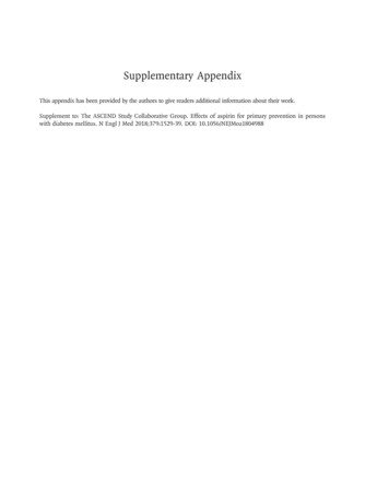
5. Installing and Replacing Parts5-1. Opening the top panel- Remove three Phillipshead screws (two fromJFD-23 units).- The top panel will nowpivot up and out on thehinges connecting it to theof the unit.twotop5-2. Removing the top panelTo remove:- Remove the four bolts that attach the two hinges on the topof the unit to the top panel.- After the two top hinges are disengaged, support the toppanel while removing the screws as directed in 5-1.To install:- Reverse the above installation steps.5-3. Electronic control- To gain accessthe electroniccontrol, simplyfollowinstructions foropening the toppanel asdirected in 5-1.5-4. Door switchesTo remove:- Open top panel, see 5-1 above.- Remove three wires from old door switch.- Remove door switch.To install:- Reverse above directions.Updated 08/13/08- Page 38 of 46-to
5-5. Evaporator coil coverTo remove:- Remove the screws alongtheperimeteroftheevaporator drain pan.- The evaporator drain pancan now be lifted forward andpulled down.- The drain pan will still beattached by the evaporatorfan motor wiring.- Cut the zip ties attachingthe motor wiring to themotors.- Unplug both leads fromeach evaporator fan motor.- Pull the drain lineheater out from the drainline.- The evaporator coilcover is now freelyremovable.To install:- Reverse the above installation steps.NOTE: Be sure the drain line heater does not become bunched up at the start of the drain.5-6. Evaporator fan motorTo remove:- Follow steps 5-5 above to remove the evaporator coil cover.- Remove four screws to free evaporator fan motor fromevaporator coil cover and evaporator fan guard.To install:- Reverse the above directions.Updated 08/13/08- Page 39 of 46-
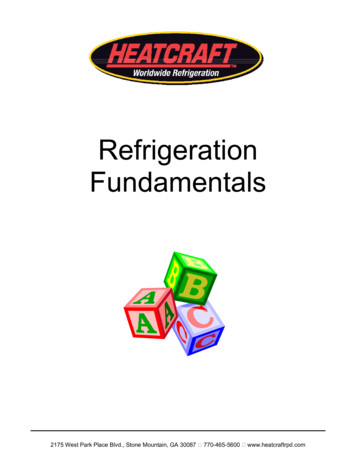
5-7. Defrost heater coil and drain line heater (freezer only)To remove:- Drop the evaporator coil cover, see 5-5 above.- Remove and replace either the defrost heater coil or the drainline heater.- Cut the two wire leads for the replaced component inside thebox, at the heater element.To install:- Remove both the back and top wiring access U-channels.- Push or snake the leads for the replacement heater through theelliptical hole in the back wall of the unit.- Pull the leads tight from the outside back of the box.- Make the replacement connection on the top of the box,discarding the wire leads to the old element.5-8. DoorsTo remove:- Open the top panel, see 5-1.- Remove the screw and washerthat attaches the bracket to thetensioner (white arrow).- While supporting the door,remove the three screws thatattach the top bracket to the unit(black arrows), removing themiddle screw last.- The door will now lift up and offthe bottom hinge.To install:- NOTE: The tensioner works by means of an interior cam. If the door and tensionerare installed incorrectly, the tensioner will act as a spring, trying to open the door, notassist in shutting it. Anytime a door is removed or a tensioner is replaced, care mustbe taken to reinstall the door and tensioner in the correct orientation.- Place the door on the bottom hinge.- With the door in the closed position, attach thetop hinge to the tensioner/door assembly with onePhillips head screw (black arrow at right). Be sure toattach the hinge in the orientation that is as at a 45 angle to with face of the unit. (See picture at right.)- Attach the tensioner/door/upper hinge assembly tothe unit with three Phillips head screw (black arrowsabove), attaching the middle screw first.- Open the door. There should be a tension forcewhich works to close the door.NOTE: Picture is of left-hinged door.NOTE - If the newly-installed tensioner is acting to assist in the opening of the door, it is becauseeither the door or the hinge was installed in the wrong orientation. Remove all screws from theUpdated 08/13/08- Page 40 of 46-
upper hinge and tensioner assembly and re-install. making sure to install with the door closed andthe hinge as pictured above.5-9. TensionerTo remove:- Remove the door asdirected in 5-8.- Remove the twoscrews attaching thetensioner to the door.Withuseofleverage,carefullypry the tensioner outof the door cavity.To install:- Push the new tensioner down into the cavity in the door.- Replace the two screws that were taken out of the old tensioner.NOTE: The tensioner works by means of an interior cam. If the door and tensioner areinstalled incorrectly the interior cam of the tensioner will act as a spring, trying to openthe door, not assist in shutting it. Any time a door is removed, or a tensioner isreplaced, care must be taken to reinstall the door and tensioner in the correctorientation. See above 5-8. “To install:” for the correct procedure to insure correctoperation.5-10. GasketsTo remove:- Begin at one corner, grabgasket and pull away fromdoor, follow gasket alongperimeter of door.To install:- Begin at one corner bypushing the protruding “dart”into the channel in the door,move away from corner, andaround the door perimeter,pushing the dart into thechannel.5-11. Bottom front grillTo remove: RemovefourPhillipsheadscrews. Lift up and pullforward.To install: Reverse theabove directionsUpdated 08/13/08- Page 41 of 46-
5-12. Condensing assembly- Remove all screws around the perimeter of the bottom back grill, toremove the bottom back grill.- Remove the bottom frontgrill, see 5-8 above.- Remove the two screws thatattach the system deck to thesystem rails.- The system deck will nowslide forward to allow access.- Care must be taken to notstress the refrigerant lineswhen sliding the system deck.5-13. ShelvingUpdated 08/13/08- Page 42 of 46-
6. Troubleshooting, FAQs and Tech information6-1. Frequently asked questionsWhat does it mean when “LL” or “HH” is displayed on the electronic control?- LL and HH are error codes that the control displays when it is reading a temperature that isout of the range it can read: either too low (LL) or too high (HH).In most cases thetemperature in the box is in fact not out of range. Instead the sensor is giving the controllerbad values. Ohm out the sensor and compare the values to the known values. When LL orHH are displayed on the screen the controller will go into a “fail safe mode” which will run thecompressor for 45 minutes on, 15 minutes off.- If both sensors ohm out correctly and there are no loose connections, then there is aninternal fault with the controller.Can I run an Ascend cooler as a freezer, or freezer as a cooler?- No, this is not recommended. This will shorten the life of the compressor by running itoutside of the parameters that it was designed for.The unit does not go into defrost / does not come out of defrost.- If the digital control defrost LED indicator is reading as expected, check the operation of thedefrost relay.The unit is building up ice on evaporator coil.- Check defrost settings, see section 4-3, 4-4 and 4-5. If needed, change defrost settings fromfactory defaults.- Check gasket seals and product moisture level.- Check operation of defrost heater coil and drain line heater.Water is leaking inside the unit. / There is ice on the back wall or floor.- During defrost, water is dripping from the evaporator coil cover, usually down the back walland onto the floor of the unit.- Drop the evaporator coil cover, see section 5-5 and verify that the drain line is clear and unobstructed.- Check operation of drain line heater.- Pour water into the front area of the evaporator coil cover and verify that there are no leaks,and that the evaporator coil cover drain tube extends into the back wall.Unit is leaking water outside the unit.- Make sure unit is level.- Remove back cover and verify that drain tube is in place in condensate drain pan.The doors will not shut by themselves.- Ascend full door coolers and freezers have a “hold open” feature. The doors will not autoclose if they are open more than 90 .- If the door is actively springing open the tensioner is installed incorrectly. See 5-8.- If the door is neither actively springing open, nor closing by itself, the tensioner needs to bereplaced. See 5-8 and 5-9.The unit makes loud shaking noises on compressor start up (JFD-72F only).- The CPR valve needs to be adjusted. See 5-14 above.Updated 08/13/08- Page 43 of 46-
6-2. Ohm and amp values per componentBox and Defrost SensorKnownΩ valueTemperature-4 F32 F77 F80 F90 FDrain Line HeaterUnitVoltageJFD-23F120 p draw1.987.30.06ΩWAmp draw24 -2814 - 18.05508004-56 -7Coming SoonDefrost Heater CoilHeater NameUnitJFD-23F500 W @ 120 VJFD-48F800 W @ 120VJFD-72FComing SoonUpdated 08/13/08- Page 44 of 46-
6-3. Compressor tech data and running pressuresUnitCompressorCap tube(length /BC#)JFD-23RJFD-23FJFD-48RJFD-48FJFD-72RJFD-72F1/3 HP 134a, Tecumseh AEA-4440YXA1/2 HP 404A, Aspera T21551/2 HP 134a, Aspera T62133/4 HP 404A, Aspera T2180GK1/2 HP 134a, Aspera harge(oz)Comp .99.1Coming Soon*Compressor BTU/hr values for coolers are taken at a 20 F evaporator coil and 130 F condensercoil. Freezer: at a -20 F evaporator coil, and 130 F condenser coil.U
Ascend Refrigeration Jimex Corporation Service Manual JFD - Full Door Upright Reach-ins Covers Ascend Units: JFD-23R JFD-23F JFD-48R JFD-48F JFD-72R Ascend Refrigeration Jimex Corporation 1575 Zephyr Avenue Hayward, CA 94544 Phone: 1-800-314-4477 Local: 510-477-3400 Fax: 510-477-3412 Web Site: www.ascendmfg.com