Transcription
Operation and Installation ManualG-Scale Graphics5860 Crooked Stick Dr.Windsor, CO aleGraphics.netRevision E: Updated 3/28/2019Page
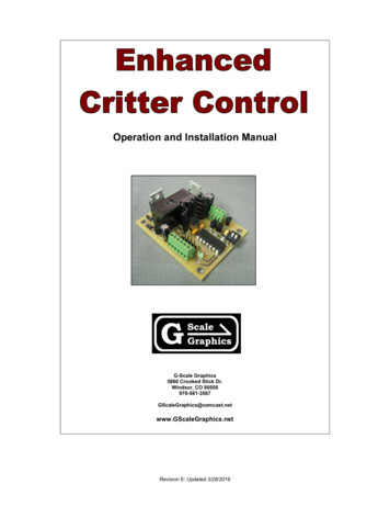
OverviewThe Enhanced Critter Control is a simple way tomanually or automatically control large scale batterypowered “Critters” or large scale locomotives, handson, without the expense and frustration of radio control systems or complex track wiring. Whether yousimply want to run your trains continuously on either aloop or point-to-point layout, do switching in the yards,or have a series of automated station stops, this control system will meet your needs.The Critter Control is also a simple way to control a2nd train on your layout. Speed is readily adjustable,so just set it close to that of your other train, then runat a fixed speed while you control the primary trainusing your power-pack or radio control as needed tokeep them separated.Unlike a simple on/off battery power scheme, the Critter Control smoothly accelerates and decelerates prototypically, which also avoids gear damage.Enhanced Critter Control board, reed switch,and rotary speed switch module with built-inpush button.A powerful micro-controller handles all of the control logic and sends signals to a 5 amp motor driver. The driver islarge enough to handle most locomotives pulling a full train, yet the board is small enough to fit in most “Critters”.Manual Hands-On operation - A roof mounted rotary switch with built-in push-button is the primary control. Pushthe button to start the train. The train will smoothly accelerate to your previously set running speed. Push thebutton again and it will decelerate to a stop. The same button can be used to reverse direction or make emergency stops. Running speed is adjusted by rotating the switch as your train passes by. Since the speed setting is retained in non-volatile memory, you won’t have to do this often. And, it will still be there the next timeyou power up. Acceleration rates are user programmable.Automated operation - Back ‘n forth trolley operation and continuous loop operation with multiple station stopsare built into the Enhanced Critter Control system. Track mounted magnets and a loco mounted reed switchinitiate deceleration to a stop at the station, where it will stay for a user programmable period of time, and thenaccelerate back to running speed (the rate of acceleration is also programmable). A second magnet in thepath during slowdown to the station will initiate direction reversal after the timed stop. Station stops can alsobe programmed for random operation adding interest to your layout.For track dedicated to back ‘n forth trolley operation, with no intermediate station stops, one magnet can beused at each end to decelerate and reverse the trolley. (See Programming options).The Enhanced Critter Control consists of a small circuit board ( 2.4”L X 1.9”W X 1.0”H) and off-board speed control. This gives you the freedom to mount it where ever you want. A rotary switch with built-in push button makesfor a simple one-piece control that can be easily disguised as a smoke stack or vent. The reed switch can bemounted under your loco to implement automated station stops and/or back ‘n forth trolley operation.Note: To complete your battery power conversion, you will also need to provide a power on/off switch,battery pack, battery charger, and battery charging jack (optional). The G-Scale Graphics “Battery Conversion Modules” combine some of these functions and reduce wiring.Directional lighting outputs are provided to power your locomotive’s front and rear lights; LEDs or lamps. No external resistors are required for LEDs.The on-board LED and built-in diagnostics allow you to verify proper wiring connections right on the bench. It alsoprovides a visual indication of proper reed switch operation.Page 2
InstallationTrack Power to Battery Power ConversionAll track powered locomotives are very simple, electrically. Track power is picked up from the rails via pickups andusually connected directly to the motor. Sometimes there are switches in the circuit to reverse polarity or turn offthe motor. These connections need to be modified in order to properly connect the battery powered driver board.Converting to battery power consists of these basic steps.1. Determine battery voltage requirements.Before you disturb any wiring, run your locomotive at the fastest speed you like to run on your layout andmeasure the track voltage. Add at least 2 volts to this measurement to account for low batteries and driverlosses. Round this value up to the nearest 1.2v increment, and you have the number of cells you need.For example: Track voltage measures 11.6V at speed. (11.6 2)/ 1.2 11.3. You will need at least 12 cells.12 X 1.2V 14.4V. (14.4V is a popular value for steam locomotives. Many critters can run on 12V. Dieselsusually require 18V or more).2. Disconnect the track power pickups.By isolating your locomotive from track power, you can run more than one locomotive on the same track atthe same time, either battery powered or track powered. If you don’t do this, your battery will be directly connected to your track power supply, resulting in damage. Note that in doing this, you have also removed powerfrom all lighting circuits, smoke units, and any other accessories that were running from track power. For battery power, smoke units are usually not used due to the high current requirements that will quickly drain thebattery pack. Understanding existing wiring and/or circuit boards without documentation can be difficult. Youmay choose to just remove it all and wire directly to things you can see and understand.3. Find a direct connection to the motor.The output of the controller needs to be connected directly to the motor. All other control boards and switchesmust be removed from the circuit. Depending on the design of the locomotive, this may be an extremely simple process, or it may be difficult. Some motor blocks make it very simple. You will find two pairs of wires. Oneset goes to the track pickups, and the other goes to the motor. You can verify which pair goes to the trackpickups using a continuity checker or ohmmeter. Track pickups will have continuity from one pin to one set ofwheels. The motor will read a small resistance value across the two wires (e.g. 18 ohms). Simply disconnectthe track pickup pair and connect the motor pair to the controller.4. Install all of the components and wire them together(battery pack, power on/off switch, charging jack, controller, and lights)Installing the new components is a packaging exercise. Where will it all fit? Space for the battery pack andcontrol board is usually the biggest consideration. And, where to locate the switches so they are accessible?WiringAlways use stranded wire and tin the ends with solder prior to making any connections. Wiring for the control inputs at terminals 1 thru 10 can be smaller gauge wire (26 Ga.). Wiring for the power input and motor output circuitry on terminals 11 thru 14 needs to be heavier gauge wire (20 or 22 Ga.) Any wiring connections or splices notdirectly connected to a component must be covered. Use heat shrink tubing or wire nuts.SkillsAll connections to the Rotary Critter Control can be made via screw terminals. However, basic wiring and soldering skills are required to make proper connections to the toggle speed switch version, power on/off switch, andcharging jack. Some drilling and minor fabrication or modifications to the unit under conversion may also be required.Tools & MaterialsA low wattage soldering iron, side cutters, needle-nose pliers, wire strippers, a 1/16” or 5/64” slotted screwdriver,resin core solder, 26 and/or 22 Ga. Wire, and heat shrink tubing are recommended to properly complete the wiring. A suitable drill, PCB stand-offs, and double-sided foam tape may be useful for mounting components.Page 3
Installation of the Critter Control BoardThe Critter Control board can be mounted most anywhere, but allow space for access to wiring. No metal shouldbe in contact with the board. The power components (heat sink and large metal tab) will get hot, so keep them outof direct contact with plastic. Mounting holes in the corners of the board may be used along with stand-offs for aprofessional installation, or simply use double-sided foam tape on the bottom side of board to secure the board toa plastic surface. Handle the board by the edges, avoiding direct contact with the circuitry. Static electricity candamage the components. Try to ground yourself by touching something metal prior to handling the board. Refer tothe wiring diagrams at the end of this manual.Power Input (Battery)The Critter Control will not function below 7v input at terminals B , B-.Reverse polarity will not cause damage, but the control will not operate. Voltage in excess of 30V may cause damage. Battery packs of 8to 20 cells are suitable (nominal 9.6 to 24.0V). A 20 cell pack cancharge up to 30.0V. An 8 cell pack can discharge to 8.0V.Charging JackPower On/Off switchWhen making wiring connections to the battery pack, use extreme caution to avoid shorting the leads together. Donot connect the battery to the circuit until all other wiring has been completed. The battery pack should have aquick disconnect connector for safety and ease of replacement.Note: Make sure terminal B is positive ( ) and terminal B- is negative (-). This product is notintended for track power applications where polarity reverses.The power on/off switch can be located on the floor under the loco. If you have a critter, the charging jack can alsobe floor mounted, since you will probably take it off the track for charging. For a full size locomotive and/or tender,you may want to locate the charging jack on the end of the car to enable charging in place on the track. Theswitch in the charging jack isolates the battery from all other electronics when a jack is plugged in, regardless ofthe position of the power on/off switch. Warning! The heat sink on the voltage regulator may be extremelyhot; enough to burn you if touched, or melt any plastic it comes in contact with.Warning ! A 5 amp fuse should be installed in-line with the positive battery lead to protectagainst accidental short circuits, which may damage the control, and melt wiring and/or plastic.Motor OutputConnect terminals M and M- directly to the motor. All other unknown circuitry must be disconnected from themotor. A maximum of 5 amps continuous current is available from the board. Warning! At 5 amps the powertransistor on the board (metal tab) will be extremely hot. Enough to burn you if touched, or melt any plastic it contacts.At power-up the motor output will provide a voltage to the motor that is positive on terminal M , negative on M-.This is intended to be the forward direction of the locomotive. It will work either way. But with this polarity theboard will draw considerably less current in the forward direction, thus reducing heat, and extending battery life,assuming you do most of your running in the forward direction. For automated back and forth operation, it willmake no difference.Directional LED OutputsConnect directly to the LEDs; terminal 8 to the anodes( ), and terminals 9 and 10 to the cathodes(-) of the forward and reverse LEDs respectively. No current limiting resistors are required.To provide constant current to one or more LEDs, regardless of direction, jumper terminal 9 to10, and connect the LED anode( ) to terminal 8, and the cathode(-) to either terminal 9 or 10.Control InputsThe controls should be mounted where they can be easily reached as thecritter or train passes by, usually roof mounted. The rotary switch is designed to accept a radio knob using a set screw. A false smoke stack orvent can be fabricated to act as the knob. The shaft can also be shortened. Wiring connections are made via screw terminals.Rotary Switch (& dime)LEDPage 4
A reed switch is only required for automated operation. It must be installed within 1/4” oftrack magnets, in either a horizontal or vertical orientation. You can usually mount it on theunderside of a truck in the horizontal position parallel with the track. Silicone adhesiveworks well. Or, it can be vertically mounted through a 1/4” diameter hole in the floor of thevehicle. Do not mount the reed switch below the level of rail tops, as it will hit the rails inturnouts.Reed SwitchTestingThe on-board green LED can be used to check out your wiring and most of the board functions. This should be allyou need to get going, but if you are still having problems and you have a volt-ohm meter you can also take themeasurements indicated below.Power-up (LED ON)When power is first applied to the board, the LED should be ON steady. This tells you the power input polarityis correct and the Critter Control’s 5V power supply is working. Measure 5.0 - 0.5 VDC at terminal 1 , 5-. Ifthere is a problem, check the voltage and polarity at terminals B , B-. It should measure between 7.0 and 30.0 VDC.Speed Setting Switch (LED flashes OFF)Rotate (or toggle) the switch in either direction. The LED should flash rapidly. You could also measure thevoltage at terminal 2 , 5-, and terminal 3 , 5-. The voltage should momentarily drop from 5V to 0V. If notcheck the wiring of the speed switch.Reed Switch (LED OFF when activated)While in the stopped mode, anytime a magnet is passed within range of the reed switch, the LED will turnOFF until the magnet is removed or out of range. This is very handy to check your reed switch and magnetalignment. Slide the loco back and forth over the magnet, while watching the LED. Your magnet height shouldbe just under the top of the rail. The reed switch should be just above the top of the rail. There should be lessthan 1/4” spacing between the magnet and the reed switch. Measure the voltage at terminal 6 , 5-. The voltage should momentarily drop from 5V to 0V. If not, check the reed switch wiring.Push-Button (LED flashes, then OFF)When you press the button, the LED will flash a couple of times, then turn OFF. This indicates the buttonworked and you are now in the run mode. The motor should accel to the set running speed. CW rotation increases speed. CCW decreases speed. Pressing again should decel the motor to a full stop and turn on theLED. If the LED won’t flash when the control button is pressed, check the rotary switch/control button wiring.Measure the voltage at terminal 4 , 5-. The voltage should drop from 5V to 0V when the button is pressed. Ifthe motor doesn’t run after increasing the speed setting, check the motor wiring. Voltage at terminals M , Mshould increase with increasing speed, to a maximum of your battery voltage. If the loco runs backwards, reverse the wiring at terminals M and M-.Changing DirectionAt power-up, direction is set to “forward”, and the forward light should be ON (if connected) and the reverselight OFF (if connected). While stopped, a quick momentary button press, followed by a longer press will startthe loco in the opposite direction. You may hear the relay click. The reverse light should now be ON, and theforward light OFF when running in reverse.Page 5
Manual OperationPower-UpWhen you first power-up your Critter Control it will be in the “Fully Stopped” mode and the on-board diagnosticLED can be used to check wiring connections, as previously described.Auto / Manual OperationBy default, the control powers up with automated station stops enabled. However, there may be times you don’twant to make the station stops. You can disable auto mode without removing your track magnets. Just hold downthe control button for about 1 second while turning on the power. To go back to auto mode, cycle power off, thenback on (control button not used). Note: If you hold the button down for 5 seconds or more, you will enter the motor starting voltage mode.Starting and StoppingPress the control button to start. The locomotive will accelerate to running speed. Press it again, and it will decelerate to a stop. Press and hold the button anytime for an emergency stop. During a timed station stop initiated bya track magnet, a button press will halt the timer and the locomotive will remain stopped.Speed ChangesChanges to running speed can only be made while actually running at speed. Controls will have no effectduring stops or while accelerating or decelerating. Roof mounted controls make it easy to adjust speed as the locomotive passes by.Rotary Switch There are no physical stops but you can feel detent positions as it is turned. CW rotation increases speed, CCWrotation decreases speed.Memory The current speed setting is always retained in non-volatile memory. So, the next time you power-up and pressthe button, you will return to the same speed you were running during your last operating session. The speed setting is saved every time you initiate a stop.Changing DirectionWhile fully stopped, a quick momentary button press ( 1/2 sec) followed by a longer press (about 1 sec) and release will cause the locomotive to change direction.Set-UpMotor Starting VoltageWhen you press the control button to start your loco, the voltage starts ramping up from 0 volts. However, yourmotor will require something greater than 0 volts to start moving, perhaps 1 or 2 volts. The result may be a considerable delay between the time you press the button and motion of your locomotive. This can be adjusted, but try itat the factory setting of 0 volts first. Then if you need to change it, here’s how .1. Prior to turning on the battery power, hold down the control button.2. Turn on the battery power and continue to hold the control button for at least 5 seconds. After 5 sec, the onboard diagnostic LED and the forward light output (if you are using it) will flash 5 times. You are now in themotor starting voltage calibration mode. (Both the forward and Reverse lighting outputs will be on during thistime.)3. Increase the speed setting until the motor just starts moving, then decrease it slightly.4. Press the control button. The on-board LED will flash 5 times, indicating your new motor starting voltage hasbeen saved and you are now back in the stopped mode, and can resume normal manual operation.5. Experiment with starting and stopping the loco. If there is still a significant delay, you may need to raise thestarting voltage a bit. If the loco jumps when starting, instead of smoothly accelerating, you may have thestarting voltage set too high.6. If you power down and go back into the motor starting voltage mode again, the motor voltage will return to thelast setting you made. You can now raise or lower it from that point.Note: Upon exiting the motor starting voltage mode, automation will be disabled. To restore auto operation, cyclebattery power off and back on.Page 6
Trouble ShootingManual Operation Nothing seems to be working Check the power. The on-board LED should be ON when you first power-up.You should measure between 7 and 25 volts DC applied to terminals B , B-.You should measure 5 volts DC on terminals 1( ), 5(-)Verify all wiring connections. Pressing the button, but it won’t go Press and hold the control button for a couple of seconds to insure you are in the “Fully Stopped” mode.Then momentarily press the control button. If it doesn’t go, increase the speed setting.(Also try decreasing the speed setting, in case it is wired backwards.)If it still doesn’t accelerate, remove power and try again. When I first power up and accelerate to speed, the loco runs in reverse .Reverse the wires at the motor output, terminals M .M-.It is preferable to run in the forward direction after power-up to conserve battery life. The loco won’t run as fast as I like even though I keep trying to increase the speed setting Maximum speed is determined by your battery voltage. You need more cells/voltage. The speed setting control is working backwards Reverse the wiring at terminals 2 & 3. Can’t change the speed .The speed setting switch will only work while running at speed. Speed cannot be changed while stopped,accelerating, or decelerating. The speed setting seems to be changing on me.The “Speed Setting” is actually a “% of battery voltage setting”. Hence, as the battery voltage decreasesduring discharge, the speed will slow down some. Also, changes in load, such as adding more rollingstock to the train, will decrease speed slightly. Loco starts moving as soon as I turn on the power The motor starting voltage is set too highPage 7
Automated OperationAn automated station stop slows down the train, waits at the station between 15 and 60 seconds, depending onthe programmed value, then accelerates back to running speed. Station stops add interest to your open house orpublic displays.Automated operation is easily achieved with the Enhanced Critter Control. You just need to add a reed switch toyour locomotive and place some track magnets on your layout.Automated station stops are initiated by a track magnet placed ahead of the station. The magnet initiates deceleration to a stop. You can make as many stops as you like, one magnet per station. When running in both directions, two magnets per station are required, one for each direction. Place the magnets such that the loco stops atthe same location when running from either direction. The magnet in front of the locomotive when leaving the station will be ignored.The distance the magnet is located from the station will depend on your running speed. Some trial and error willbe required to find the proper location. First, establish your running speed. Since your running speed is maintained in memory, the distance will never change unless you vary the running speed.Avoid the repetition of a station stop every time a magnet is encountered by programming random station stops.You can control the percentage of time the train will stop after crossing the magnet. This adds an incredibleamount interest to your layout for both you and your visitors.For tracks with intermediate station stops, automated reversing is accomplished using a second magnet placedabout 5” to 8” after the decel magnet. This second trigger will cause the loco to depart the station in the oppositedirection. Magnet spacing requirements vary with speed of the loco. 6” or greater is a good starting point. As longas the second magnet is crossed prior to coming to a full stop, it should work. Caution: You should provide for endof track bumpers or wheels chocks, just in case.For track dedicated to back ‘n forth trolley operation, you can use just one magnet on each end to start deceleration and automatic reversal. (See Programmins options.)Any magnet of suitable size and strength can be used. But they must be located no more than 1/4” from the reedswitch passing overhead. Track magnets mounted higher than the rail tops will be susceptible to damage by trackcleaners and snow plows.But I already use magnets to trigger my sound system!Page 8
You may have existing track magnets used to trigger the bell and whistle of your sound system. For example;whistle magnet on the right, bell on the left. Both systems can share the same magnets fairly easily. Install yourCritter Control reed switch on the same side you use to trigger the bell. The bell will ring as you approach the station, and the whistle will still blow in your favorite locations. If your sound board uses the negative battery terminalfor common, you can also share the same reed switch. One side to common, the other side to both the soundboard and the Critter Control.Movable MagnetsBeing able to easily move your magnets to new track locations makes it much easier to set up your station stops,or change things as the need arises. If you just place a loose magnet in between ties, the metal of the loco maypick it up as it passes.G-Scale Graphics Track Magnets are designed for two reed switches placed 1.0” apart. They are easy to insertbetween track ties, and easy to move. They can also be rotated for use as a “left’ or “right” side magnet.The two magnets for reversing should be placed at least 5” apart for slow moving locos, at least 8” apart for fastmoving locos.Trouble Shooting Automated Operation Loco fails to stop after crossing a single decel magnet. Verify proper installation of reed switch and magnet.If the loco fails to reverse after crossing two magnets, the magnets are too close together and/or the locospeed is too fast. Random station stops must be set for 100%.(Hence the need to protect the end of point-topoint track with a bumper or derail).The loco will also fail to reverse if the magnets are too far apart and/or the loco is running too slow. It willcross the first magnet, but stop prior to the second, and treat it as a station stop.If you can’t get the loco to make a proper intermediate station stop in both directions after making the aboveadjustments, it may be due to excessive grade of the track. Intermediate station stops work best with a flatapproach from both directions but should tolerate 3% grades.The location of the station stop changes over time. Magnet locations are only precise for one given speedsetting. As the battery discharges, the loco will slow somewhat, even though the speed setting has not beenchanged. This effects the stopping distance after a magnet trigger.Page 9
Programming Procedure for Enhanced Critter ControlUser configurable parameterscan be programmed using the2-position DIP switch,on-board push-button switch,and on-board LED.Enter Programming ModeWith power on, momentarilypress the yellow push-buttonlocated next to the DIP switch.The LED will begin flashing.Select ParameterSelect the parameter you wishto view or program using theDIP switch. (the white squareindicates position of the switch;e.g. for parameter 0, allswitches are in the down or offposition.View Current Option CodeThe LED will flash the optioncode for the currently selectedparameter; e.g. two flashesfollowed by a pause indicateoption 2.Change the Option CodeMomentarily press the pushbutton during the pause to advance the option to the nexthigher number, until you getthe desired number of flashes.Save the Option CodePress and hold down the pushbutton for about 4 secs untilthe LED starts flashing rapidly,which indicates the save iscomplete.Option15 secs210 secs [factory setting]320 secs430 secsDIP SwitchOptionUpon return to power, the newoptions will be activated.Parameter 1 - Station Stop Accel/Decel Time1Fastest2Faster3[factory setting]4Slower5SlowestOption1Parameter 2 - Station Stops from Reed Switch100% / Trolley mode. [factory setting]Reed Switch always triggers a station stop.TWO magnets to reverse.275%, Reed Switch triggers station stop 75% ofthe time350%, Reed Switch triggers station stop 50% ofthe time425%, Reed Switch triggers station stop 25% ofthe time50%, Reed Switch triggers station stops 0% ofthe time6Select the next ParameterRepeat the above as neededto view or make changes toother parameters.Exit Programming ModeTurn off power.Parameter 0 - Station Stop Dwell TimeOption100% Trolley mode. ONE magnet reverses.Reed Switch always triggers a station stop andthen reverses.Parameter 3 - Button Press Accel/Decel Time1Fastest2Faster3[factory setting]4Slower5SlowestPage 10
Enhanced Critter Control SpecificationsBoard Revision “D”MechanicalPhysical Size: PCB – 2.4” X 1.9”, Max component height – 1.0”. Weight: 1.3oz.User Connections: Screw clamp terminal strips accept individual wires, 30 to 20 AWG.Requires a 1/16” or 5/64” slotted screwdriverElectricalPower Input from battery pack (Terminals B ,B-)7.0V min to 25.0V max8-20 cell battery packsNominal 9.6V to 24.0V battery packs (1.2V per cell)8 cells can discharge to 8.0V (1.0V per cell)20 cells can charge to 30.0V (1.5V per cell)Reverse polarity protectionPower Consumption (due to board, no motor load)Forward motor direction: 50 ma (30V supply)Reverse motor direction: 150 ma (Relay energized, 30V supply))Motor Output (Terminals M ,M-)5 amps max, continuousPWM (Pulse Width Modulated)Polarity reversal via relay contactsMax amplitude: Battery voltage minus driver lossTypical voltage loss across driver: 0.1V @14.4V, 1A: 0.3V @24.0V, 2.5A.Control OutputsLED/Lamp Drivers: Max load 500 maLED current source: Terminal 8 20 maLamp voltage source: Terminal 7 battery voltage at power inputForward Lamp/LED-(open collector) Terminal 9Reverse Lamp/LED-(open collector) Terminal 10Control InputsControl Switch Input (Terminal 4)Momentary push-button switch (NO), contacts normally open, built into rotary speed switchSpeed Setting Inputs (Terminals 2,3)Rotary Encoder switch; quadrature output, 24 pulses per revolutionapproximately 2 full turns min to max speed(drill 9/32” hole)Reed Switch (Terminal 6)(drill 1/4” hole)SPST - Normally Open, installed within 1/4” of track magnet, vertical or horizontal orientationTrack MagnetsMust be placed on roadbed within 1/4” of reed switch.Spacing for pair of reversing magnets: 6” nominal. No more than distance required to decel to a full stop.Minimum track length for auto reverse operation: Depends on speed; about 7 feet.Battery Power Accessories (available from G-Scale Graphics)Battery Conversion Module; (built-in Power on/off Sw, Charging Jack, 5A fuse, power distribution)Power On/Off Switch: Sub-Miniature w/short handle, SPDT (On-On), 3A, 28 VDC(drill 3/16” hole)Charging Jack: 2.5mm, 5A, w/switch(drill 5/16” hole)Page 11
Enhanced Critter ControlWith Rotary Speed SwitchWiring DiagramReed SwitchPage 12
The Enhanced Critter Control consists of a small circuit board ( 2.4"L X 1.9"W X 1.0"H) and off-board speed con-trol. This gives you the freedom to mount it where ever you want. A rotary switch with built-in push button makes for a simple one-piece control that can be easily disguised as a smoke stack or vent. The reed switch can be