Transcription
Installation, Operation and ServiceManualBluezone Model 2400Air Cleaning SystemEvo America, LLC 20360 SW Avery Court, Tualatin, OR 97062www.Bluezone.com support@evoamerica.com 503-626-1802
Document #: BPI-PM002-01Do not operate the Bluezone Model 2400while fogging with chlorine bleach or otherdisinfectant solutions. Disinfectants canpoison the Bluezone catalyst and reduce itseffectiveness.IMPORTANT SAFEGUARDSREAD AND SAVE THESE INSTRUCTIONSSafetyThis operation and service manual containsimportant instructions and safety informationabout the Bluezone Air Purification System.Observe the following dangers, warnings,cautions and notices when installing,operating and servicing the Bluezone Model2400. Turn off the Bluezone Units ifdisinfectant fogging or cleaning isunderway.Turn Bluezone units back on afterdisinfectants have dissipated.Never hose down the Bluezone Model 2400or clean with a water jet. Direct flow of wateronto the catalyst can reduce its effectivenessin eliminating ozone.Electrical SystemEnergized electrical circuits present apotentially life-threatening hazard.Turn off Bluezone units and cover with plasticif the room is being hosed with water orsteam.Ensure the unit’s power cord is unpluggedbefore performing any installation or servicework.Ensure there are no other electrical powercircuits connected to the Bluezone Model2400.Do Not Operate unit with a damaged cord orplug. Discard unit or return to an authorizedservice facility for repair.System MaintenanceFollow all lockout/tagout procedures for allelectrical circuits.The Bluezone Model 2400 contains 4 UV-Clight bulbs; the UV light is completelycontained inside the unit during operation.Unplug or disconnect the unit from powersource prior to any servicing.System OperationThe Bluezone Model 2400 has multiple safetysystems to ensure that you cannot view theUV bulbs while they are operating.Do NOT attempt to override the cover switchto allow the bulbs to operate when the coveris off.1
Document #: BPI-PM002-01ensures safe operation at all times and alertsthe user to any system faults.Skin or eye damage may result from directlyviewing the light produced by the lamp in thisapparatus. Always disconnect power beforerelamping or servicing. Replace lamps usingLamp Replacement Kit Model No. 005000002, manufactured by Bluezone ProductsInc. or an Authorized Bluezone Partner.SpecificationsThe specifications of the Bluezone Model2400 are shown in Table 1.Table 1: Bluezone Model 2400SpecificationsNever look at an illuminated UV-C bulbwithout proper eye protection against UV lightfrequencies.Specification CategorySizeThe UV-C lamps generate ozone. This ozoneis contained inside the Bluezone Model 2400.Model 240031” X 14” X 13.5”79cm X 36 cm X 34 cmProduct WeightWhen conducting maintenance, powerdown the unit and wait 15 minutes beforeremoving the cover. There will be residualozone inside the Bluezone Model 2400. Donot breathe air directly from inside the unit.Shipping Size25 lbs./11kg36” X 20” X 20”91cm X 51cm X 51cmDescriptionShipping Weight28 lbs/13 kgOperating Environment50 F – 104 F1C – 40CThe Bluezone Model 2400 is an airpurification device that eliminates airbornecontaminants including microbes (virus, fungi,mold and bacteria), odors and ethylene.up to 85% RHStorage Environment-4 F – 150 F-20C – 65Cup to 85% RHThe Model 2400 can be hung or mounted tothe ceiling or wall, or located on a shelf.Input VoltageThe Bluezone Model 2400 draws in aircontaining viruses, mold, spores or fungus,and discharges air with a highly reducedconcentration of these impurities.CurrentPowerThe unit is completely self-contained. Thefacility, equipment, and personnel have nocontact with the process that is cleaning theair.The Bluezone unit’s operation is controlled bya microprocessor-based controller that2120 VAC 1 Phase3 amps (at 120VAC)250 Watts maxElectrical ConnectionIEC 320-C13 120 VAC power cordMounting Options:Hung from ceiling, placed onshelf/rack/cart, or mounted to wallCertificationscETLus ListedARB certified – Ozone EmissionsNSF per request
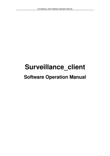
Document #: BPI-PM002-01Key Components524136Figure 1: Bluezone Key Components3
Document #: BPI-PM002-01Electrical SystemUse the first two numbers in the serial number to identify the wiring in your unit.First two numbers of serial numberWiring diagram45Figure 349Figure 4Figure 2: Location of Serial Number4
Document #: BPI-PM002-01Wiring diagrams of the Model 2400-045 and the 2400-049 are shown as Figure 3 and Figure 4respectively.Figure 3: Wiring Diagram of Model 2400-045 Unit5
Document #: BPI-PM002-01Figure 4: Wiring Diagram of Model 2400-049 Unit6
Document #: BPI-PM002-011.InstallationAn overview of Mechanical and ElectricalInstallation instructions is contained in thissection. Details of steps to hang the Model2400 from the ceiling or mount on a shelfare contained in Appendix A.2.3.Installation GuidelinesPlace the Model 2400 in the room so that airflow from the HVAC system, fans or otherair flow systems does not blow directly intoor pull air through the Model 2400 air inlet orclean air outlet.4.Ensure a minimum clearance distance of10’ (3m) from an air handler outlet to theModel 2400 to avoid excessive air flowthrough the unit.Place the unit so that the control panel anddisplay are visible and accessible.If multiple Bluezone Model 2400 units arebeing installed in a room, the following arerecommended guidelines for the placementof the Bluezone units:7Distribute the units relatively evenlythroughout the space.Generally spreading the locationsacross the available space is goodpractice.Warning: Hang the units from theceiling, mount to the wall or on ashelf/rack to avoid unintended bumpingof the units.Units hung from the ceiling should behung to the level of the lights, but notbelow lights to avoid blocking light tothe plants.5.Warning: If the unit is located in anarea with foot traffic and there is aconcern that it could be bumped bypersonnel, it should be labeled withcolored tape to make it more visibleand reduce the risk of collision.6.Warning: Locate the junctionboxes for the units as close as possibleto the units to avoid the risk of hookingthe cord and pulling it out. If thedistance to the junction box is morethan 2’ (0.6 m), the cord should be tiedto the wall, rack, or ceiling to keep itprotected.
Document #: BPI-PM002-01Mechanical InstallationSee Figure 6 for mounting kits.The Bluezone unit can be hung from theceiling or placed on a shelf. A ceiling mountkit and a shelf mounting kit are available forpurchase.Sound deadening mufflers can be installedto reduce noise in occupied spaceapplications. Installation instructions for themufflers are included in Appendix A.A drawing of the mounting locations on theModel 2400 is provided in Figure 5.Figure 5: Bluezone Model 2400 Mount Dimensions (units in inches)8
Document #: BPI-PM002-01Figure 6: Illustration of the Ceiling Mount and Shelf Mount9
Document #: BPI-PM002-01Electrical InstallationThe Bluezone unit is equipped with a powerentry module.WarningThe power cord is attached to the front ofthe unit and may be caught and pulledduring activities in the space. Secure thepower cord to the shelving, wall or otherstable surface.Model 2400-049 must be connected to120VAC 60Hz input onlyModel 2400-045 is may be connected to120V or 230V AC 50/60Hz input.The unit is cETLus listed at 120 VAC.Electrical RequirementsInput Voltage: 120VACInput Frequency: 60HzThe Model 2400 is shipped standard with a6’ (2m) power cord.Input Current: 3A max @ 120VACPlug the power cord into the power entrymodule.Input Power: 250W maxOnce the Model 2400 is positionedmechanically in the space, plug the cordinto the nearest un-switched electrical outletrated to the voltage on the unit’smodel/serial number plate.Secure the cord.10
Document #: BPI-PM002-01OperationPower SwitchCircuit BreakerPower EntryModule(AC Inlet)Bulb CounterReset ButtonFigure 7: Control Panel on Bluezone UnitOnce the Model 2400 is mounted and wired, it can be turned ‘On’ using the power switch on thecontrol panel.Toggle the power switch to the “On” position to energize the unit.Normal OperationOnce the Bluezone is switched “On”, the Display Screen will indicate “Bluezone” on a greenbackground on the top line.The bottom line of the display screen will confirm bulb operation, a bulb life counter, thetemperature, humidity and fan speed.11
Document #: BPI-PM002-01Figure 8: Display Sequence in Time12
Document #: BPI-PM002-01Fault Conditions and Fault CodesIf there are issues with the operation of the Model 2400, the onboard diagnostics will indicatethe nature of the problem.Display Screen codes are shown in Table 2.Table 2: Display Screen Status Indicator Fault CodesDisplay ColorGreenBackgroundFlashing GreenBackgroundDisplay TextBluezoneUnit conditionsscrollingBluezoneUnit conditionsscrollingFaultOperationAction to TakeSystem operatingproperly.OperatesNoneUnit is off and willpower up whentemperatureincreases to 0C orhumidity dropsbelow 85%Do not run unit in afreezingenvironment.Unit automaticallypowered down.Check fan for anyvisible obstructions.Contact BluezoneProducts forservice.Freezingtemperaturesdetected, orHumidity abovethresholdFan not rotating, orYellowBackgroundContactBluezoneHumidity sensorfailure, orBulb counter failureReplace Bulbs,Unit conditionsscrollingBulb life 7,200hours of operation.Operates until8,800 hours ofoperation.Check bulb counterOrder new bulbsContactBluezoneOzone sensor TripUnit automaticallypowered down untilsensor resets.Contact BluezoneProductsBulb life at 8,800operation hours.Unit automaticallypowered down untilbulbs replaced andcounter reset.Replace bulbs andreset bulb lifecounter.Red BackgroundReplace Bulbs13
Document #: BPI-PM002-01Diagnostics3.Restart the unit.a. Power “Off” unit by pressingthe power switch located onthe control panel.b. Wait 5 seconds.c. Turn unit “On.”d. Repeat 3 times4.Check whether the unit’s circuitbreaker has tripped.a. Visually check the circuitbreaker located on thecontrol panel. If a white stripis visible, then the breakerneeds to be reset.b. Power “Off” unit using thepower switch located on thecontrol panel.c. Reset circuit breaker locatedon the control panel bypushing the visible indicatorback into the circuit breaker.d. Turn unit “On” using thepower switch located on thecontrol panel.If the Display Screen has no light or textthen the Model 2400 is not beingpowered. Check the following list forpossible causes and solutions:1. Make sure the cover is on andthe Cover Switch is Activated.Controls will not energize if the cover isoff or if the cover switch is not engaged.Make sure the cover switch tab engagesinside the cover switch opening.See Figure 9 for proper installation ofthe cover switch.2. Check that unit is powered.a. Power “Off” unit by pressingthe power switch located onthe control panel.b. Plug unit in.c. Turn unit “On.”DangerDO NOT activate the cover switch without the cover on. UV light will be emitted. 14
Document #: BPI-PM002-01Cover switchCover switch holeFigure 9: Bluezone Cover Switch and Cover Switch Hole15
Document #: BPI-PM002-01New Equipment WarrantyAll Bluezone products have been tested byindependent labs and in many facilities,proving the performance as described in ourliterature. Our air purification equipment is apowerful tool to help purify yourenvironment yet, we cannot guaranty thatunder your operating conditions andprocedures, the results will be the same asexperienced by other users.Online warranty registration form must becompleted to validate your New EquipmentWarranty. Please visitwww.BluezoneFresh.com to complete theonline warranty registration.Bluezone Products, Inc. warrants that newequipment manufactured in Bluezone’sfacilities are free of defects due to poormaterials or workmanship for a period of 1year from the date of purchase.If you are not satisfied with the purchase orthe operation of our equipment, it can bereturned if the equipment was un-used andwas returned within 14 days. The customerwill be charged return freight and anadditional 10% of the purchase price asa restocking fee.Bluezone Products, Inc. warrants that theequipment will function properly, to ourspecifications and will be repaired, ifnecessary, at no charge for a period of 1year (See our warranty policy for details).Bulb DisposalBulbs contain a small amount of mercuryBulb handling should be similar to that used for fluorescent or compact fluorescent bulbs.Bluezone Products, Inc. recommends that you take advantage of available local recyclingoptions for CFLs. Lists of recycling facilities are available at: www.earth911.org.Dispose of according to local, state or federal laws.16
Document #: BPI-PM002-01ServiceBULBS NEED TO BE REPLACED AFTER 8,800 HOURS OF USE. BULB KITS MUST BEPURCHASED DIRECTLY FROM BLUEZONE PRODUCTS OR AN AUTHORIZED PARTNERAS THEY ARE PROPRIETARY BULBS.Please call 503-626-1802 or emailsales@evoamerica.com for orderinginformation.Bulbs must be replaced at 8,800 hours ofoperation. The display screen readsaccumulated bulb hours throughout theunit’s operation. At 7,200 hours the displayscreen will turn yellow and read “ReplaceBulbs.” The bulbs should be ordered andreplaced immediately. At 8,800 hours, thedisplay screen will turn red and the unit willautomatically be powered OFF until bulbsare replaced.IMPORTANT: Each bulb kit satisfiesreplacement parts for 1 unit. The four bulbsin each replacement kit cannot be replacedwith bulbs purchased from anywhere, butBluezone Products or an AuthorizedPartner. Installation of the incorrect bulbsresults in a voided warranty. Purchase ofbulbs from an outside vendor results in avoided warranty. Bluezone will not operatecorrectly with bulbs purchased from outsidevendors.After bulbs are replaced, the bulb counterneeds to be reset. To reset the bulb counterplease follow the steps below.1) Press and hold the red bulb counterreset button for 5 seconds. Thedisplay screen will read “Hold: resetcounter” during the 5 second hold.2) After holding for 5 seconds, thedisplay screen will read “push toconfirm.” Release button and pushto confirm reset.Service Kit includes: (4) U-shaped bulbs(2) Nitrile glovesExta cover screwsAdditional tools needed: A bulb replacement kit and instructions canbe ordered from Evo America.17N/A
Document #: BPI-PM002-0112)Instructions for Bulb Replacement:1)2)3)4)5)6)7)8)9)10)11)Toggle the power switch located onthe unit’s control panel to OFF.13)Wait 15 minutes for the ozone toclear from the Bluezone reactionzone.14)WARNING: Before proceedingto next step, unplug the unit from it’spower supply.Use the ¼” hex nut driver to unscrewthe 14 screws on the cover, seeFigure 10 below.Slowly, remove the cover and place iton a flat surface.Use the gloves provided to removeand replace the bulbs. This willprevent oil on your hand fromdamaging the new bulbs.Unscrew the ¼” screws on BulbSupport Wires. See Figure 11 below.Carefully remove Bulb Support Wiresand place aside. See Figure 12below.Unscrew ¼” screws on Bulb Clips.See Figure 13 below.Remove the old bulbs (Note: pull onthem at the ceramic base, not on theglass) Put the bulbs to the side fordisposal.Carefully remove Bulb Clips andplace aside. See Figure 14 below.15)16)Hold replacement bulbs by theceramic end and push the pins intothe slots in the receptacle. They need to be pushed inuntil a “click” is heard andfelt.Put Bulb Clips over new bulbs anduse screws to tighten Bulb Clips inplace.Thread Bulb Support Wires throughbulbs and use screws to tighten BulbSupport Wires in place.Tighten cover back onto the unit.Dispose of used bulbs, according tostandard practice for florescent bulbs.IMPORTANT17) Press and hold the red bulb counterreset button for 5 seconds. The displayscreen will read “Hold: reset counter”during the 5 second hold. See Figure12.18) After holding for 5 seconds, release andpress the bulb counter reset buttonagain to finalize reset. The displayscreen will read “push to confirm” afterthe 5 second hold.Estimated total bulb replacement time:approximately 30 minutes per unit.18
Document #: BPI-PM002-01Figure 10: Unscrew 14 Screws on Bluezone CoverBulb Support Wires to beremoved¼” screws to be removedFigure 11: Remove ¼” Screws Holding Bulb Support Wires19
Document #: BPI-PM002-01Figure 12: Remove Bulb Support Wires and Place Aside¼” screws to removeFigure 13: Remove ¼” Screws on Bulb Support Clips20
Document #: BPI-PM002-01Figure 14: Carefully Slide off Bulb Clips using Nitrile Gloves21
Document #: BPI-PM002-01Figure 15: Completed Bulb AssemblyFigure 16: Bulb Counter Reset Button22
Document #: BPI-PM002-01Appendix A:Bluezone Unistrut Channel Mount InstallationBluezone Shelf Mount InstallationMuffler Installation23
Document #: BPI-PM002-01Bluezone Unistrut Channel Mount InstallationThe Bluezone Model 2400 can be mounted to the ceiling using existing your facility’s existingUnistrut metal framing system, and the Bluezone Mounting Kit as shown below.EXISTING UNISTRUT INFACILITYMOUNTING KITBLUEZONE UNITFigure 17: Drawing of Unistrut Installation24
Document #: BPI-PM002-01Mounting KitFigure 18: Drawing of Mounting KitMounting Kit MaterialsItemNumberNumberof Pieces11Steel mounting plate, 12 AWG, 18” x 18” with rivet nuts installed24Threaded rod ½” – 2-foot standard size, custom lengths available32Strut channel nut with spring, ½”46Washer, ½”52Hex head screw, ½”66Split lock washer, ½”78Hex nuts, ½”DescriptionNot included in kit. Unistrut channelBluezone unit25
Document #: BPI-PM002-01Instructions1. Insert 2 channel nuts 12” apart in Unistrut channel. Please note Unistrut channel isexisting in client facility.Figure 19: Placement of Channel Nuts in Unistrut Channel2. Attach mounting plate to Unistrut channel by inserting hex screws with washer andlock washer into channel nuts.1Figure 20: Attaching Mounting Plate to Unistrut Channel26
Document #: BPI-PM002-013. Insert (4) threaded rods into rivet nuts. Threaded rods should hang Bluezone at thelevel of the grow lights. Ensure all threaded rods are completely inserted.CustomlengthsavailableFigure 21: Placement of Threaded Rods27
Document #: BPI-PM002-014. Attach ½” hex nuts onto all threaded rods, 1” up threaded rod.Figure 22: Attach Hex Nuts on Threaded Rods5. Secure Bluezone to threaded rods using lock washer, washer and hex nut. This steprequires two workers one to hold the Bluezone and one to attach hardware.Figure 23: Securing Bluezone to Threaded Rods28
Document #: BPI-PM002-01Figure 24: Completed Assembly29
Document #: BPI-PM002-01Shelf MountFigure 25: Drawing of Shelf MountMaterialsIncluded in kit: Wall mount shelfMounting bracketsInstallation screws and anchors30
Document #: BPI-PM002-01Figure 26: Shelf Mount Dimensions31
Document #: BPI-PM002-01Muffler InstallMaterials needed: Bluezone muffler1/4” hex nut driverInstructions1. Remove top 2 screws on the fan cover.Figure 27: Bluezone with Fan CoverFigure 28: Screws Removed32
Document #: BPI-PM002-012. Install Bluezone muffler onto the outlet end of the Bluezone. Holes on the top of themuffler clip onto the top 2 rivets of the Bluezone outlet.Figure 29: Bluezone Outlet without MufflerFigure 30: Bluezone Outlet with Muffler33
Document #: BPI-PM002-013. Reinstall screws into muffler and fan cover.Figure 31: Screws not installed into BluezoneMuffler and Fan Cover34
Document #: BPI-PM002-01Figure 32: Screws Installed into Bluezone Muffler andFan Cover35
Document #: BPI-PM002-01Figure 33: Completely Installed Bluezone Muffler36
Document #: BPI-PM002-01Technical Support is provided by:Evo America, LLCA Middleby CompanyOur Ventless and Air Purification Experts20360 SW Avery CourtTualatin, OR 97062USA503-626-1802866-626-1802 Toll-Freesupport@evoamerica.com37
www.Bluezone.com support@evoamerica.com 503-626-1802 . Bluezone Model 2400 . Air Cleaning System . Installation, Operation and Service Manual . Document #: B PI-PM002-01 . 1 . IMPORTANT SAFEGUARDS READ AND SAVE THESE INSTRUCTIONS Safety This operation and service manual contains