Transcription
MPLS Application,Services & BestPractices for DeploymentMonique Morrow (mmorrow@cisco.com)Martin Winter (mwinter@cisco.com)Manila, 26th February 2009 2008 Cisco Systems, Inc. All rights reserved.1
House Rules Please put your mobile phones into silent mode. Kindly do not take calls inside of this room whilethe session is going on. Your feedback on the session is extremelyimportant! We assume that you will be awake and keep usawake as well 2007 Cisco Systems, Inc. All rights reserved.2
Session Agenda MPLS Layer 3 VPN MPLS Traffic Engineering MPLS Layer 2 VPN Q&A 2007 Cisco Systems, Inc. All rights reserved.3
MPLS Layer 3 VPN 2007 Cisco Systems, Inc. All rights reserved.4
Agenda MPLS VPN Explained MPLS VPN Services Best Practices Conclusion 2007 Cisco Systems, Inc. All rights reserved.5
Prerequisites Must understand basic IP routing, especially BGP Must understand MPLS basics (push, pop, swap, labelstacking) 2007 Cisco Systems, Inc. All rights reserved.6
Terminology LSR: Label switch router LSP: Label switched pathThe chain of labels that are swapped at each hop to get from one LSR to another VRF: VPN routing and forwardingMechanism in Cisco IOS used to build per interface RIB and FIB MP BGP: Multiprotocol BGPPE: Provider edge router interfaces with CE routersP: Provider (core) router, without knowledge of VPNVPNv4: Address family used in BGP to carry MPLS VPN routesRD: Route distinguisherDistinguish same network/mask prefix in different VRFs RT: Route targetExtended community attribute used to control import and export policies ofVPN routes LFIB: Label forwarding information base FIB: Forwarding information base 2007 Cisco Systems, Inc. All rights reserved.7
Agenda MPLS VPN ExplainedTechnology MPLS VPN Services Best Practices Conclusion 2007 Cisco Systems, Inc. All rights reserved.8
MPLS VPN Technology Control plane—VPN route propagation Data plane—VPN packet forwarding 2007 Cisco Systems, Inc. All rights reserved.9
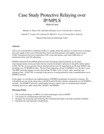
MPLS VPN TechnologyMPLS VPN Connection ModelPPPEPEVPN Backbone IGPPPMP iBGP SessionPE RoutersP Routers Edge routers Use MPLS with P routers P routers are in the core of the MPLScloud P routers do not need to runBGP and doesn’t need to haveany VPN knowledge Forward packets by lookingat labels P and PE routers share acommon IGP Uses IP with CE routers Connects to both CE and P routersDistribute VPN information throughMP BGP to other PE router with VPN IPv4 addresses, extended community,label 2007 Cisco Systems, Inc. All rights reserved.10
MPLS VPN TechnologySeparate Routing Tables at PEVPN 2CEEBGP, OSPF, RIPv2, StaticCEVPN 1PEMPLS Backbone IGP (OSPF, ISIS)VRF Routing TableThe Global Routing Table Routing (RIB) and forwarding table(CEF) associated with one or moredirectly connected sites (CEs) Populated by the IGPwithin MPLS backbone The routes the PE receives from CErouters are installed in the appropriateVRF routing table(s)blue VRF routing table orgreen VRF routing table 2007 Cisco Systems, Inc. All rights reserved.11
MPLS VPN TechnologyVirtual Routing and Forwarding Instance (1)VPN 2CEVRFGreenPEEBGP, OSPF, RIPv2, StaticCEVPN 1VRF BlueMPLS Backbone IGP (OSPF, ISIS) What’s a VRF ? Associates to one or more interfaces on PEPrivatize an interface i.e., coloring of the interface Has its own routing table and forwarding table (CEF) VRF has its own instance for the routing protocol(static, RIP, BGP, EIGRP, OSPF) CE router runs standard routing software 2007 Cisco Systems, Inc. All rights reserved.12
MPLS VPN TechnologyVirtual Routing and Forwarding Instance (2)VPN 2CEEBGP, OSPF, RIPv2, StaticCEVPN 1PEMPLS Backbone IGP (OSPF, ISIS) PE installs the routes, learned from CE routers,in the appropriate VRF routing table(s) PE installs the IGP (backbone) routes in the globalrouting table VPN customers can use overlapping IP addresses 2007 Cisco Systems, Inc. All rights reserved.13
MPLS VPN Technology:Control Plane8 Bytes4 Bytes1:110.1.1.0RDVPNv4IPv48 BytesRoute Target3 BytesLabelMP REACH NLRI attribute withinMP BGP UPDATE messageLet’s Discuss: Route Distinguisher (RD); VPNv4 route Route Target (RT) Label 2007 Cisco Systems, Inc. All rights reserved.14
MPLS VPN Control PlaneMP BGP Update Components: VPNv4 Address8 Bytes4 Bytes1:110.1.1.0RDVPNv4IPv48 BytesRoute Target3 BytesLabelMP IBGP update with RD, RT, and label To convert an IPv4 address into a VPNv4 address,RD is appended to the IPv4 address i.e. 1:1:10.1.1.0Makes the customer’s IPv4 route globally unique Each VRF must be configured with an RD at the PERD is what that defines the VRF 2007 Cisco Systems, Inc. All rights reserved.!ip vrf v1rd 1:1!15
MPLS VPN Control PlaneMP BGP Update Components: Route Target8 Bytes4 Bytes8 Bytes1:110.1.1.02:2RDVPNv4IPv4Route Target3 BytesLabelMP IBGP update with RD, RT, and Label Route target (RT): Identifies the VRF for the receivedVPNv4 prefix. It is an 8 byte extended community (aBGP attribute) Each VRF is configured with RT(s) at the PERT helps to color the prefix 2007 Cisco Systems, Inc. All rights reserved.!ip vrf v1route target import 1:1route target export 1:2!16
MPLS VPN Control PlaneMP BGP Update Components: Label8 Bytes4 Bytes8 Bytes3 Bytes1:110.1.1.02:250RDVPNv4IPv4Route TargetLabelMP IBGP update with RD, RT, and label The Label (for the VPNv4 prefix) is assigned only by the PE whoseaddress is the next hop attributePE routers rewrite the next hop with their own address (loopback)“Next hop self” towards MP iBGP neighbors by default PE addresses used as BGP next hop must be uniquely known inthe backbone IGPDo Not Summarize the PE Loopback Addresses in the Core 2007 Cisco Systems, Inc. All rights reserved.17
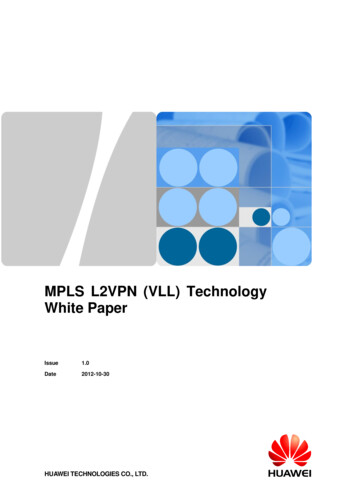
MPLS VPN Technology: Control PlaneMP BGP UPDATE Message Capture This capture mighthelp to visualize howthe BGP UPDATEmessage advertisingVPNv4 routes looklike. Notice the PathAttributes.RouteTarget 3:3MP REACHNLRI1:1:200.1.62.4/30 2007 Cisco Systems, Inc. All rights reserved.18
MPLS VPN Control Plane:Putting It All Together3Site 1CE110.1.1.0/2410.1.1.0/24Next Hop CE 1PE11MP iBGP Update:RD:10.1.1.0Next Hop PE 1RT Green, Label 100PPPPSite 2CE2PE2MPLS Backbone1. PE1 receives an IPv4 update (eBGP,OSPF,EIGRP)2. PE1 translates it into VPNv4 addressAssigns an RT per VRF configurationRewrites next hop attribute to itselfAssigns a label based on VRF and/or interface3. PE1 sends MP iBGP update to other PE routers 2007 Cisco Systems, Inc. All rights reserved.19
MPLS VPN Control Plane:Putting It All Together3Site 1CE110.1.1.0/2410.1.1.0/24Next Hop CE 1PE11MP iBGP Update:RD:10.1.1.0Next Hop PE 1RT Green, Label 100PPPP10.1.1.0/24Next Hop PE 25Site 2CE2PE2MPLS Backbone1. PE2 receives and checks whether the RT green is locallyconfigured within any VRF, if yes, then2. PE2 translates VPNv4 prefix back into IPv4 prefix,Installs the prefix into the VRF routing tableUpdates the VRF CEF table with label 100 for 10.1.1.0/24Advertise this IPv4 prefix to CE2 (EBGP, OSPF, EIGRP) 2007 Cisco Systems, Inc. All rights reserved.20
MPLS VPN Technology:Forwarding PlaneSite 2Site 110.1.1.0/24CE110.1.1.0/24Next Hop CE 1CE2PE1P1PGlobal Routing/Forwarding TableDest Next HopPE2 P1, Label: 50P2PE2PVRF Green Forwarding TableDest NextHop10.1.1.0/24 PE1, label: 100Global Routing/Forwarding TableDest Next HopPE1 P2, Label: 25The Global Forwarding Table(show ip cef)VRF Forwarding Table(show ip cef vrf vrf ) PE routers store IGP routes PE routers store VPN routes Associated labels Associated labels Label distributed through LDP/TDP Labels distributed through MP BGP 2007 Cisco Systems, Inc. All rights reserved.21
MPLS VPN Technology:Forwarding PlaneSite 2Site PP10.1.1.110.1.1.12510010.1.1.1 PE2 imposes TWO labels for each packet going to theVPN destination 10.1.1.1 The top label is LDP learned and derived from an IGP routeRepresents LSP to PE address (exit point of a VPN route) The second label is learned via MP BGPCorresponds to the VPN address 2007 Cisco Systems, Inc. All rights reserved.22
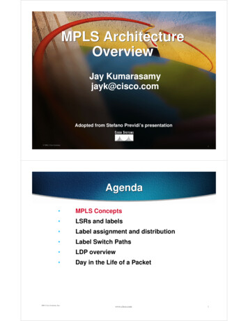
MPLS VPN Technology: Control PlaneMPLS Packet Capture This capturemight be helpfulif you nevercaptured anMPLS packetbefore.Ethernet HeaderOuter LabelInner LabelIP packet 2007 Cisco Systems, Inc. All rights reserved.23
Agenda MPLS VPN ExplainedMPLS VPN Services1.2.3.4.5.6.7. Providing Load Shared Traffic to the Multihomed VPN SitesProviding Hub and Spoke Service to the VPN CustomersProviding Internet Access Service to VPN CustomersProviding VRF Selection Based ServicesProviding Remote Access MPLS VPNProviding VRF Aware NAT ServicesProviding MPLS VPN over IP Transport & Multi VRF CE ServicesBest PracticesConclusion 2007 Cisco Systems, Inc. All rights reserved.24
MPLS VPN Services:1. Loadsharing for the VPN TrafficRRPE11PE2CE1171.68.2.0/24CE2PE12Site AMPLS BackboneSite BRoute Advertisement VPN sites (such as Site A) could be multihomed VPN customer may demand the traffic (to themultihomed site) be loadshared 2007 Cisco Systems, Inc. All rights reserved.25
MPLS VPN Services:1. Loadsharing for the VPN Traffic: Cases1 CE 2 PEsRRPE11PE2CE1171.68.2.0/24CE2PE12Site ASite BMPLS BackboneTraffic Flow2 CEs 2 PEsCE1171.68.2.0/24CE2RRPE11PE2PE12MPLS BackboneSite ACE2Site BTraffic Flow 2007 Cisco Systems, Inc. All rights reserved.26
MPLS VPN Services:1. Loadsharing for the VPN Traffic: Deployment How to deploy the loadsharing? Configure unique RD per VRF per PE for multihomedsite/interfaces Enable BGP multipath within the relevant BGP VRFaddress family at remote/receiving PE2 (why PE2?)1ip vrf greenrd 300:11route target both 1:12RRPE11router bgp 1address family ipv4 vrf greenmaximum paths eibgp 2PE2CE1CE2171.68.2.0/241Site Aip vrf greenrd 300:12route target both 1:1 2007 Cisco Systems, Inc. All rights reserved.PE12MPLS Backbone1Site Bip vrf greenrd 300:13route target both 1:127
MPLS VPN Services:1. Loadsharing for the VPN TrafficRRPE11Route AdvertisementPE2CE1CE2171.68.2.0/24Site APE12MPLS BackboneSite B RR must advertise all the paths learned via PE11 and PE12 to theremote PE routersPlease note that without ‘unique RD per VRF per PE’, RR would advertise onlyone of the received paths for 171.68.2.0/24 to other PEs. Watch out for the increased memory consumption(within BGP) due to multipaths at the PEs “eiBGP multipath” implicitly provides both eBGP andiBGP multipath for VPN paths 2007 Cisco Systems, Inc. All rights reserved.28
Agenda MPLS VPN ExplainedMPLS VPN Services1.2.3.4.5.6.7. Providing Load Shared Traffic to the Multihomed VPN SitesProviding Hub and Spoke Service to the VPN CustomersProviding Internet Access Service to VPN CustomersProviding VRF Selection Based ServicesProviding Remote Access MPLS VPNProviding VRF Aware NAT ServicesProviding MPLS VPN over IP Transport & Multi VRF CE ServicesBest PracticesConclusion 2007 Cisco Systems, Inc. All rights reserved.29
MPLS VPN Services:2. Hub and Spoke Service to the VPN Customers Traditionally, VPN deployments are Hub and SpokeSpoke to spoke communication is via Hub site only Despite MPLS VPN’s implicit any to any, i.e,full mesh connectivity, Hub and Spoke servicecan easily be offeredDone with import and export of route target (RT) values 2007 Cisco Systems, Inc. All rights reserved.30
MPLS VPN Services:2. Hub and Spoke Service: Configurationrouter bgp ASN address family ipv4 vrf HUB OUTneighbor CE as overrideip vrf green spoke1description VRF for SPOKE Ard 300:111route target export 1:1route target import 2:2Spoke A171.68.1.0/24CE SAip vrf HUB OUTdescription VRF for traffic from HUBrd 300:11route target import 1:1PE SAEth0/0.1PE HubSpoke B171.68.2.0/24CE SBPE SBip vrf green spoke2description VRF for SPOKE Brd 300:112route target export 1:1route target import 2:2 2007 Cisco Systems, Inc. All rights reserved.Eth0/0.2MPLS VPN Backboneip vrf HUB INdescription VRF for traffic to HUBrd 300:12route target export 2:2router bgp ASN address family ipv4 vrf HUB INneighbor CE allowas in 231
MPLS VPN Services:2. Hub and Spoke Service: Configuration If BGP is used end to end, then as override andallowas in knobs must be used at the PE HubOtherwise AS PATH looping will occur If the spoke sites only need the default route from thehub site, then it is possible to use a single interfacebetween PE hub and CE hub (instead of two interfacesas shown on the previous slide)Let CE hub router advertise the default or aggregateAvoid generating a BGP aggregate at the PE 2007 Cisco Systems, Inc. All rights reserved.32
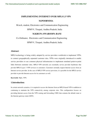
MPLS VPN Services:2. Hub and Spoke Service: Control PlaneMPLS BackboneSpoke A171.68.1.0/24CE SAPE SAMP iBGP171.68.1.0/24Label 40Route Target 1:1VRF RT and LFIB at PE SA171.68.0.0/16 PE Hub35171.68.1.0/24 CE SAMP iBGP171.68.0.0/16Label 35Route Target 2:2VRF RT and LFIB at PE SB171.68.0.0/16 PE Hub35171.68.2.0/24 CE SB171.68.2.0/24Spoke BCE SBVRF HUB OUT RT and LFIBDestinationNextHop Label171.68.1.0/24PE SA 40171.68.2.0/24PE SB 50PE SBMP iBGP171.68.2.0/24Label 50Route Target 1:1VRF HUB OUTPE HubVRF HUB INVRF HUB IN Routing TableDestinationNextHop171.68.0.0/16CE H1 All traffic between spokes must pass through the hub/central siteHub site could offer FireWall, NAT like applications Two VRF solutions at the PE hub:VRF HUB OUT would have knowledge of every spoke routesVRF HUB IN only have a 171.68.0.0/16 route and advertise that to spoke PEs Import and export route target within a VRF must be different 2007 Cisco Systems, Inc. All rights reserved.33
MPLS VPN Services:2. Hub and Spoke Service: Forwarding PlaneThis is how the spoke to spoke traffic flows MPLS Backbone171.68.1.1Spoke A171.68.1.0/24CE SAPE SAL240171.68.1.1VRF HUB OUTPE HubSpoke B171.68.2.0/24CE SBPE SBL135171.68.1.1VRF HUB IN171.68.1.1L1 is the label to get to PE HubL2 is the label to get to PE SA 2007 Cisco Systems, Inc. All rights reserved.34
MPLS VPN Services:2. Hub and Spoke Service: Half Duplex VRF When do we need Half duplex VRF? If more than one spoke router (CE) connects to thesame PE router within the single VRF, then suchspokes can reach other without needing the HubThis defeats the purpose of doing Hub and Spoke Half duplex VRF is the answer.Half duplex VRF is specific to dial users i.e.,virtual template It requires two VRFs on the PE routerUpstream VRF for Spoke Hub communicationDownstream VRF for Spoke Hub communication 2007 Cisco Systems, Inc. All rights reserved.35
MPLS VPN Services:2. Hub and Spoke Service: Half Duplex VRFip vrf red vrfdescription VRF – upstream flowrd 300:111route target import 2:2Spoke A171.68.1.0/24ip vrf blue vrfdescription VRF – downstream flowrd 300:112route target export 1:1ip vrf HUB OUTdescription VRF for traffic from HUBrd 300:11route target import 1:1CE SAPE SAMPLS BackbonePE HubSpoke BInt virtual template1171.68.2.0/24CE SB .ip vrf forward red vrf downstream blue vrf Upstream VRFDownstream VRFip vrf HUB INdescription VRF for traffic to HUBrd 300:12route target export 2:2PE SA installs the spoke routes only in downstream VRF i.e. blue VRFPE SA forwards the incoming IP traffic (from Spokes) using theupstream VRF i.e. red vrf routing table 2007 Cisco Systems, Inc. All rights reserved.36
Agenda MPLS VPN ExplainedMPLS VPN Services1.2.3.4.5.6.7. Providing Load Shared Traffic to the Multihomed VPN SitesProviding Hub and Spoke Service to the VPN CustomersProviding Internet Access Service to VPN CustomersProviding VRF Selection Based ServicesProviding Remote Access MPLS VPNProviding VRF Aware NAT ServicesProviding MPLS VPN over IP Transport & Multi VRF CE ServicesBest PracticesConclusion 2007 Cisco Systems, Inc. All rights reserved.37
MPLS VPN Services3. Internet Access Service to VPN Customers Internet access service could be provided as anothervalue added service to VPN customers Security mechanism must be in place at both providernetwork and customer networkTo protect from the Internet vulnerabilities VPN customers benefit from the single point of contactfor both Intranet and Internet connectivity 2007 Cisco Systems, Inc. All rights reserved.38
MPLS VPN Services3. Internet Access: Different Methods of Service Four ways to provide the Internet service1. VRF specific default route with “global” keyword2. Separate PE CE sub interface (non VRF)3. Extranet with Internet VRF4. VRF aware NAT 2007 Cisco Systems, Inc. All rights reserved.39
MPLS VPN Services3. Internet Access: Different Methods of Service1. VRF specific default route1.1 Static default route to move traffic from VRF to Internet(global routing table)1.2 Static routes for VPN customers to move traffic from Internet (global routingtable) to VRF2. Separate PE CE sub interface (non VRF)May run BGP to propagate Internet routes between PE and CE3. Extranet with Internet VRFVPN packets never leave VRF context; issue with overlapping VPN address4. Extranet with Internet VRF along with VRF aware NATVPN packets never leave VRF context; works well with overlappingVPN address 2007 Cisco Systems, Inc. All rights reserved.40
MPLS VPN Services:3.1 Internet Access: VRF Specific Default Route (Config)Site1171.68.0.0/16CE1MPLS BackboneInternetSO PE1192.168.1.2PE1#ip vrf VPN Ard 100:1route target both 100:1ASBRPInterface Serial0ip address 192.168.10.1 255.255.255.0ip vrf forwarding VPN ARouter bgp 100no bgp default ipv4 unicastredistribute staticneighbor 192.168.1.1 remote 100neighbor 192.168.1.1 activateneighbor 192.168.1.1 next hop selfneighbor 192.168.1.1 update source loopback0ip route vrf VPN A 0.0.0.0 0.0.0.0 192.168.1.1 globalip route 171.68.0.0 255.255.0.0 Serial0 2007 Cisco Systems, Inc. All rights reserved.192.168.1.1Internet GW A default route, pointing to theASBR, is installed into the siteVRF at each PE The static route, pointing to theVRF interface, is installed in theglobal routing table andredistributed into BGP41
MPLS VPN Services:3.1 Internet Access: VRF Specific Default Route (Forwarding)Site1171.68.0.0/16IP PacketD 171.68.1.1Label 30IP PacketD Cisco.comIP PacketD Cisco.comIP PacketD Cisco.comSe0PE1192.168.1.2PE2PSO192.168.1.1Label 35IP PacketD 171.68.1.1Global Routing/FIB TableDestinationLabel/Interface192.168.1.1/32 Label 30171.68.0.0/16Serial 0VRF Routing/FIB TableDestinationLabel/Interface0.0.0.0/0 192.168.1.1 (global)Site 1Serial 0MPLS BackboneInternetIP PacketD 171.68.1.1Global Table and LFIBDestinationLabel/Interface192.168.1.2/32Label 35171.68.0.0/16192.168.1.2InternetSerial 0ProsConsDifferent Internet gatewayscan be used for different VRFsPE routers need not to holdthe Internet tableSimple configurationUsing default route for Internetrouting does NOT allow anyother default route for intra VPNrouting Increasing size of globalrouting table by leaking VPNroutesStatic configuration (possibilityof traffic blackholing) 2007 Cisco Systems, Inc. All rights reserved.42
MPLS VPN Services3.2 Internet Access1. VRF specific default route1.1 Static default route to move traffic from VRF to Internet(global routing table)1.2 Static routes for VPN customers to move traffic from Internet (globalrouting table) to VRF2. Separate PE CE sub interface (non VRF)May run BGP to propagate Internet routes between PE and CE3. Extranet with Internet VRFVPN packets never leave VRF context; overlapping VPN addresses could bea problem4. Extranet with Internet VRF along with VRF aware NATVPN packets never leave VRF context; works well with overlappingVPN addresses 2007 Cisco Systems, Inc. All rights reserved.43
3.2 Internet Access Service to VPN CustomersUsing Separate Sub Interface (Config)Site1MPLS Backbone171.68.0.0/16CE1InternetInternetBGP 4Se0.2PE1 192.168.1.2Se0.1ip vrf VPN Ard 100:1route target both 100:1Interface Serial0.1ip vrf forwarding VPN Aip address 192.168.20.1 255.255.255.0frame relay interface dlci 100!Interface Serial0.2ip address 171.68.10.1 255.255.255.0frame relay interface dlci 200!Router bgp 100no bgp default ipv4 unicastneighbor 171.68.10.2 remote as 502 2007 Cisco Systems, Inc. All rights reserved.ASBR192.168.1.1PInternet GW One sub interface for VPN routingassociated to a VRF Another sub interface for Internetrouting associated to the global routingtable Could advertise full Internet routes or adefault route to CE The PE will need to advertise VPNroutes to the Internet (via globalrouting table)44
Internet Access Service to VPN Customers3.2 Using Separate Sub Interface (Forwarding)Site1MPLS Backbone171.68.0.0/16IP PacketD Cisco.comLabel 30InternetInternetIP PacketD Cisco.comS0.2IP PacketD Cisco.comPE2PE1 192.168.1.2S0.1PCE Routing TableVPN RoutesSerial0.1Internet RoutesSerial0.2PE Global Table and FIBInternet Routes192.168.1.1192.168.1.1Label 30 2007 Cisco Systems, Inc. All rights reserved.192.168.1.1PE Internet GWProsConsCE could dual home andperform optimal routingPE to hold full Internet routesTraffic separation doneby CEBGP complexities introducedin CE; CE1 may need toaggregate to avoid AS PATHlooping45
Internet Access Service3.3 Extranet with Internet VRF The Internet routes could be placed within the VRF atthe Internet GW i.e. ASBR VRFs for customers could ‘extranet’ with the InternetVRF and receive either default, partial or full Internetroutes Be careful if multiple customer VRFs, at the same PE,are importing full Internet routes Works well only if the VPN customers don’t haveoverlapping addresses 2007 Cisco Systems, Inc. All rights reserved.46
Internet Access Service3.4 Internet Access Using VRF Aware NAT If the VPN customers need Internet access withoutInternet routes, then VRF aware NAT can be used atthe Internet GW i.e. ASBR The Internet GW doesn’t need to have Internet routeseither Overlapping VPN addresses is no longer a problem More in the “VRF aware NAT” slides 2007 Cisco Systems, Inc. All rights reserved.47
Agenda MPLS VPN ExplainedMPLS VPN Services1.2.3.4.5.6.7. Providing Load Shared Traffic to the Multihomed VPN SitesProviding Hub and Spoke Service to the VPN CustomersProviding Internet Access Service to VPN CustomersProviding VRF Selection Based ServicesProviding Remote Access MPLS VPNProviding VRF Aware NAT ServicesProviding MPLS VPN over IP Transport & Multi VRF CE ServicesBest PracticesConclusion 2007 Cisco Systems, Inc. All rights reserved.48
MPLS VPN Service4. VRF Selection The common notion is that the VRF must be associatedto an interface “VRF selection” breaks this association and associatemultiple VRFs to an interface Each packet on the PE CE interface could be handled(based on certain criteria) via different VRF routingtablesCriteria such as source/dest IP address, ToS, TCP port, etc.specified via route map Voice and data can be separated out into differentVRFs at the PE; Service enabler 2007 Cisco Systems, Inc. All rights reserved.49
MPLS VPN Service4. VRF Selection: Based on Source IP AddressGlobal Interface33.3.14.1CableSetupPE1CE1RRVRF InterfacesMPLS Backbone(Cable Company)Se0/0PE2VPN Brown33.3.0.0/16VPN Blue44.3.0.0/1666.3.1.25Traffic Flows44.3.12.1ip vrf brownrd 3000:111route target export 3000:1route target import 3000:1!ip vrf bluerd 3000:222route target export 3000:2route target import 3000:2!ip vrf greenrd 3000:333route target export 3000:3route target import 3000:3interface Serial0/0ip address 215.2.0.6 255.255.255.252ip policy route map PBR VRF Selectionip receive brownip receive blueip receive greenaccess list 40 permit 33.3.0.0 0.0.255.255access list 50 permit 44.3.0.0 0.0.255.255access list 60 permit 66.3.0.0 0.0.255.255 2007 Cisco Systems, Inc. All rights reserved.VPN Green66.3.0.0/16route map PBR VRF Selection permit 10match ip address 40set vrf brownroute map PBR VRF Selection permit 20match ip address 50set vrf blueroute map PBR VRF Selection permit 30match ip address 60set vrf green50
Agenda MPLS VPN ExplainedMPLS VPN Services1.2.3.4.5.6.7. Providing Load Shared Traffic to the Multihomed VPN SitesProviding Hub and Spoke Service to the VPN CustomersProviding Internet Access Service to VPN CustomersProviding VRF Selection Based ServicesProviding Remote Access MPLS VPNProviding VRF Aware NAT ServicesProviding MPLS VPN over IP Transport & Multi VRF CE ServicesBest PracticesConclusion 2007 Cisco Systems, Inc. All rights reserved.51
MPLS VPN Service5. Remote Access Service Remote access users i.e. dial users, IPSec users coulddirectly be terminated in VRFPPP users can be terminated into VRFsIPSec tunnels can be terminated into VRFs Remote access services integration with MPLS VPNopens up new opportunities for providers and VPNcustomers 2007 Cisco Systems, Inc. All rights reserved.52
MPLS VPN Service5. Remote Access Service: IPSec to MPLS VPNBranchOfficeSP Shared NetworkAccessSP AAACustomerAAAPE IPSecAggregatorSOHOInternetLocal orDirectDial ISPVPN APEIP/MPLS/Layer 2Based NetworkPECable/DSL/ISDN ISPRemote Users/TelecommutersIPCorporate IntranetPECustomer Ahead officeVPN BCustomer BVPN ACisco IOS VPNRouters or CiscoClient 3.x or higherIPSec Session 2007 Cisco Systems, Inc. All rights reserved.Customer ABranch OfficeMPLS VPNVPN CCustomer CIP53
Agenda MPLS VPN ExplainedMPLS VPN Services1.2.3.4.5.6.7. Providing Load Shared Traffic to the Multihomed VPN SitesProviding Hub and Spoke Service to the VPN CustomersProviding Internet Access Service to VPN CustomersProviding VRF Selection Based ServicesProviding Remote Access MPLS VPNProviding VRF Aware NAT ServicesProviding MPLS VPN over IP Transport & Multi VRF CE ServicesBest PracticesConclusion 2007 Cisco Systems, Inc. All rights reserved.54
MPLS VPN Services6. VRF Aware NAT Services VPN customers could be using ‘overlapping’ IP addressi.e. 10.0.0.0/8 Such VPN customers must NAT their traffic beforeusing either “Extranet” or “Internet” or any shared*services PE is capable of NATting the VPN packets (eliminatingthe need for an extra NAT device)* VoIP, Hosted Content, Management, etc. 2007 Cisco Systems, Inc. All rights reserved.55
MPLS VPN Services6. VRF Aware NAT Services Typically, inside interface(s) connect to private addressspace and outside interface(s) connect to globaladdress spaceNAT occurs after routing for traffic from inside to outsideinterfacesNAT occurs before routing for traffic from outside to insideinterfaces Each NAT entry is associated with the VRF Works on VPN packets in the following switch paths:IP IP, IP MPLS and MPLS IP 2007 Cisco Systems, Inc. All rights reserved.56
MPLS VPN Services:6. VRF Aware NAT Services: Internet Access10.1.1.0/24PE11CE1PGreen VPN Site10.1.1.0/24CE2MPLS BackbonePE ASBR.1217.34.42.2InternetPE12IP NAT InsideBlue VPN SiteIP NAT Outsideip vrf greenrd 3000:111route target both 3000:1ip vrf bluerd 3000:222route target both 3000:2ip nat pool pool green 24.1.1.0 24.1.1.254 prefix length 24router bgp 3000address family ipv4 vrf greennetwork 0.0.0.0address family ipv4 vrf bluenetwork 0.0.0.0ip access list standard vpn to natpermit 10.1.1.0 0.0.0.255VRF Specific Config 2007 Cisco Systems, Inc. All rights reserved.ip nat pool pool blue 25.1.1.0 25.1.1.254 prefix length 24ip nat inside source list vpn to nat pool pool green vrf greenip nat inside source list vpn to nat pool pool blue vrf blueip route vrf green 0.0.0.0 0.0.0.0 217.34.42.2 globalip route vrf blue 0.0.0.0 0.0.0.0 217.34.42.2 globalVRF Aware NAT Specific Config57
MPLS VPN Services:6. VRF Aware NAT Services: Internet Access10.1.1.0/24CE1Green VPN Site10.1.1.0/24Src 10.1.1.1Dest InternetIP PacketCE2Blue VPN SiteMPLS BackboneLabel 30Src 10.1.1.1Dest InternetPE11PE12Src 10.1.1.1Dest InternetPE ASBRPSrc 24.1.1.1Dest InternetInternetSrc 25.1.1.1Dest InternetIP PacketLabel 40Src 10.1.1.1Dest InternetMPLS Packet PE ASBR removes the label from thereceived MPLS packets per LFIB Performs NAT on the resulting IP packetsVRF IP Source10.1.1.110.1.1.1Traffic FlowsNAT TableGlobal IP VRF Table Id24.1.1.1green25.1.1.1blue Forwards the packet to the internet Returning packets are NATed and put backin the VRF context and then routed This is also one of the ways to provide Internet access to VPNcustomers with or without overlapping addresses 2007 Cisco Systems, Inc. All rights reserved.58
Agenda MPLS VPN Explained MPLS VPN Services1.Providing Load Shared Traffic to the Multihomed VPN Sites2.Providing Hub and Spoke Service to the VPN Customers3.Providing Internet Access Service to VPN Customers4.Providing VRF Selection Based Services5.Providing Remote Access MPLS VPN6.Providing VRF Aware NAT Services7.Providing MPLS VPN over IP Transport & Multi VRF CE Services Best Practices Conclusion 2007 Cisco Systems, Inc. All rights reserved.59
MPLS VPN Services:7. Providing MPLS/VPN over IP Transport What if the core (P) routers are not capable of runningMPLS MPLS/VPN (rfc2547) can be deployed using IPtransportNO LDP anywhere Instead of using the MPLS label to reach the next hop,an IP tunnel is used.IP tunnel could be L2TPv3, GRE etc. MPLS labels are still allocated for the VPN prefix andused only by the PE routers 2007 Cisco Systems, Inc. All rights reserved.60
MPLS VPN Services:7. Providing Multi VRF CE Service Is it possible for an IP router to keep multiple customerconnections separated ?Yes, “multi VRF CE” aka vrf lite is the answer. “Multi VRF CE” provides multiple virtual routing tables (andforwarding tables) per customer at the CE routerNot a feature but an application based on VRF implementationAny routing protocol that is supported by normal VRF can be used in a Multi VRF CE implementation There is no MPLS functionality on the CE, no label exchangebetween the CE and any router (including PE) 2007 Cisco Systems, Inc. All rights reserved.61
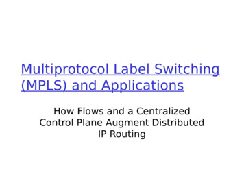
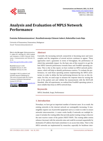
MPLS VPN Services:7. Providing Multi VRF CE ServiceOne Deployment Model—Extending MPLS/VPNClientsVrf greenClientsSubInterfaceLink *Vrf redMulti VRFCE RouterMPLSNetworkPERouterVrf greenPERouterVrf redSubInterface Link – Any Inter
MPLS VPN Explained MPLS VPN Services 1. Providing Load Shared Traffic to the Multihomed VPN Sites 2. Providing Hub and Spoke Service to the VPN Customers 3. Providing Internet Access Service to VPN Customers 4. Providing VRF Selection Based Services 5. Providing Remote Access MPLS VPN 6.