Transcription
Manual Number9017782Revision PJanuary 6, 2022
FOREWORDThis manual provides information intended for use by persons who, in accordance withcurrent regulatory requirements, are qualified to install this equipment. If further information isrequired, please contact:Mid-Continent Instruments and AvionicsAttn: Customer Service Dept.9400 E. 34th Street N.Wichita, KS 67226 USAPH (316) 630-0101FX (316) 630-0723www.mcico.comWe welcome your comments concerning this manual. Although every effort has been madeto keep it free of errors, some may occur. When reporting a specific problem, please describeit briefly and include the manual part number, the paragraph/figure/table reference and thepage number. Send your comments to:Mid-Continent Instruments and AvionicsAttn: Technical Publications9400 E. 34th Street N.Wichita, KS 67226 USAPH (316) 630-0101FX (316) 630-0723ks.customerservice@mcico.comAll products produced by Mid-Continent Instrument Co., Inc., including those identified asMid-Continent Instruments and Avionics or True Blue Power, are designed and manufacturedin Wichita, KS, USA.Download the currentversion of thisinstallation manualusing yoursmartphone or tablet. Copyright 2019Mid-Continent Instrument Co., Inc.Manual Number 9017782Revision P, January 6, 20221
TABLE OF CONTENTSSECTION 11.11.21.31.488101112GENERAL INFORMATIONPARTS LISTCABLE HARNESSPITOT / STATIC CONNECTIONSMOUNTINGINSTALLATION COMPLETION121212151717OPERATION20USER INTERFACEPRE-FLIGHT MODEFLIGHT MODEEMERGENCY OPERATIONCONFIGURATION SETUPSECTION 55.15.2PRE-INSTALLATION CONSIDERATIONSINSTALLATIONSECTION 44.14.24.34.44.54567EQUIPMENT LOCATIONLIMITATIONSMODIFICATIONSECTION 33.13.23.33.43.53.64INTRODUCTIONTECHNICAL SPECIFICATIONSARINC DATA LABELSIMPORTANT SAFETY INFORMATIONSECTION 22.12.22.3GENERAL DESCRIPTION2020223840CONFORMANCE62INSTRUCTIONS FOR CONTINUED AIRWORTHINESSENVIRONMENTAL QUALIFICATION STATEMENTManual Number 9017782Revision P, January 6, 202226269
REVISION 25/2019N07/02/2020P01/06/2022Manual Number 9017782DetailEngineering release.Initial release.Updates implemented.Remove “Pending” from certification table 1.4. UpdateSection 2.4. Added panel orientation graphic to Figure 2.1.Updated lightning callout to H3B3L3. Various minorcorrections. Add Figure 3.6. Consolidate Figures 3.10/3.11and Figures 3.12/3.13.Updated logos to include registered trademarks.Updated screen captures to reflect software version 1.0.1.Update DO-160 qualification to include helicopter vibration.Various minor corrections.Incorporated changes associated with software version1.0.3. Added label 204 to ARINC outputs. Added BaroSync information to Section 3.3.1.2.Added Mod 1 ConfigurationIncorporated changes associated with software version1.0.4. Added labels 014 and 320 to ARINC inputs. AddedHeading Operation to Section 3.3.1.1.1. Added ConfigurePreview to Section 4.1.1. Added VNE Configuration toSection 4.4.5. Added Heading Display to Section 4.5.Added Calibrate Pressures to Section 4.6. Updated screencaptures where applicable.Updated Section 5.1 to include revised software updateprocedure.Incorporated changes associated with software version1.0.5.Added TSO C6e and support information for use of MD32Magnetometer. ARINC pass-through feature. Updatedpinout. Add patent reference.Added -7 and -8 configurations and Type 2 batteryinformation. Added SSEC ARINC label.Revised limitations associated with -45 C operation.Corrected ARINC labels 234, 235.Updated style and brand to meet Marketing andEngineering guidelines.Moved Operation from Section 3 to Section 4.Updated images to reflect most current display. AddedSection 4.5.8, Configure Auto-Off.Updated Section 3.2 and 3.4 with o-ring replacement info.Revision P, January 6, ASDLRDLR
SECTION 1 GENERAL DESCRIPTION1.1INTRODUCTIONThe model MD302 series SAM Standby Attitude Module is a self-contained situational awarenessinstrument that provides aircraft attitude, altitude, airspeed, and slip indication, plus availableheading data with the optionally installed MD32 Magnetometer. The compact and innovative designof the MD302 is specifically developed for maximum flexibility for installation in retrofit or moderninstrument panels. Its size, extra-wide viewing angle and AnyWayTM selectable orientation allows itto be installed almost anywhere in the instrument panel and in less space than traditional, 2-inchmechanical standby or primary flight instruments.Regardless of the aircraft you are flying, the MD302 is a great fit. With a 10 to 32 volt DC inputrange, the unit will work with 14 or 28V aircraft electrical buses and the selectable lighting inputallows operation with 5, 14 or 28V lighting systems. The operation and certification of the MD302make it well suited for Part 23 and 25 fixed-wing applications as well as Part 27 and 29 rotorcraft.The MD302 provides critical flight and situational data to the pilot and crew under anycircumstances you are likely to encounter. The design is built around a solid-state electronic sensorarray for high reliability and contains an integral and rechargeable battery that can power the unitfor up to two hours if main aircraft power is lost. The dual, high-resolution LCD display uses smoothgraphics, daylight-readable brightness and a configurable lighting response curve to ensure optimalvisibility in all conditions.The user interface of the product allows for simple, intuitive operation using a single push-and-turncontrol knob that easily navigates through the user options and menu screens. The interactivity ofthe unit means that it can receive and transmit ARINC 429 data communications. Functionaloutputs of attitude, altitude, and airspeed can be used for monitoring or backup information whilebaro input data can be received and will synchronize the baro setting with the primary system toeliminate redundant task loading for the pilot.The MD302 is an excellent complement to your avionics suite as a reliable and state-of-the-artinstrument that is an essential part of any instrument panel.Manual Number 9017782Revision P, January 6, 20224
1.2TECHNICAL SPECIFICATIONSElectrical AttributesInput Voltage:Input Power:(nominal)(maximum)Output Power:Lighting Input:Input Data:Output Data:Battery Backup:Type 1 (Lithium-ion)Type 2 (Nickel Metal Hydride)10-32 VDC6 watts (0.22A @ 28VDC)40 watts max (when charging and heating battery display)Reserved for MD32 Remote Magnetometer (pin 11)5, 14, or 28VDC or automatic photocell controlARINC 429 (see Table 1.1)ARINC 429 (see Table 1.1);discrete valid signal to ground; invalid signal is open (pin 2)3 cells in series x 3.3V x 1.0Ah 9.9 Watt-hours5 cells in series x 1.2V x 2.0Ah 12 Watt-hoursPhysical AttributesWeight:Dimensions:(without connectors, mates & knob)Mating Connectors:1.6 pounds (0.73 kg)Bezel:2.37” x 5.50” x 0.33” (HxWxD)Chassis:2.31” x 3.16” x 4.84” (HxWxD)15-pin D-Sub with Configuration ModulePneumatic fittingsPanel mount from front;uses (4) #6-32 cap screws and Nutplate (included)Mounting:Performance LimitsAttitude:Pitch AnglePitch RateRoll AngleRoll tionsCertifications:No limits (360 )300 per second maxNo limits (360 )300 per second max-1,500 to 55,000 feet28.00 to 31.00 inches of mercury20 to 500 knots(available in meters)(available in mbar)(available in mph or kph)Environmental Qualification:Software Qualification:Complex Hardware Qualification:Lithium-ion Qualification:FAA TSO-C2d (Type B), C3e, C4c, C6e, C10b, C106, C113a,C179aEASA ETSO-C2d, C3d, C4c, C6e, C10b, C106, C113, C179aRTCA DO-160G (details listed in Section 5.2)RTCA DO-178B, Design Assurance Level ARTCA DO-254, Design Assurance Level AUL 1642; RTCA DO-311; RTCA DO-347 (partial)RightsU.S. Patent No.:9,739,611Manual Number 9017782Revision P, January 6, 20225
1.3ARINC DATA LABELSAll labels are defined as Equipment ID 038 in BNR format. High and Low speed options for ARINCoutputs are configurable. See Section 4.5.3.ARINC 429 InputLabelDescription014magnetic heading203altitude (rel 29.92)204baro altitude234baro correction (mbar)235baro correction (inHg)320magnetic 6327330331332333336337340350351353364377ARINC 429 OutputDescriptionaltitude (rel 29.92)baro altitudemach numbercomputed airspeedaltitude rateimpact pressurestatic pressurebaro correction (mbar)baro correction (inHg)magnetic headingpitch attituderoll anglebody pitch ratebody roll ratebody yaw ratebody longitudinal accelerationbody lateral accelerationbody normal accelerationinertial pitch rateinertial roll rateinertial yaw ratesoftware versionreserved custom labelSSEC identificationvertical accelerationspecific equipment idTABLE 1.1Manual Number 9017782Revision P, January 6, xxxxxxxxxxxxxxLowxxxxxxxxxxxx
1.4IMPORTANT SAFETY INFORMATIONRead this safety information BEFORE maintaining or servicing the unit.Symbol DefinitionThis section describes the precautions necessary for safe operations. The following safetysymbols have been placed throughout the guide.WARNINGWarnings identify conditions or practices that could result in personal injury.CAUTIONCautions identify conditions or practices that could result in damage to the equipment.Manual Number 9017782Revision P, January 6, 20227
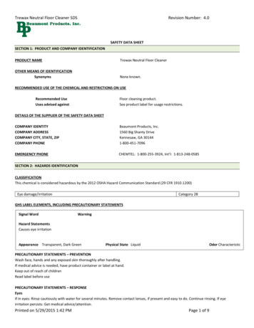
SECTION 2 PRE-INSTALLATION CONSIDERATIONS2.1EQUIPMENT LOCATIONThe MD302 SAM Standby Attitude Module is designed primarily to be installed in the instrumentpanel of the aircraft. However, within the limitations of the environmental qualifications, otherlocations may be acceptable when considered with the appropriate installation certification.The MD302 has an extra-wide viewing angle and AnyWayTM selectable orientation that allows forflexible installation locations and options. The unit can be mounted vertically (knob left or knob right)or horizontally (attitude left or attitude right). During configuration, the display orientation can beselected to match the desired installation. However, when selecting a location to install the MD302,be sure to consider appropriate field-of-view with regard to pilot and/or co-pilot visibility andaccessibility. Note: when installing in vertical orientation, choose the knob position based onwhether or not the pilot’s hand will obscure the display during operation. (Figure 2.1)Additionally, consider what equipment is behind the panel which may impede the installation of theMD302. Clearance for the unit as well as its electrical and pneumatic connections and routing mustbe allowed. Be aware of routing cables near other electronics or with other wire bundles that maybe susceptible to high energy flow. Avoid sharp bends in cabling or hoses and routing near aircraftcontrol cables. Also, avoid proximity and contact with aircraft structures, avionics equipment, heatsources or other obstructions that could chafe or damage wires or hoses during flight and causeundesirable effects.Manual Number 9017782Revision P, January 6, 20228
-90 directionof flightstraight andlevel flighttop view 90 side viewPanel tilt: -90 to 90 (horizontal shown; also applicable for vertical)MUST BE INSTALLED IN THE DIRECTION OFFLIGHTVERTICAL, KNOB LEFTVERTICAL, KNOB RIGHTHORIZONTAL, ATTITUDE LEFTHORIZONTAL, ATTITUDE RIGHTFIGURE 2.1INSTALLATION ORIENTATION OPTIONSManual Number 9017782Revision P, January 6, 20229
2.2LIMITATIONSThe conditions and tests for TSO approval of this article are minimum performance standards.Those installing this article on or in a specific type or class of aircraft must determine that theaircraft installation conditions are within the TSO standards, specification of the article, anddeviations listed below. TSO articles must have separate approval for installation in an aircraft. Thearticle may be installed only according to 14 CFR Part 43 or the applicable airworthinessrequirements.There are some portions of the approved TSOs which represent outdated requirements or do notapply to the product. These items are highlighted below and have been submitted to and approvedby the FAA as deviations to the TSO certifications of the product. In the case of FAA TSO andEASA ETSO-C3e and C6e, the MD302 has been approved as an “incomplete TSO”. For C3eTheMD302 meets all TSO requirements for applicable functions (slip) but does not meet the displayrequirements for rate of turn. A note below describes further details regarding the temperaturerequirements of FAA TSO-C113a, but does not represent a deviation.Where applicable, the environmental qualification requirements and test procedures identified withinthe TSOs have been superseded by the procedures of RTCA/DO-160, Revision G.FAA TSO-C2d: Airspeed Instruments instrument is not labeled with “Airspeed” or “IAS”FAA TSO-C3e: Turn and Slip Instrument - (incomplete) instrument does not provide rate-of-turn displayFAA TSO-C4c: Bank and Pitch Instruments dielectric strength/insulation resistance does not apply due to electronic componentsbetween chassis and connector pinsFAA TSO-C6e: Direction Instrument, Magnetic (Gyroscopically Stabilized) – (incomplete) instrument meets requirements for displaying heading requires external source to provide heading dataFAA TSO-C10b: Altimeter, Pressure Actuated, Sensitive Type instrument is not labeled with “Altitude” or “ALT” graduation increments are every 25 feet instead of 20 feet altimeter accuracy may be reduced when operating below -30 C (contact manufacturerfor additional information)FAA TSO-C113a: Airborne Multipurpose Electronic Displays For units prior to MOD 2, the display is operable but marginally usable at -30 C. Displayis fully functional at temperatures higher than -30 C. units incorporating MOD 2 have a built-in heater to provide full display visibility within 5minutes of applying power at -45 CManual Number 9017782Revision P, January 6, 202210
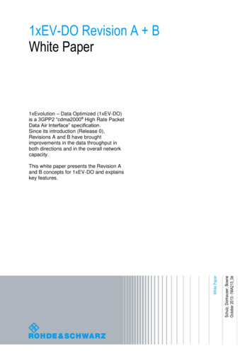
2.3MODIFICATIONThis product has a nameplate that identifies the manufacturer, part number, description,certification(s) and technical specifications of the unit. It also includes the “MOD” or modificationnumber representing notable changes in the hardware design of the unit.Modification (MOD) 0 is the initial release of the product and is identified on the nameplate by thelack of marking on the MOD numbers 1 through 9 (i.e. 1-9 are visible). All subsequent modificationsare identified on the nameplate by the marking/blacking out of that particular MOD number (i.e. forMOD 1, the number 1 is not visible and 2-9 are visible - see Figure 2.2 for examples). MODs do nothave to be sequentially inclusive and may be applied independent of each other.For additional details regarding specific changes associated with each MOD status refer to theproduct published Service Bulletins at www.mcico.com or www.flysam.com.MOD 0MOD 1MOD 1& MOD 2Figure 2.2Nameplate and MOD Status ExampleManual Number 9017782Revision P, January 6, 202211
SECTION 3 INSTALLATION3.1GENERAL INFORMATIONThis section contains interconnect diagrams, mounting dimensions and other information pertainingto the installation of the MD302 SAM Standby Attitude Module. After installation of cabling andbefore installation of the equipment, ensure that power is applied only to the pins specified in theinterconnect diagram.3.2PARTS LISTWhen unpacking this equipment, make a visual inspection for evidence of any damage that mayhave incurred during shipment. The following parts should be included:Item DescriptionMCIA Part Numbera. MD302 SAM Standby Attitude Modulei.Internal/Replacement Battery Pack(Installed on select versions)ii.Included/Replacement O-ringsb. Installation Manualc. Connector Kiti.Nutplateii.Pneumatic Connector (x2)iii.Screw, Hex, 6-32x5/8 (x4)iv.Screw, Flat, 2-56x1/4 (x2)v.Configuration Module1. 15-pin D-Sub2. Backshell3. Backshell Cover4. Printed Circuit Board Assembly5. Screw, Flat, 2-56x1/4(x2)6. Screw, 4-40x3/16(x4)7. Screw, 2-56x3-16(x2)3.36420302-( )9017177 (Type 1)9019120 (Type 190-208-100119017275CABLE HARNESSConstruct the cable harness in accordance with the instructions below including the ConnectorPinout of Table 3.1 and Figure 3.1 and Configuration Module Assembly of Figure 3.2. Installersshould follow industry-accepted practices regarding aircraft wiring and applicable regulatoryrequirements and guidance. The instructions for constructing the cable harness as listed within thismanual were also used to construct the harness during environmental and electrical testing.Alterations may invalidate environmental qualification and/or performance results.Refer to Section 2.1: Equipment Location for routing precautions.Manual Number 9017782Revision P, January 6, 202212
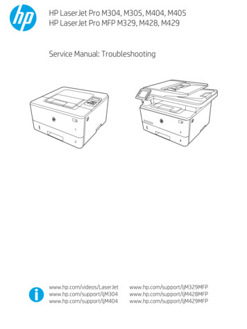
Wire Gauge SelectionWire gauge should be 22 AWG. Use of PTFE, ETFE, TFE, Teflon, or Tefzel insulated wire isrecommended for aircraft use per MIL-DTL-16878 or equivalent. Additionally, for data signalsassociated with ARINC 429 inputs and outputs, shielded twisted pair wiring per M27500 orequivalent is recommended (pin pairs 3 & 8 and 12 & 13).Configuration ModuleThe supplied custom configuration module is required for proper installation and operation of theunit. The functions associated with the 15-pin D-subminiature connector are identified as follows:Pin No.12345678Unit Connector Pin IdentificationDescriptionPin No. Description 10-32VDC Input9ARINC In #2 (A)Valid Signal Out10Config Module ClockARINC Out B11MD32 Power OutARINC In #2 (B)12ARINC In #1 (A)Config Module Power13ARINC In #1 (B)Power Return / Ground14Config Module DataLighting Bus Input15Config Module ReturnARINC Out ATABLE 3.1FIGURE 3.1VIEW FROM REAR OF MATING CONNECTORManual Number 9017782Revision P, January 6, 202213
To assemble the aircraft cable harness and Configuration Module refer to the following instructionsand Figure 3.2:1)Install a pin/socket as supplied in the Connector Kit using an appropriate crimpingtool for each wire in the aircraft cable harness. Be sure to make the harness longenough to remove the unit from the front of the panel without stressing the harness(approx. 8” longer than required to reach the unit connector).2)Braids from shielded wires should be separated from the wire conductors andpulled back from the pin/socket termination approximately 2” and gatheredtogether.i. NOTE: Additional chafe protection, such as heat shrink or nylon wire braid isrecommended over the bundle (not including the shields) to prevent wear wheninstalled in the cable clamp.3)Insert the pins of the cable harness into the rear of the 15-pin D-Sub connector (Item4) per Table 3.1 and Figure 3.1 using an appropriate pin insertion tool.CAUTIONCAUTION: The Configuration Module PC Board Assembly contains sensitiveelectronics that can be damaged by electrostatic discharge (ESD). Appropriateprecautions should be applied prior to handling this component.4)Insert the pins of the Configuration Module PC Board Assembly (Item 3) into theircorresponding locations as noted below using an appropriate pin insertion tool.a. The wires coming from the Configuration Module PC Board Assembly aremarked as follows on the circuit board: TP1, TP2, TP3, TP4.b. With the D-Sub oriented up (pin locations 1-5 on top), orient the ConfigurationModule PC Board Assembly with the electronic parts facing UP prior to pininsertion.c. Install each pin into the rear of the D-Sub connector as follows: Board TP1 config return D-Sub pin 15 Board TP2 config data D-Sub pin 14 Board TP3 config clock D-Sub pin 10 Board TP4 config power D-Sub pin 55)Install the D-Sub Backshell Spring (Item 5) as shown.6)Place the D-Sub Slide Lock (Item 6) over the D-Sub connector.7)Install the D-Sub connector with Slide Lock and cable harness attached into theBackshell (Item 1) and secure with (2) screws (Item 8). Verify that the BackshellSpring is between the Slide Lock and Backshell. Move the Slide Lock back andforth to verify free movement.8)Route the aircraft wire harness bundle (excluding shield braids) between the twohalves of the Cable Strain Relief Clamp (Item 7). The Clamp should be placed overthe chafe protection installed in Step 2 (if used).Manual Number 9017782Revision P, January 6, 202214
3.49)Loosely connect the two halves of the Cable Strain Relief Clamp with (2) screws(Item 8).10)Place the Cable Strain Relief Clamp in the Backshell as shown.11)Bend the wires of the Configuration Module PC Board Assembly 180 degrees sothat the PC Board has its electrical components facing down as shown. Be carefulnot to place excess strain on the solder connections between the wires and the PCBoard.12)Capture the Configuration Module PC Board Assembly into the Backshell byplacing the Backshell Cover (Item 2) on top of the Backshell.13)Secure the Backshell Cover onto the Backshell using (2) Screws (Item 9).14)Bundle the exposed shield braids and secure them to either threaded hole on therear of the Backshell using a 2-56 screw (Item 10). A wire that is common toaircraft chassis ground shall also be connected to one of these two holes on theBackshell. Use of a ring terminal (not included) may be useful.15)The completed assembly should look as shown. Verify that the Slide Lock operatesfreely and that no wires are pinched, nicked, or otherwise damaged.16)Verify that power and ground signals are installed appropriately before connectingto the unit.PITOT / STATIC CONNECTIONSThe connector kit supplied with the unit contains two (2) pneumatic quick disconnect fittings. Thesefittings are specific to the connections on the rear of the unit and required for proper operation.Aircraft tubing that connects to the unit must be ¼” OD with anapproximate 0.17” ID. When determining tubing length, be sure that itcan extend through the cutout in the panel by approximately 8” to allowthe unit to be installed and removed from the front of the panel.If o-rings are worn or damaged, replace with MCIA p/n 9017146 andinstall per the drawing as shown.MCIA p/n 9017146(x4)(rear of unit)CAUTIONNOTE: It is helpful to identify/label each tube (pitot or static) so that it can beconnected to the correct port on the back of the unit during installation.CAUTION: Lock quick disconnect before connecting to the unit to avoid damaging the O-ring.Manual Number 9017782Revision P, January 6, 202215
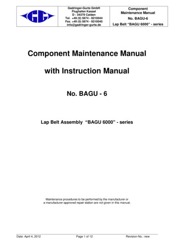
Item Qty Part Number 184-19016479part of 9016479part of 9016479part of 901647990-406-0001190-208-1001190-206-00011shield terminationFIGURE 3.2CONFIGURATION MODULE ASSEMBLYManual Number 9017782Revision P, January 6, 202216Backshell, Size 9Cover, BackshellPCB Assy, Config ModuleKit, DSub, 15pin HDDSub Backshell Spring ClipDSub Slide Lock, Size 9DSub Backshell Cable ClampScrew 4-40X3/16 Pan Phil Blk PatchScrew 2-56X1/4 Flat Phil Blk PatchScrew 2-56X3/16 Pan Phil Blk Patch
3.5MOUNTINGThe MD302 is designed primarily to be front mounted in an aircraft instrument panel. Refer toSection 2.1 for Equipment Location information. To install the unit in the instrument panel, follow theinstructions below and refer to Figures 3.3, 3.4 and 3.5.1) Once a location is selected, cut the panel per the dimensions in Figure 2.6. Other notes toconsider for panel cutout: (the Nutplate can be used as a basic template for the panelcutout) For vertical installation, rotate the panel cutout profile 90 . Be sure to leave space clear on the front of the panel for the bezel of the unit, which willextend significantly outside the main rectangular cutout. The dimension of the smaller side of the rectangle is critical for a good finished appearance.If it is too large, the cutout will be visible outside the unit bezel. The relationship of the holesto the cutout should be maintained closely to ensure proper installation. One countersink hole on either side of the rectangular cutout is required. Any of the threehole locations is acceptable. More than one countersink hole on each side is optional.Screws for these holes will retain the Nutplate and not support the weight of the unit. Verify that a flathead screw will sit flush or below the panel surface in the countersink holes.If not, deepen the countersinks slightly. Remove burrs around the cutout and holes to allow the unit to mount flush with the panel.2) Install the Nutplate on the backside of the instrument panel using at least one (1) flatheadscrew on each side of the rectangular cutout. The Nutplate should mount flush to the backside of the instrument panel. The threadednuts in corners of the Nutplate should protrude to the rear.3) Route the prepared cable harness and pitot/static fittings from behind the panel and throughthe panel cutout. The length of the cable harness should allow the unit to be connected infront of the panel.4) VERIFY THAT AIRCRAFT POWER IS TURNED OFF.5) Connect the cable harness with Configuration Module and pitot/static fittings to the rear ofthe unit.6) Insert the unit through the panel cutout and secure with four (4) hex head cap screwsprovided. Electrical bonding between the aircraft and the unit chassis is NOT required.3.6INSTALLATION COMPLETIONPrior to operating the unit in the aircraft, verify the basic operation of the unit and conduct astandard leak check of the pitot/static system per the aircraft maintenance manual or industrypractice. When initially powering the unit, an error may occur if a pre-configured unit is being matedto a Configuration Module for the first time or if the unit has yet to be configured. Acknowledge thiserror and either proceed to configuring the installation settings or cycle the power. The error shouldnot occur for subsequent startups.Manual Number 9017782Revision P, January 6, 202217
5.505.22.334.822.4" diagonalactive area2.37 2.094X Ø0.150 thru3.16Battery access2.30static port15-pin D-subpitot portUSB accessFIGURE 3.3MD302 OUTLINE DRAWINGPart 56420302-6**6420302-76420302-8Unit * Remote mounted unit version. Contact manufacturer for details.**Non-standard versionTABLE 3.2MD302 UNIT VERSIONSManual Number 9017782Revision P, January 6, 202218BatteryType 1NoneNoneType 1NoneNoneType 2Type 2
4X Ø.16 0.01 thruw Ø 0.175 X 82 countersinkonly 1 of 3 required per side4X R 0.10 max.295.7502.34 0.022.090.7503.25 0.05.295.50.505.220FIGURE 3.4PANEL CUTOUTSTEP 1STEP 2FIGURE 3.5INSTALL ILLUSTRATIONManual Number 9017782Revision P, January 6, 202219
SECTION 4 OPERATIONIMPORTANT: READ THIS ENTIRE SECTION PRIORTO STARTING INSTALLATION!The MD302 has four specific modes of operations: Pre-flight Mode - Section 4.2Flight Mode - Section 4.3Emergency Operation - Section 4.4Configuration Mode - Section 4.5This section contains information on how to use and interpret the information presented to the pilotand crew during normal and emergency operation of the MD302 SAM Standby Attitude Module.4.1USER INTERFACEThe MD302 SAM Standby Attitude Module is designed for simple, intuitive operation for ease of useand quick interpretation of the information displayed.The central control knob can be located at the bottom-center, middle-left or middle-right of the unitbezel depending on the installation orientation. This is the only user interface on the unit.The knob has two functions: push and turn. 4.2The knob provides 16-detents per revolution and typically increments whatever element itis controlling on the display one unit per detent.The push function is typically used to select the highlighted option in a menu and/or toenter and exit menus and control functions. The push function can also perform certainoperations with a push-and-hold action as described herein.PRE-FLIGHT MODEIn Pre-flight Mode, power is applied to the unit and the introduction screen appears during startup.(Figure 4.1) The startup screen will display the manufacturer’s logo, model name and number,SSEC identifier (if present), software version and total operating time.During Pre-flight Mode, the introduction screen will be displayed while the unit conducts an initialpower-up built-in test (PBIT) of the system to validate operational readiness. This includes, amongothers, a battery capacity measurement, an internal test to verify software and memory, and acheck that the internal settings and identification of the unit match the Configuration Moduleinstalled in the aircraft cable harness.Manual Number 9017782Revision P, January 6, 202220
The introduction screen will be displayed for approximately five seconds and will transition to FlightMode when complete.manufacturer’s logomodel name/numberSSEC File Version(if installed)software versiontotal operating timeFigure 4.1PRE-FLIGHT MODEManual Number 9017782Revision P, January 6, 202221
4.3FLIGHT MODEIn Flight Mode, the unit operates normally by displaying attitude, altitude, airspeed, heading(optional), and slip information. The Options Menu and brightness adjustment are also accessible inFlight Mode. (Figure 4.2)Figure 4.2FLIGHT MODEFunctionsWhile in Flight Mode, the MD302 provides up to five functions: attitude, altitude, airspeed,heading (optional), and slip indication. (Figure 4.2)Attitude OperationThe attitude indicator portion of the display can be configured on the right or left whenmounted horizontally and is always on the top display when oriented vertically. (Figure 2.1)The background of the display consists of the representative white horizon line separating the‘sky’ (blue) and ‘ground’ (brown).Manual Number 9017782Revision P, January 6, 202222
roll/bank scalepitch scalesymbolic airplanehorizon lineslip indicatorheading windowheading scaleFigure 4.3ATTITUDE OPERATIONThe roll scale is depicted as an arc of graduations representing bank angles of 0 (triangle),10, 20, 30, 45 (small triangle), and 60. The roll scale
Software Qualification: RTCA DO-178B, Design Assurance Level A Complex Hardware Qualification: RTCA DO-254, Design Assurance Level A Lithium-ion Qualification: UL 1642; RTCA DO-311; RTCA DO-347 (partial) Rights U.S. Patent No.: 9,739,611. Manual Number 9017782 Revision P, January 6, 2022 6 1.3 ARINC DATA LABELS All labels are defined as .