Transcription
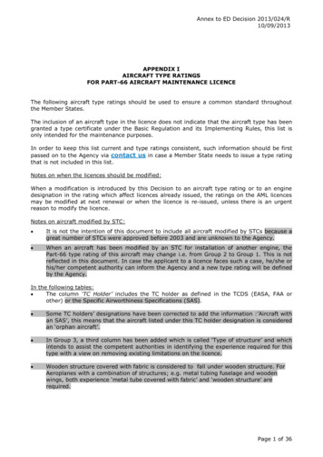
Cessna L19 Bird DogAircraft Operating InstructionsOPI – RCA Ops (Pac)Version 4.111 February 2011
RECORD OF REVISIONVersionNumberRevisionDateChange1.001 Jun 05Revision - Full IssueN/A2.001 Jun 06Limited RevisionN/A3.001 Jun 08Revision – Full IssueN/A4.026 Nov 10Revision – Full IssueN/A4.111 Feb 11Revision – Full IssueN/A1Amendments EnteredDateEntered By
NOTES TO USERSAUTHORITY1.This document is an official Canadian Forces Publication.2.This Aircraft Operating Instruction (AOI) is issued in compliance with theCanadian Forces Operational Airworthiness Manual, B-GA-104-000/FP-001. It is theauthoritative document for operation of the L19 Bird Dog within the Canadian Forces AirCadet Gliding Program (ACGP) in Pacific Region. It consolidates all relevant data andinformation including the following:a.all relevant data from the Pilot Operating Handbook (POH) for the modelyears in use;b.all placard data from Original Equipment Manufacturers (OEM);c.relevant data associated with the various Supplemental Type Certificatesfor modifications incorporated on the aircraft;d.relevant information from other OEM publications; ande.procedures and performance data unique to ACGP operations that havebeen validated through Operational Test and Evaluation (OT&E)conducted by Regional Cadet Air Operations (Pacific).APPLICABILITY2.These Aircraft Operating Instructions (AOI) and the associated Pilot’s Checklistpertain exclusively to Cessna L19 Bird Dog aircraft as modified for operation in the AirCadet Gliding Program in Pacific Region.IdentificationNumberTug 4Tug 5Tug 6Tug AAACYear ofManufacture19541953195219563.There are some configuration differences between the L19 “A” Model and L19”C”Model. Unless otherwise indicated, information provided is applicable to both Models.Any information unique to either Model is highlighted as such in this publication.2
STRUCTURE4.This AOI is divided into four Parts and one Annex:a.PART I – GENERAL DESCRIPTION – describes and illustrates thecontrols, systems and equipment with which the pilot should be familiar.b.PART II – NORMAL OPERATING PROCEDURES – describes the normalhandling of the aircraft by the pilot.c.PART III – EMERGENCY OPERATING PROCEDURES – details theemergency handling of the aircraft by the pilot.d.PART IV – OPERATING DATA AND LIMITATIONS – gives the flying andengine limitations and includes information on fuel consumption, range,and endurance under various conditions of flight.f.ANNEX A - PILOT’S GUIDE – GARMIN GNC-25-XL – OEM manual forGPS/COM radio5As a general rule, words written in capital letters throughout the text indicateactual markings on the controls concerned.REVISION PROCESS6.This publication is subject to annual review and revision. Comments andsuggestions for changes to this publication should be forwarded in writing to theRegional Cadet Air Operations Officer (Pacific).3
CAUTIONARY INFORMATION7.Where appropriate, cautionary information is provided. Such information will bepreceded by a highlighted header of Danger, Warning, Caution, or Note. Theseheaders are defined as follows:DANGERTo draw attention to a condition that poses an extreme,violent and continuous hazard to human life.WARNINGTo emphasize operating procedures, practices, etc, which, ifnot correctly followed, could result in personal injury or lossof life.CAUTIONTo emphasize operating procedures, practices, etc, which, ifnot correctly followed, could result in damage to ordestruction of equipment or legal claims or actions againstthe crown.NOTETo point out a procedure, event or practice which it isdesirable or essential to highlight.4
TABLE OF CONTENTSPART I – GENERAL DESCRIPTIONGENERAL.Aircraft Dimensions and Weights.Tank Capacities.101010AIRFRAME.General Layout Windows.Cabin Door.Pilot Seat .Rear Seat.Safety Belts and Harnesses.Baggage Compartment.1111151516161616FLIGHT CONTROLS.General .Control Columns .Rudder Pedals .Elevator Trim.Control Lock / Parking Brake .Wing Flaps.Wing Flap Position Indicator 1717171718181919LANDING GEAR.General .Tail Wheel Steering Brakes .Parking Brake.2020202020POWER UNIT.Engine.Propeller.Engine Controls .Throttle Control .Mixture Control .Air Induction and Carburettor Heat .Engine Cooling .Oil System.Ignition System.Exhaust System.21212121222222232324245
FUEL SYSTEM .General.Fuel Capacity .Fuel Specifications and Grade .Fuel Quantity Indicators .Fuel Selector Valve .Primer .Fuel Boost Pump .Fuel Pressure Gauge .Fuel Drain Valves .25252525252626262627ELECTRICAL SYSTEM.General .External Power .Battery Switch .Alternator .Starter .Circuit Breakers .Voltage Regulator .Digital Voltmeter / Ammeter .Alternator Warning Light .28282929292930303031LIGHTING SYSTEMS.Landing / Taxi Lights .Pulse Lights .Navigation Lights .Strobe Lights .Instrument Lighting .Map Light .32323232323232HEATING AND VENTILATION SYSTEM. 33General. 33Cabin Heat. 33Defrost and Pilot Heat. 33Cabin Ventilation . 33INSTRUMENTS. 34Pitot Static System. 34Vacuum System. 34Flight Instruments 35Engine Instruments . 36Stall Warning System. 37Clock . 37AVIONICS.Mic Buttons .Intercom System .GPS/COM.Transponder.ELT.6373737383940
MISCELLANEOUS EQUIPMENT.Glider Tow Hook.Tow Mirrors.Refuelling Steps .Tie Down Rings .Fuselage Lift Handles .Map Case .41414141414141SAFETY EQUIPMENT.Door Release Handle Fire Extinguisher.Life Preservers.First Aid Kit.Carbon Monoxide Detector.424242424242PART II – NORMAL OPERATING PROCEDURESGENERAL. 43PRE-FLIGHT/DAILY INSPECTION.Pre-External Inspection . . .External Inspection . . .Before Flight Inspection .43434447PRE-START CHECK. 48STARTING.Start.Pre-Taxi.Taxi.49495151GROUND OPERATIONS. 52RUN-UP. 54PRE-TAKEOFF. 55TAKEOFF.Normal Takeoff . . . . .Short Field Takeoff . . . .Soft / Rough Field Takeoff . . .Crosswind Takeoff . . . .Post Takeoff . . . .565657585859CLIMB PROFILES. 59CRUISE . 60Cruise Profiles . . . . . 60Level Off / Cruise . . . . . 607
FLIGHT MANOEUVRES / FLIGHT CHARACTERISTICS .Turns . . . . . .Slow Flight . . . . .Stalls . . . . . .Stall Recoveries .Spins . . . . .Spiral Dives . . . . .Side Slips . . . . . .6161616162626364PRE-STALL CHECK.64DESCENT . 64TRAFFIC PATTERN . 65FINAL APPROACH . 65LANDING .General . . . .Normal Landing . . . . . .Short Field Landing . . . . . .Soft / Rough Field Landing . . . .Crosswind Landing . . . . .Overshoot . . . . . .66666767686970CONTINUOUS CIRCUIT OPERATIONS . 71Touch and Go Landings . . 71Stop and Go Landings . . . 71POST LANDING CHECK . 72SHUTDOWN CHECK . 72MANAGEMENT OF ANCILLARY CONTROLS . 73Mixture Control . . . . . . 73Carburettor Heat . . . . . 73FUEL MANAGEMENT . 74GLIDER TOWING OPERATIONS. 76Aircraft Performance on Tow . . . . 76Prior to First Tow . . . . . 76Continuous Towing Operations . . . . 76Takeoff with Glider on Tow . . . . 77Glider Towing 77Glider Release . . . . .,,. . 78Descent After Release . . . . . 78Approach and Landing . ,,. . . . 78Cross Country Towing Operations . . . . 79SEVERE WEATHER OPERATIONS .Rain . . . . .Icing Conditions . . . . .Turbulence and Thunderstorms . . .80808080COLD WEATHER OPERATIONS. 818
PART III – EMERGENCY OPERATING PROCEDURESGENERAL.Priorities.Non-Critical Emergencies .Critical Emergencies .82828282NON-CRITICAL EMERGENCIES.Alternator Failure .Low Oil Pressure.Low Fuel Pressure .Split Flap .8383848485CRITICAL EMERGENCIES.Engine Fire on Start / on Ground.In-flight Fires.Engine Failures.Forced Landing/Ditching.8686878991PART IV – OPERATING DATA AND LIMITATIONSGENERAL. 92GENERAL SPECIFICATIONS.Weight Limitations.Engine Limitations.Airspeed Limitations.Normal Operating Airspeeds.Stall Speeds .Airspeed Correction Chart.92929294959596FLIGHT RESTRICTIONS. 97General . 97Flight Load Factors . 97PERFORMANCE DATA. 97Takeoff Speeds . 97Takeoff Distance . 98Climb Performance . 99Cruise Performance Data. 100Landing Speeds . 104Landing Distances . 105WEIGHT AND BALANCE. 106ANNEX A – PILOT’S GUIDE – GARMIN GNC-250XL9
PART IGENERAL DESCRIPTIONGENERAL1.The L19 is an all-metal, tandem, two-place high-wing monoplane. It wasdeveloped for the military as a multipurpose aircraft designed primarily forreconnaissance / observation. Its common military designation was L-19 “Birddog”,but it is also known by the military designator O-1 and by the civilian designatorCessna 305. Several variants of the aircraft were produced, and RCA Ops (Pac)operates the L19A and L19C model aircraft.2.This aircraft does not have a certified Pilot Operating Handbook (POH). This AOIincorporates OEM placard data, supplemental POH data associated with the variousSupplemental Type Certificates incorporated and additional relevant information fromCessna Company publications.Aircraft Dimensions and WeightsLength25 ft 9 ½ inWingspan36 ftHeight7 ft 6 inMaximum All Up Weight – L19 ”A”2300 lbsMaximum All Up Weight – L19 “C”2400 lbsBasic Empty WeightIAW Aircraft Weight and Balance RecordTable 1-1 Aircraft Dimensions and WeightsFuel Tank CapacitiesMain TankAuxiliary TankTotalTotal FuelUseable FuelLitresUS GalLitresUS 236.00Table 1-2 Fuel Tank CapacitiesOil CapacitiesQuarts / LitresMax Oil Capacity10 / 9.5Normal Oil Level8-9 / 7.6-8.5Minimum Oil Level8 / 8.5Table 1-3 Oil Capacity10
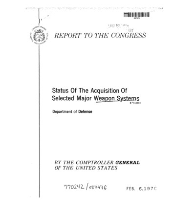
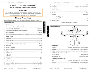
AIRFRAMEGeneral Layout3.Exterior and interior layout is detailed in Figures 1-1 through 1-4.Figure 1-1 General Arrangement11
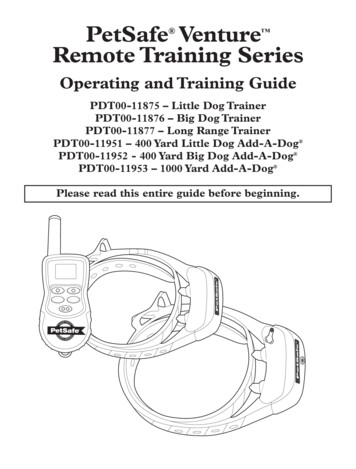
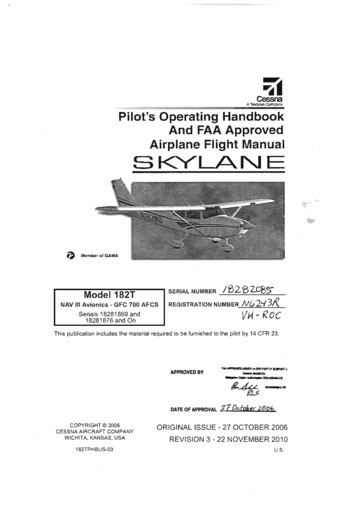
Figure 1-2 Cockpit Layout – Left Side1. Fuel Selector Valve2. Main Fuel Tank Gauge3. Tow Release Handle4. Map Light5. Fresh Air Vent6. Front Throttle Quadrant7 . Front Shoulder Harness Lock8. Elevator Trim Control Wheel9. Circuit Breaker Panel10. Rear Throttle Quadrant11. Rear Shoulder Harness Lock12. Rear Radio Transmit Switch13. Rear Flap Switch12
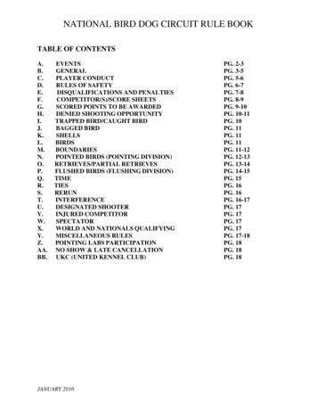
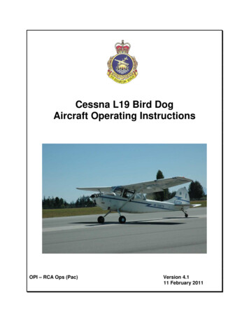
Figure 1-3 Cockpit Layout – Right Side1. Fresh Air Vent2. Deleted3. Auxiliary Fuel Tank Gauge4. Deleted5. Rear Control Column Storage6. Door/Window Handle7. Map Case8. Emergency Door Jettison Handle13
930Figure 1- 4 Cockpit Layout - Front1. Clock2. Air Speed Indicator3. Attitude Indicator4. Alternator Warning Light5. Altimeter6. Engine RPM7. Oil Temperature Gauge8. Oil Pressure Gauge9. Volt/Ammeter10. ELT Switch11. Fuel Pressure Gauge12. Suction Gauge13. Transponder14. Cylinder Head Temperature15. Fuel Boost Pump16. Battery Master Switch17. Alternator Switch18. Magneto Switch19. Starter Button20. Radio Master Switch21. Intercom Panel22. Directional Indicator23. Landing/Taxi Light Switch24. Engine Fuel Primer Switch25. Nav/Com Panel26. Turn and Slip Indicator27. Vertical Speed Indicator28. Rudder Pedals29. Fuel Pump30. Fire Extinguisher14
Windows4.In addition to the cabin door, there are two moveable windows in the cabin area.The window adjacent to the pilot on the left side of the aircraft is hinged at the top andopens out and up. To open this window, turn the handle counter-clockwise until thewindow swings free. A catch is mounted on the lower surface on the left wing forsecuring the window in the open position.5.The rear right window opens in and up. To open, turn the DZUS fasteners on thewindow frame a half-turn counter-clockwise. A canvas strap, which hangs from thecabin ceiling, holds this window open. The strap is fitted with a snap fastener, whichengages a snap fastener on the window. The left hand rear window is prevented fromopening by the tow release cable and wire bundles.WARNINGMaximum allowable airspeed with window(s) open is 120 MPH.NOTEUse only cleaner/polishing products certified for use onacrylic plastic to clean the windscreen or windows. Applywith micro fibre or flannel clothCabin Door6.The cabin door is mounted on the right side of the aircraft for entrance and exit.The door is composed of two sections. The upper section is a window, hinged on thetop edge that opens, up and out. The lower section is hinged along the forward edge.Handles are provided on both the inside and outside of the lower door section. To openthe window section of the door the handle is rotated down approximately 60 degreesuntil the window swings free. The window can be held open by engaging a catchlocated on the under surface of the wing. Rotate the handle further until the door isunlatched. The door will now swing forward until it contacts a stop located on the righthand wing strut.CAUTIONDo not slam the door to close it, as this can damage thelatching mechanism. The door is closed by smoothly andfirmly pulling it shut.15
Pilots Seat7.The pilot’s seat is mounted on two rails in the forward section of the cabin. Aseat adjustment lever is provided below the right side of the pilot’s seat. The pilot’s seatmay be adjusted fore or aft by raising the lever up, sliding the seat to the desiredposition, releasing the lever, and moving the seat fore and aft a short distance until theseat locking pins engage in the holes in the seat rails. The seat position shall beadjusted prior to engine start.WARNINGIf the seat retaining pins are not positively locked in position,the seat may suddenly move aft when power is appliedresulting in possible loss of aircraft control.Rear Seat8.The rear-seat backrest is removable and it can be installed in either the fore oraft position moving the pilot approximately four inches further forward or aft. It isnormally installed in the aft position.Safety Belts and Harnesses9.A safety belt and shoulder harness with associated locking mechanism mountedunder the floor aft of each seat is provided for both front and rear seats. A two-position(LOCKED and UNLOCKED) shoulder harness lock lever is located on the left cabin walladjacent to each seat. A latch is provided for positively retaining the lever at eitherposition of the quadrant. By pressing down on the top of the lever, the latch is releasedand the lever may be moved freely from one position to the other. The inertia reel willautomatically lock with the application of approximately 2-3g of forward acceleration.Baggage Compartment10.A baggage compartment is located behind the rear seat. Maximum weight limitfor this area is 100 lbs. The baggage compartment is accessible over the rear seatCAUTIONEnsure that any items stowed in the baggage compartmentare properly secured prior to flight.16
FLIGHT CONTROLSGeneral11.The aircraft is equipped with conventional flight controls that can be operatedfrom both the front and rear cockpit.Control Columns12.The elevator and aileron surfaces are operated by conventional movement ofeither one of the two control columns. The rear control column is removable by pullingout a control column release knob and lifting the control column from its socket. Twoclips for storage of the rear control column are mounted on the right rear window ledge.WARNINGThe rear control column must be removed for solo flight.When installing the rear control column, the slot at the baseof the control column must face aft, and ensure that thelocking pin is engaged.Rudder Pedals13.Two sets of rudder pedals are provided to mechanically operate the rudder andthe steerable tail wheel.14.The front pedals are located just aft of the firewall adjacent to the cabin floor andare equipped with brake-system master cylinders.15.The rear pedals are located just aft of the front seat and can be folded flat on thefloor by pulling up on the locking pin of each pedal and pushing the pedals down andaft. In this position, the pedals do not interfere with the normal operation of the frontrudder pedals. The pedals can be raised to the operating position by pulling them upand forward. Toe pressure on these pedals is mechanically transmitted to the frontpedals, which will, in turn, hydraulically actuate the main wheel brakes.WARNINGThe rear rudder pedals must be stowed for solo flight.WARNINGIf not properly secured by the locking pins the rear rudderpedals may fold when foot pressure is applied resulting inloss of rudder control from the rear seat.17
Elevator Trim16.An elevator trim-tab control wheel (Figure 1-2) is located on the left cabin wall.The tab control wheel is mechanically connected to the elevator tab by chains, cables,and a screw-jack actuator. A tab position indicator is incorporated to indicate the trimtab position. The indicator is labelled NOSE UP, NOSE DN, and TAKE OFF.Control Lock / Parking Brake17.A simple, positive control lock for rudder, elevators and ailerons is located on thecabin floor in front of the forward control column. The lock is a welded U shaped tubethat pivots inside the front rudder pedal torque tubes. The controls are locked andparking brakes are set simultaneously, by raising the U-tube and placing the locking pin,fixed to the front of the control column, into the hole on the underside of the tube. Tounlock the controls and release the parking brake, lift the tube from the locking pin andlower the tube to the cockpit floor.Figure 1- 5 Control Lock / Parking BrakeCAUTIONWhen parking the aircraft with control locks engaged for anextended period, ensure that the aircraft wheels arechocked. Reliance on the parking brake when the aircraft isunattended could result in aircraft movement in the unlikelyevent that brake pressure is lost.18
Wing Flaps18.Single-slotted, electrically actuated high-lift flaps extend from the fuselage to theaileron on each wing. Two separate wing-flap switches located in the front and rearcockpits control the flaps. The wing flaps can be moved electrically to any settingbetween 0 and 60 degrees, and locked in that position by releasing the switch andallowing it to return to OFF. When either the up or down flap limits are reached, the flapactuator motor is automatically turned off by limit switches.NOTEIn some circumstances where the flaps are selected DOWNto 10 degrees or less, the up limit switch may preventactivation of the flap motor when the flaps are subsequentlyselected UP. Should this occur, simply lower the flaps anadditional 5-10 degrees, and then re-select the flaps UP.19.The front cockpit has a three-position, spring-loaded wing flap switch mounted onthe window ledge adjacent to the engine control quadrant (Figure 1-6). The switchpositions are labelled FLAPS UP (forward) and FLAPS DOWN (aft). The centre positionof the switch is the OFF position.20.The rear cockpit switch is a four-position spring-loaded and guarded switchinstalled on the left hand side of the rear cockpit window ledge (Figure 1-2). When theswitch is moved from the NORMAL (down and guarded) position, to the OFF (unguardedand up) position, power to the flap selector switch in the front cockpit is cut off. The rearcockpit pilot is then able to adjust the flaps to the desired setting by moving the switch toeither the FLAPS UP or FLAPS DOWN position. The rear cockpit flap switch shouldremain in the NORMAL position when not in use.CAUTIONThe rear cockpit flap switch must be in the NORMALposition for solo flight.Wing Flap Position Indicator21.The position of the flaps can be ascertained by looking at the markings on therear cockpit window frame. There are witness marks at 10, 20, 30, 45, and 60 degreesand flaps can be selected at these settings or any setting in between.19
LANDING GEARGeneral22.The aircraft is equipped with a conventional landing gear system consisting of afixed main landing gear and a steerable tail wheel:a. the main landing gear incorporates a single tapered spring-steel leafsupporting each main wheel;b. the tail wheel is supported by a multi-leaf spring. The tail wheel steering armsare connected to the rudder by flexible cables and springs, and steering iscontrolled through normal operation of the rudder pedals; andc. tire inflation pressures are 21 psi (main wheels) and 35 psi (tail wheel).Tail Wheel Steering23.The tail wheel is steerable through an arc of 16 degrees each side of neutral.Beyond this travel the tail wheel becomes free swivelling.CAUTIONIf the tail wheel is allowed to turn through 16 degrees or more,the tail wheel unlocks and the tail will swing rapidly as themain wheels are ahead of the centre of gravity. Care shouldbe taken to avoid this condition developing into a ground loop.Brakes24.Hydraulic brakes on the main wheels are conventionally operated by applying toepressure to the top of either front or rear rudder pedals. The rotation of the pedalsactuates the hydraulic brake cylinders, resulting in a braking action on the main wheels.Parking Brake25.Engaging the control lock sets the parking brake (see Figure 1-5)20
POWER UNITEngine26.The aircraft power plant is a Teledyne-Continental O-470-11, six-cylinder,horizontally opposed, air-cooled engine with a pressure carburettor. At the maximumallowable engine speed of 2600 RPM, the engine is capable of developing 213 HP for amaximum of 5 minutes. Maximum continuous operation is limited to 2300 RPM wherethe engine is capable of generating 190 HP.Propeller27.The aircraft is normally equipped with a fixed-pitch McCauley two bladed, allmetal propeller 90 in. in diameter. A Hoffman four bladed, wooden propeller is alsocertified as an alternate configuration.CAUTIONWhen configured with the Hoffman propeller, Vne is reducedto 150 MPH. Care must also be taken to ensure that propellerspeed does not exceed 2600 RPM.NOTEThe Hoffman propeller does provide some reduction in noiselevels, but takeoff & climb performance are adversely affected.Engine Control
Cessna L19 Bird Dog Aircraft Operating Instructions OPI - RCA Ops (Pac) Version 4.1 11 February 2011 . 1 RECORD OF REVISION Version Amendments Entered Number Revision Date Change Date Entered By 1.0 01 Jun 05 Revision - Full Issue N/A 2.0 01 Jun 06 Limited Revision N/A 3.0 01 Jun 08 Revision - Full Issue .