Transcription
1xEV-DO Revision A BWhite Paper1xEvolution – Data Optimized (1xEV-DO)is a 3GPP2 “cdma2000 High Rate PacketData Air Interface” specification.Since its introduction (Release 0),Revisions A and B have broughtimprovements in the data throughput inboth directions and in the overall networkcapacity.Schulz, Donhauser, BowneOctober 2013 -1MA213 0eWhite PaperThis white paper presents the Revision Aand B concepts for 1xEV-DO and explainskey features.
Table of Contents1Introduction . 32Revision A. 52.1Overview of key features in Rev A.52.2Physical layer in Rev A .82.2.1Subtype 0 .82.2.2Subtype 1 .162.2.3Subtype 2 .173Revision B. 293.1Overview of key features in Rev B.293.2Physical layer in Rev B: Subtype 3 .323.2.1Multicarrier concept .323.2.2Forward link .363.2.3Reverse link .404Appendix . 474.11xEV-DO states .474.2Abbreviations.474.3References .484.4Additional Information .49CDMA2000 is a registered trademark of the Telecommunications IndustryAssociation (TIA -USA).
1 IntroductionWith the implementation of 1xEV-DO Release 0, 3GPP2 has developed the first mobileradio technology that is based completely on data traffic (packet-switched data, full IP).Channel widths (1.25 MHz), spectral characteristics and basic concepts were takenfrom CDMA2000 1X . The protocol is completely new and the forward link uses timedivision multiplexing (TDM).Release 0 permits data rates of up to 2.4 Mbps in the forward link. In the reverse linkdata rates of 153 kbps were possible. Release 0 was optimized for asymmetrical datatransfers that are tolerant of delays, such as web browsing or data downloads. Delaysensitive applications such as VoIP were not covered by Release 0.Revision A1xEV-DO Revision A was developed to enhance the forward and reverse data rates. Alarge number of changes were made in this transition.Early termination procedures were added to both the forward and reverse links, sothat the receiving side could acknowledge that a packet had been completely receivedprior to the end of the transmission of the packet. This allowed the link to benefit fromrapidly changing channel conditions.Other changes were made to improve the amount of time that it took to re-establish adata connection.More users were supported. Additional packet encoding formats, both smaller andlarger were added. The data rates on both the forward and reverse links improved asdid the end to end latency.1xEV-DO Revision A supports a maximum theoretical data rate of 3.1 Mbps in theforward link and 1.8 Mbps in the reverse link.The architecture of Revision A permits new services, including video telephony, voiceover IP (VoIP) and Push to Talk over Cellular (PoC).With Revision A different physical layer subtypes are defined. They are called Subtype0,1 and 2 (see section 2.2 for a detailed description).Revision BIn Revision B, data rates were further increased with the introduction of a higher modeof modulation in the forward link, as well as by aggregating multiple carriers(multicarrier mode).1xEV-DO Revision B supports multi-carrier operation where a number (up to 15) of1.25 MHz carriers may be used to create proportionally faster transmission speeds. Inthe real world, most implementations of 1xEV-DO Rev B, use 2 or 3 carriers. Additionalpacket encoding formats were defined to increase the maximum, per carrier, datarates to 4.9 Mbps on the forward link.With the addition of the new forward data rates and the multi-carrier operation, veryhigh speed data rates could be supported. Essentially, the forward link data rate could
be 'n' x 4.9 Mbps, with 'n' as the number of carriers. In the reverse link 'n' x 1.84 Mbpsare possible.With Revision B a new physical layer subtype 3 is defined (see section 3.2 for adetailed description).This white paper provides an overview of the essential characteristics of thetechnology behind 1xEV-DO Revisions A and B. 1xEV-DO Release 0 is described inmore detail where needed to better explain the optimizations or further developmentsin Revisions A and B. This white paper assumes a basic understanding of 1xEV-DORelease 0.
2 Revision A2.1 Overview of key features in Rev ARelease 0 was designed for asymmetrical usage; for example, web surfing, filedownloads and so on – tasks that primarily involve transferring data from the basestation to the end user (forward link) and that therefore are not overly impacted bydelays.The main intent of Rev A was to reduce the latency for applications such as voice(VoIP), PTT or gaming. The focus was also on increasing the data rate (e.g. forapplications like video telephony or video data transmission) both in the forward andthe reverse link.Revision A is fully backward compatible with Release 0. To ensure this, the physicallayer of Release 0 was implemented in Revision A as subtype 0. The communication inthe system always starts with the physical layer of Release 0 (or subtype 0).Based on the requirements described above, improvements and adaptations weremade in the physical layer that were then combined into subtype 2. A detaileddescription of the physical layer follows in 2.2.Improvements in the forward linkEarly terminationWhen implementing packet-switched transmission the possibility of early terminationby the base station during the transmission of data packets from the access terminal isdesirable. This would take place as soon as the data packet has been receivedcompletely and without errors. Before the data was transmitted, the MAC layer of theAT determined the class of transmission rate. The AN then choose, within this class,the data rate and repetition rate for the data packet to be transmitted, while taking theRF conditions between the AN and the AT into consideration. However, it is possiblefor the conditions to improve during the data transmission, which would make theoriginally selected higher repetition rate unnecessary. Allowing the receiver toterminate unneeded packet repetitions allows the next packet to be sent sooner.This is why an automatic retransmission request (ARQ) was implemented in theforward link, with the option of early termination.Data rates / packet sizesAdditional packet sizes were defined along with additional data rates. For delaysensitive services such as voice transmission (VoIP), small packet sizes wereintroduced that reduce the latency. This does not increase the data rate. On the otherhand, the introduction of large packet sizes allow higher data rates (up to 3.072 Mbps).
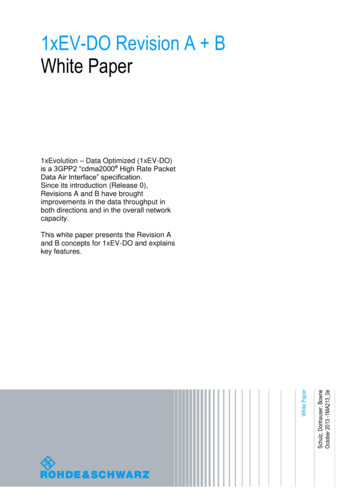
Multi-user packetsMulti-user packets were defined for the forward link. Multi-user packets can carry datafor multiple ATs. The AT is able to distinguish between a single-user packet and amulti-user packet via the protocol.Improvements in the reverse linkSubpacketsSubpackets and subframes were newly defined in order to support hybrid-ARQ modeon the reverse link.Fig. 1: Subpackets in reverse link subtype 2. A total of 26.66 ms is required to transmit a frame.In subtype 2, the reverse traffic channel uses an interleaved transmission. The ATsends these data packets split into up to four subpackets, which in turn are alwaystransmitted in four contiguous slots in interlaced mode.The subpackets are separated by two subframes that transmit data from other packets.This interlaced operation uses time-delayed transmission of contiguous data packets tocreate time for responses from the base station.Data rates / modulationNew packet sizes were defined that provide effective data rates from 4.8 kbps to1843.2 kbps. Higher modulation modes are also used (QPSK and 8-PSK).Soft handoffRelease 0 provided a soft handoff between cells. Although switching between cellsinterrupted the data transfer, it did not significantly affect applications such as websurfing or downloads. In Release 0 the Soft handoff is controlled via the DRC channel(see 2.2.1.2).To support delay-sensitive applications, a new channel was introduced (DSC; see2.2.3.2), which transmits the same information as the DRC, but is updated more often.
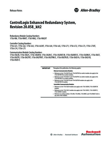
Protocol changesFig. 2: Overview of the protocol stack in Revision A.Rev A introduced the multiflow packet application in the application layer. This was animportant step to ensure that different applications (VoIP, gaming, etc.) can be activeat the same time.Special applications were additionally defined in [2] to support testing of the physicallayer. This ensures well defined parameter sets for repeatable testing. The forward testapplications allow testing of the AT’s receiver. The reverse test applications are forAT’s transmitter testing. For Revision A, these are Forward test application (FTAP): (Defined in Release 0)– Supports Subtype 0/1: DRCIndices 0 to 12: 0 bps to 2457.6 kbps (see Fig. 6) Reverse test application (RTAP): (Defined in Release 0)– Supports Subtype 0/1: Data rate indices 0 to 5: 0 bps to 153.6 kbps Forward enhanced test application (FETAP): (Defined in Rev A)– Supports Subtype 2: Packet type 1 to 37: 4.8 kbps to 3072.0 kbps (see Fig. 14to Fig. 17) Reverse enhanced test application (RETAP): (Defined in Rev A)– Supports Subtype 2: Data rate indices 0 to 12: 0 bps to 1843.2 kbps
Hybrid mode / Cooperation with CDMA2000To support voice and data services, an AT with hybrid mode can operate in both 1xEVDO and CDMA2000 networks and monitor the control channels of each network. Forthis it has to switch between both networks (if only one RF chain is assumed). Once anactive connection is needed, the AT must switch to that network. Unless the AT is ableto periodically tune away from the active network, there was no way to be active onboth networks at the same time.With Revision A a new protocol was defined, that allows CDMA messages to be sentthrough 1xEV-DO to enable calls, SMS and other network operations.2.2 Physical layer in Rev ARev A specifies three different physical layer subtypes: Subtype 0: Corresponds to the physical layer from Rel 0 and ensures full backwardcompatibilitySubtype 1: Incorporates small changes in the reverse link and no changes in theforward linkSubtype 2: Incorporates changes in both the forward and the reverse link, and istherefore the most important subtype in Rev A2.2.1 Subtype 0Physical layer subtype 0 corresponds to the physical layer in Release 0. As a result,Revision A is fully backward compatible with Release 0.2.2.1.1Forward linkFig. 3 provides an overview of the channels in the forward link.Fig. 3: Forward link channel structure (subtype 0).
Fig. 4: Overview of the channel structure in the forward link (subtype 0). All channels are timemultiplexed and provided with different Walsh covers. The MAC channel uses CDM using theMACindex to select active AT’s.All channels in the forward link are transmitted by the use of time-division multiplexing(TDM).Code-division multiplexing (CDM) is only used in the MAC. A frame is 26.67 mslong and consists of 16 slots. A slot is therefore 1.67 ms long and is further split intotwo half slots, each with a duration of 833.3 µs.Fig. 5: Slot structure in the forward link. In principle, every half slot always transmits the MAC andthe pilot (idle slot). If data is also to be transmitted (active slot), then two data packets aretransmitted in every half slot.Pilot channelThe access network continually broadcasts the pilot channel in every half slot at fullpower. This provides a reference signal for coherent demodulation of the data and
MAC channels. It is also used to synchronize all access terminals in the sector. Theaccess terminals detect the available pilot signals from various sectors and select thestrongest. The pilot signal is not modulated (All 0) and is transmitted only using theI component.MAC channelsThe MAC channels consist of three subchannels that are divided by means of codedivision multiplexing (CDM). For this purpose, they each use one of 64 Walsh codes (0to 63). Even Walsh codes (known as MACIndices) are sent on the I component andodd Walsh codes on the Q component. Only 1 bit is transmitted using BPSKmodulation.MAC subchannel: Reverse activity (RA)The access network uses the RA bit (RAB) to inform access terminals that it shoulddecrease its data rate in the reverse link. This is done to reduce the load of the basestation in times of heavy reverse link activity. The RAB channel uses MACIndex(Walsh code) 4 and is transmitted on the I component. The update rate is adjustablebetween 8 and 64 slots. All AT’s with an active connection must monitor this bit. Whenthe bit becomes active the AT will pseudo-randomly decide if they should lower theirreve
White Paper 1xEvolution – Data Optimized (1xEV-DO) . The architecture of Revision A permits new services, including video telephony, voice over IP (VoIP) and Push to Talk over Cellular (PoC). With Revision A different physical layer subtypes are defined. They are called Subtype 0,1 and 2 (see section 2.2 for a detailed description). Revision B In Revision B, data rates were further .


![First Revision No. 147-NFPA 20-2013 [ Global Input ]](/img/4/20-a15-fim-aaa-fd-frstatements.jpg)
![First Revision No. 2-NFPA 33-2016 [ Section No. 1.3 ]](/img/4/33-f2017-faa-aaa-frreport.jpg)
