Transcription
GE Oil & GasHigh speed reciprocating compressorsH301 and 302 series operating manual
Document Revision Chart 2012 General Electric CompanyAll Rights ReservedThe following chart lists the revisions made to this document tracked by version.RevisionRevision descriptionDateAuthorApprover2.0Updated safety information and madedocument usable online3/9/2012Luette A.Jim H.2.1Added piston head end and crankend clearance7/10/12Luette A.Jim H.2.2Update parts phone number, efax,website, rearrange connecting rodform7/25/13Luette A.Jim H.
ContentsAcronyms . . . . . . . . . . . . . . . . . . . . . . . . . . . . . . . . . . . . . . . . . . . . . . . . . . . . . . . . . . . . . .Lisf of Figures . . . . . . . . . . . . . . . . . . . . . . . . . . . . . . . . . . . . . . . . . . . . . . . . . . . . . . . . . .List of Forms . . . . . . . . . . . . . . . . . . . . . . . . . . . . . . . . . . . . . . . . . . . . . . . . . . . . . . . . . . VList of Tables. . . . . . . . . . . . . . . . . . . . . . . . . . . . . . . . . . . . . . . . . . . . . . . . . . . . . . . . . . . VIChapter 1: Getting Started. . . . . . . . . . . . . . . . . . . . . . . . . . . . . . . 1Customer Service. . . . . . . . . . . . . . . . . . . . . . . . . . . . . . . . . . . . . . . . . . . . . . . . . . . . . . 1Documentation. . . . . . . . . . . . . . . . . . . . . . . . . . . . . . . . . . . . . . . . . . . . . . . . . . . . . . . . 1Request Access to the Website. . . . . . . . . . . . . . . . . . . . . . . . . . . . . . . . . . . . . 1Compressor News Bulletins . . . . . . . . . . . . . . . . . . . . . . . . . . . . . . . . . . . . . . . . 1Operating Manuals. . . . . . . . . . . . . . . . . . . . . . . . . . . . . . . . . . . . . . . . . . . . . . . . 1Give Feedback. . . . . . . . . . . . . . . . . . . . . . . . . . . . . . . . . . . . . . . . . . . . . . . . . . . . . 1Parts. . . . . . . . . . . . . . . . . . . . . . . . . . . . . . . . . . . . . . . . . . . . . . . . . . . . . . . . . . . . . . . . . . 2Safety Advisories. . . . . . . . . . . . . . . . . . . . . . . . . . . . . . . . . . . . . . . . . . . . . . . . . . . . . . . 2Types of Safety Advisories. . . . . . . . . . . . . . . . . . . . . . . . . . . . . . . . . . . . . . . . . . 2Safety Symbols. . . . . . . . . . . . . . . . . . . . . . . . . . . . . . . . . . . . . . . . . . . . . . . . . . . . 5Technical Support. . . . . . . . . . . . . . . . . . . . . . . . . . . . . . . . . . . . . . . . . . . . . . . . . . . . . . 6Training . . . . . . . . . . . . . . . . . . . . . . . . . . . . . . . . . . . . . . . . . . . . . . . . . . . . . . . . . . . . . . . 6Warranty. . . . . . . . . . . . . . . . . . . . . . . . . . . . . . . . . . . . . . . . . . . . . . . . . . . . . . . . . . . . . . 6Chapter 2: Introduction. . . . . . . . . . . . . . . . . . . . . . . . . . . . . . . . . . 9H 301/302 Series Frame/Running Gear Assembly . . . . . . . . . . . . . . . . . . . . . . . 9H 30 Series Cylinder Assembly for H Series frames. . . . . . . . . . . . . . . . . . . . . . . 9Commissioning Report. . . . . . . . . . . . . . . . . . . . . . . . . . . . . . . . . . . . . . . . . . . . . . . . 10Components of the H 301/302 Series . . . . . . . . . . . . . . . . . . . . . . . . . . . . . . . . . . 10High Speed Reciprocating Compressor – Startup Report. . . . . . . . . . . . . . . . 11Startup Report. . . . . . . . . . . . . . . . . . . . . . . . . . . . . . . . . . . . . . . . . . . . . . . . . . . . 11Pre-Startup Checklist . . . . . . . . . . . . . . . . . . . . . . . . . . . . . . . . . . . . . . . . . . . . . 14Post-Startup Checklist . . . . . . . . . . . . . . . . . . . . . . . . . . . . . . . . . . . . . . . . . . . . 17Gas Compressor Record. . . . . . . . . . . . . . . . . . . . . . . . . . . . . . . . . . . . . . . . . . . . . . . 18Crankshaft Rotation. . . . . . . . . . . . . . . . . . . . . . . . . . . . . . . . . . . . . . . . . . . . . . . . . . . 19Chapter 3: General Data/Specifications. . . . . . . . . . . . . . . . . . 21Frame Specifications . . . . . . . . . . . . . . . . . . . . . . . . . . . . . . . . . . . . . . . . . . . . . . . . .Bearings and Running Gear. . . . . . . . . . . . . . . . . . . . . . . . . . . . . . . . . . . . . . . . . . .Lubrication System . . . . . . . . . . . . . . . . . . . . . . . . . . . . . . . . . . . . . . . . . . . . . . . . . . .Cylinder Nameplates. . . . . . . . . . . . . . . . . . . . . . . . . . . . . . . . . . . . . . . . . . . . . . . . . .Piston Head End and Crank End Clearance. . . . . . . . . . . . . . . . . . . . . . . . . . . . .Cylinder Sizes, Bores, Piston Diameters, Clearance and Weight. . . . . . . . . .Piston Ring and Packing Ring Clearances . . . . . . . . . . . . . . . . . . . . . . . . . . . . . .Fastener Torque Values. . . . . . . . . . . . . . . . . . . . . . . . . . . . . . . . . . . . . . . . . . . . . . .Fastener Torquing . . . . . . . . . . . . . . . . . . . . . . . . . . . . . . . . . . . . . . . . . . . . . . . . . . . .Hold Down Bolting. . . . . . . . . . . . . . . . . . . . . . . . . . . . . . . . . . . . . . . . . . . . . . . . . . . .Balance Weights . . . . . . . . . . . . . . . . . . . . . . . . . . . . . . . . . . . . . . . . . . . . . . . . . . . . .2122242425252727283030H301/302 HSR Compressors Rev. 2.2 I
Chapter 4: Installation. . . . . . . . . . . . . . . . . . . . . . . . . . . . . . . . . . 39Access and Safety . . . . . . . . . . . . . . . . . . . . . . . . . . . . . . . . . . . . . . . . . . . . . . . . . . . .Vents and Drains. . . . . . . . . . . . . . . . . . . . . . . . . . . . . . . . . . . . . . . . . . . . . . . . . . . . .Secure the Skid and Foundation (Sub-Base) . . . . . . . . . . . . . . . . . . . . . . . . . . . .Skid Leveling and Alignment . . . . . . . . . . . . . . . . . . . . . . . . . . . . . . . . . . . . . . . . . .Compressor Frame Leveling. . . . . . . . . . . . . . . . . . . . . . . . . . . . . . . . . . . . . . .Alignment. . . . . . . . . . . . . . . . . . . . . . . . . . . . . . . . . . . . . . . . . . . . . . . . . . . . . . . .Maximum Allowable Drive Train Misalignment . . . . . . . . . . . . . . . . . . . .Driver to Compressor Free Coupling Alignment . . . . . . . . . . . . . . . . . . . .Compressor Crankshaft End Thrust Clearance . . . . . . . . . . . . . . . . . . . . .Skid Hold-Down Bolting. . . . . . . . . . . . . . . . . . . . . . . . . . . . . . . . . . . . . . . . . . . . . . .Recommended Bolt Size/Torque . . . . . . . . . . . . . . . . . . . . . . . . . . . . . . . . . .Bolting Requirements . . . . . . . . . . . . . . . . . . . . . . . . . . . . . . . . . . . . . . . . . . . .Bolt/Fastener Tightening . . . . . . . . . . . . . . . . . . . . . . . . . . . . . . . . . . . . . . . . .Piping. . . . . . . . . . . . . . . . . . . . . . . . . . . . . . . . . . . . . . . . . . . . . . . . . . . . . . . . . . . . . . . .Process Gas Piping. . . . . . . . . . . . . . . . . . . . . . . . . . . . . . . . . . . . . . . . . . . . . . . .Lubricating Oil Piping and Tubing. . . . . . . . . . . . . . . . . . . . . . . . . . . . . . . . . .Compressor Valves . . . . . . . . . . . . . . . . . . . . . . . . . . . . . . . . . . . . . . . . . . . . . . . . . . .3939404141424444454646474748484950Chapter 5: Operation. . . . . . . . . . . . . . . . . . . . . . . . . . . . . . . . . . . 53Maximum Allowable Working Pressure (MAWP) . . . . . . . . . . . . . . . . . . . . . . . . 54Rated Discharge Pressure. . . . . . . . . . . . . . . . . . . . . . . . . . . . . . . . . . . . . . . . . . . . . 54Cylinder Discharge Temperature Shutdown Settings . . . . . . . . . . . . . . . . . . .Shut Down Setting Recommendations . . . . . . . . . . . . . . . . . . . . . . . . . . . .Discharge Temperature Calculations . . . . . . . . . . . . . . . . . . . . . . . . . . . . . .Cylinder Temperature Shutdown Setting/Formula. . . . . . . . . . . . . . . . . .Compressor Relocation or Reapplication. . . . . . . . . . . . . . . . . . . . . . . . . . . . . . .Compressor Frame and Cylinder Information. . . . . . . . . . . . . . . . . . . . . . . . . . .Filling Crankcase Sump . . . . . . . . . . . . . . . . . . . . . . . . . . . . . . . . . . . . . . . . . . .Pre Lube Frame . . . . . . . . . . . . . . . . . . . . . . . . . . . . . . . . . . . . . . . . . . . . . . . . . .Crankcase Oil Level. . . . . . . . . . . . . . . . . . . . . . . . . . . . . . . . . . . . . . . . . . . . . . .Cylinder Lubricator System Priming . . . . . . . . . . . . . . . . . . . . . . . . . . . . . . .Compressor Reapplication or Relocation Checklist . . . . . . . . . . . . . . . . .Initial No-Load Rotational Test Run. . . . . . . . . . . . . . . . . . . . . . . . . . . . . . . .Initial Load Run. . . . . . . . . . . . . . . . . . . . . . . . . . . . . . . . . . . . . . . . . . . . . . . . . . .Operate the Compressor. . . . . . . . . . . . . . . . . . . . . . . . . . . . . . . . . . . . . . . . . . . . . .Start the Compressor. . . . . . . . . . . . . . . . . . . . . . . . . . . . . . . . . . . . . . . . . . . . .Stop the Compressor . . . . . . . . . . . . . . . . . . . . . . . . . . . . . . . . . . . . . . . . . . . . .55555555565757575858586062626465Chapter 6: Lubrication. . . . . . . . . . . . . . . . . . . . . . . . . . . . . . . . . . 67Frame And Running Gear Lubrication. . . . . . . . . . . . . . . . . . . . . . . . . . . . . . . . . .Pressure Regulating Valves (PRV). . . . . . . . . . . . . . . . . . . . . . . . . . . . . . . . . . . . . .Disassemble the PRV . . . . . . . . . . . . . . . . . . . . . . . . . . . . . . . . . . . . . . . . . . . . .Inspect the PRV . . . . . . . . . . . . . . . . . . . . . . . . . . . . . . . . . . . . . . . . . . . . . . . . . .Re-assemble the PRV. . . . . . . . . . . . . . . . . . . . . . . . . . . . . . . . . . . . . . . . . . . . .Crankcase Lubricant Selection . . . . . . . . . . . . . . . . . . . . . . . . . . . . . . . . . . . .II H301/302 HSR Compressors Rev. 2.1676972727273
Oil Viscosity . . . . . . . . . . . . . . . . . . . . . . . . . . . . . . . . . . . . . . . . . . . . . . . . . . . . . .Non-Lube Cylinder Applications . . . . . . . . . . . . . . . . . . . . . . . . . . . . . . . . . . . . . . .Cylinder Lubrication System. . . . . . . . . . . . . . . . . . . . . . . . . . . . . . . . . . . . . . . . . . .System Installation . . . . . . . . . . . . . . . . . . . . . . . . . . . . . . . . . . . . . . . . . . . . . . .Entrapped Air Removal . . . . . . . . . . . . . . . . . . . . . . . . . . . . . . . . . . . . . . . . . . .Setup and Adjust Lubricator Pump . . . . . . . . . . . . . . . . . . . . . . . . . . . . . . . . . . . .New Compressor Start-Up . . . . . . . . . . . . . . . . . . . . . . . . . . . . . . . . . . . . . . . .Cylinder Wall Oil Film Wipe Test . . . . . . . . . . . . . . . . . . . . . . . . . . . . . . . . . . .Guideline for Oil Film Wipe Test Results . . . . . . . . . . . . . . . . . . . . . . . . . . . .Cylinder Lubrication Flow Rate and Cycle Indicator . . . . . . . . . . . . . . . .Rupture Disks. . . . . . . . . . . . . . . . . . . . . . . . . . . . . . . . . . . . . . . . . . . . . . . . . . . . .Digital Cylinder Lube No-Flow Devices. . . . . . . . . . . . . . . . . . . . . . . . . . . . .Install Kenco NFS-3 No-Flow Switch. . . . . . . . . . . . . . . . . . . . . . . . . . . . . . .73747475757677787879808283Chapter 7: Vibration. . . . . . . . . . . . . . . . . . . . . . . . . . . . . . . . . . . . 89Types of Vibration. . . . . . . . . . . . . . . . . . . . . . . . . . . . . . . . . . . . . . . . . . . . . . . . . . . . .Mechanical . . . . . . . . . . . . . . . . . . . . . . . . . . . . . . . . . . . . . . . . . . . . . . . . . . . . . . . . . .Inertia Unbalance . . . . . . . . . . . . . . . . . . . . . . . . . . . . . . . . . . . . . . . . . . . . . . . . . . . .Pressure Pulsations . . . . . . . . . . . . . . . . . . . . . . . . . . . . . . . . . . . . . . . . . . . . . . . . . . .Torsional Vibration . . . . . . . . . . . . . . . . . . . . . . . . . . . . . . . . . . . . . . . . . . . . . . . . . . .Vibration Amplitude versus Frequency . . . . . . . . . . . . . . . . . . . . . . . . . . . . . . . .899090919192Chapter 8: Maintenance. . . . . . . . . . . . . . . . . . . . . . . . . . . . . . . . 95Component Weights. . . . . . . . . . . . . . . . . . . . . . . . . . . . . . . . . . . . . . . . . . . . . . . . . . 96Frame and Frame Components . . . . . . . . . . . . . . . . . . . . . . . . . . . . . . . . . . . 96Preventive Maintenance . . . . . . . . . . . . . . . . . . . . . . . . . . . . . . . . . . . . . . . . . . 97Record Keeping . . . . . . . . . . . . . . . . . . . . . . . . . . . . . . . . . . . . . . . . . . . . . . . . . . 97Oil Analysis. . . . . . . . . . . . . . . . . . . . . . . . . . . . . . . . . . . . . . . . . . . . . . . . . . . . . . . 97Cleanliness. . . . . . . . . . . . . . . . . . . . . . . . . . . . . . . . . . . . . . . . . . . . . . . . . . . . . . . 97Inspect Gaskets and O-rings . . . . . . . . . . . . . . . . . . . . . . . . . . . . . . . . . . . . . . 97Recommended Maintenance . . . . . . . . . . . . . . . . . . . . . . . . . . . . . . . . . . . . . 98Daily Maintenance Checklist. . . . . . . . . . . . . . . . . . . . . . . . . . . . . . . . . . . . . . 98Monthly Maintenance Checklist . . . . . . . . . . . . . . . . . . . . . . . . . . . . . . . . . . . 99Quarterly Maintenance Checklist. . . . . . . . . . . . . . . . . . . . . . . . . . . . . . . . . 100Semi-Annual Maintenance Checklist. . . . . . . . . . . . . . . . . . . . . . . . . . . . . . 100Annual Maintenance Checklist . . . . . . . . . . . . . . . . . . . . . . . . . . . . . . . . . . . 101Optional VVCP Assembly Capacity Control . . . . . . . . . . . . . . . . . . . . . . . . 101Adjust the Variable Volume Clearance Pocket (VVCP) Assembly. . . . . 102Connecting Rod Inspection Sheet – H Frame. . . . . . . . . . . . . . . . . . . . . . . . . . 109Chapter 9: Troubleshooting . . . . . . . . . . . . . . . . . . . . . . . . . . . 111Appendix A: H Series Tools. . . . . . . . . . . . . . . . . . . . . . . . . . . . . A-1Index. . . . . . . . . . . . . . . . . . . . . . . . . . . . . . . . . . . . . . . . . . . . . . . . . B-2H301/302 HSR Compressors Rev. 2.2 III
AcronymsPRV - Pressure regulating valveVVCP - Variable voulme clearance pocketIV H301/302 HSR Compressors Rev. 2.1
List of ureFigureFigureFigureFigureFigureFigure1 Safety symbols. . . . . . . . . . . . . . . . . . . . . . . . . . . . . . . . . . . . . . . . . . . . . . . . . . . . 52 H 301/302 H Series compressor components . . . . . . . . . . . . . . . . . . . . . . 103 Crankshaft rotation. . . . . . . . . . . . . . . . . . . . . . . . . . . . . . . . . . . . . . . . . . . . . . . 194 Cylinder nameplate. . . . . . . . . . . . . . . . . . . . . . . . . . . . . . . . . . . . . . . . . . . . . . . 245 Torque wrench with adapter at any angle except 90 right angle. . . . 296 Torque wrench with adapter at right angle (90 ). . . . . . . . . . . . . . . . . . . . 297 Maximum out of balance weight of opposing throws. . . . . . . . . . . . . . . 308 Sketch description of misalignment . . . . . . . . . . . . . . . . . . . . . . . . . . . . . . . 439 Dial indicator arrangement. . . . . . . . . . . . . . . . . . . . . . . . . . . . . . . . . . . . . . . . 4310 Inlet strainer. . . . . . . . . . . . . . . . . . . . . . . . . . . . . . . . . . . . . . . . . . . . . . . . . . . . 4911 Piping schematic. . . . . . . . . . . . . . . . . . . . . . . . . . . . . . . . . . . . . . 6312 Frame and running gear lubrication system. . . . . . . . . . . . . . . . . . . . . . 6713 GE oil filter standard 1-105292. . . . . . . . . . . . . . . . . . . . . . . . . . . . . . . . . . . 6914 PRV assembled and exploded parts illustration. . . . . . . . . . . . . . . . . . . 7215 Typical lubricator pump with plunger shown at max stroke/flow. . . 7716 Rupture assembly . . . . . . . . . . . . . . . . . . . . . . . . . . . . . . . . . . . . . . . . . . . . . . 8117 Kenco NFS-3 No-Flow Switch. . . . . . . . . . . . . . . . . . . . . . . . . . . . . . . . . . . . 8318 DNFT-LED Switch Assembly, with magnetic housing assembly. . . . . 8519 Vibration amplitude versus frequency chart. . . . . . . . . . . . . . . . . . . . . . 9220 Typical variable volume clearance pocket installed. . . . . . . . . . . . . . 10221 Effective rod extension: amount pocket is open. . . . . . . . . . . . . . . . . . 10422 VVCP flange lubrication fitting and threads. . . . . . . . . . . . . . . . . . . . . . 107H301/302 HSR Compressors Rev. 2.2 V
List of ormFormFormVI H301/302 HSR Compressors Rev. 2.11 Startup report. . . . . . . . . . . . . . . . . . . . . . . . . . . . . . . . . . . . . . . . . . . . . . . . . . . . . . 132 Pre-startup checklist. . . . . . . . . . . . . . . . . . . . . . . . . . . . . . . . . . . . . . . . . . . . . . . . 163 Post-Startup checklist. . . . . . . . . . . . . . . . . . . . . . . . . . . . . . . . . . . . . . . . . . . . . . . 174 Gas compressor record. . . . . . . . . . . . . . . . . . . . . . . . . . . . . . . . . . . . . . . . . . . . . 185 Compressor frame and cylinder data tag information. . . . . . . . . . . . . . . . 576 Reapplication or relocation checklist. . . . . . . . . . . . . . . . . . . . . . . . . . . . . . . . . 597 Initial no-load rotational test run checklist . . . . . . . . . . . . . . . . . . . . . . . . . . . 618 Initial load run checklist. . . . . . . . . . . . . . . . . . . . . . . . . . . . . . . . . . . . . . . . . . . . . 629 Daily maintenance checklist. . . . . . . . . . . . . . . . . . . . . . . . . . . . . . . . . . . . . . . . . 9910 Monthly maintenance checklist. . . . . . . . . . . . . . . . . . . . . . . . . . . . . . . . . . . . 9911 Quarterly maintenance checklist. . . . . . . . . . . . . . . . . . . . . . . . . . . . . . . . . . 10012 Semi-annual maintenance checklist . . . . . . . . . . . . . . . . . . . . . . . . . . . . . . 10013 Annual maintenance checklist. . . . . . . . . . . . . . . . . . . . . . . . . . . . . . . . . . . . 10114 Connecting rod inspection sheet. . . . . . . . . . . . . . . . . . . . . . . . . . . . . . . . . . 109
List of eTableTableTableTableTableTableTableTableTable1 Frame specifications. . . . . . . . . . . . . . . . . . . . . . . . . . . . . . . . . . . . . . . . . . . . . . . 212 Dimensions and clearances. . . . . . . . . . . . . . . . . . . . . . . . . . . . . . . . . . . . . . . . . 233 Lubrication system. . . . . . . . . . . . . . . . . . . . . . . . . . . . . . . . . . . . . . . . . . . . . . . . . 244 Cylinder sizes, bore, piston diameters, and clearances . . . . . . . . . . . . . . . 255 Piston ring and packing ring clearances. . . . . . . . . . . . . . . . . . . . . . . . . . . . . 276 Pressure packing ring clearances. . . . . . . . . . . . . . . . . . . . . . . . . . . . . . . . . . . 277 Frame and crosshead guide support hold down bolting. . . . . . . . . . . . . . 308 2 stage counter balance weight part numbers. . . . . . . . . . . . . . . . . . . . . . . 319 3-Stage counter balance weight part numbers. . . . . . . . . . . . . . . . . . . . . . 3210 3 or 4 stage CNG counterweights. . . . . . . . . . . . . . . . . . . . . . . . . . . . . . . . . . 3311 Balance crosshead jam nut weight and part numbers. . . . . . . . . . . . . . 3412 2 stage double acting piston with counterweights sour gas service. 3513 3 stage counter balance weight part numbers. . . . . . . . . . . . . . . . . . . . . 3614 Balance counterweights sour gas service. . . . . . . . . . . . . . . . . . . . . . . . . . 3715 Compressor frame thermal growth. . . . . . . . . . . . . . . . . . . . . . . . . . . . . . . . 4416 Hold down bolting torque range. . . . . . . . . . . . . . . . . . . . . . . . . . . . . . . . . . . 4717 Discharge temperature calculations. . . . . . . . . . . . . . . . . . . . . . . . . . . . . . . 5518 Cylinder discharge formula. . . . . . . . . . . . . . . . . . . . . . . . . . . . . . . . . . . . . . . . 5619 GE Oil filter upgrade. . . . . . . . . . . . . . . . . . . . . . . . . . . . . . . . . . . . . . . . . . . . . . . 6920 PRV size, part number and spring rating and information. . . . . . . . . . . 7021 Oil operating temperature vs. SAE viscosity . . . . . . . . . . . . . . . . . . . . . . . . 7322 Lowest ambient temperature vs. SAE viscosity . . . . . . . . . . . . . . . . . . . . . 7423 Part numbers for atmospheric rupture assemblies . . . . . . . . . . . . . . . . . 8224 Cylinder lubricants. . . . . . . . . . . . . . . . . . . . . . . . . . . . . . . . . . . . . . . . . . . . . . . . 8725 Approximate frame and crosshead guide component weights. . . . . . 9626 VVCP added clearance volume, travel and percent. . . . . . . . . . . . . . . . 10527 List of compressor conditions . . . . . . . . . . . . . . . . . . . . . . . . . . . . . . . . . . . . 10628 Troubleshooting chart . . . . . . . . . . . . . . . . . . . . . . . . . . . . . . . . . . . . . . . . . . . 114H301/302 HSR Compressors Rev. 2.2 VII
Chapter 1: Getting StartedCustomer ServiceSend any request for parts, technical support and/or service should be sent toHigh Speed Reciprocating (HSR) compressors at hsr support@ge.com. All requestsfor parts or service should include:1.2.3.4.5.6.7.8.9.Compressor frame/model sizeFrame serial numberCylinder serial numbersCylinder bore diameterPart description and part number (P/N)The date the part is needed. If a breakdown has occurred and a part isrequired immediately to return the compressor to service, note it in the partsrequestCustomer’s Purchase Order (PO) numberDescription or problem if service is requiredYour contact informationCustomer ServiceAvailable 24 hrs1-832-978-9780hsr support@ge.comDocumentationHigh Speed Reciprocating (HSR) compressors provide several types ofdocumentation: Compressor News Bulletins, operating manuals, parts books, etc.The website is http://supportcentral.ge.com/products/sup products.asp?prodid 51671Request Access to the WebsiteAccess to the website is through authorization only. To request access,1.2.3.4.Go to the following link geoilandgas.com/hsrScroll down to the “RELATED” field at the bottom of the screen. Expand thesection called “Websites.”First time users select “HSR support site registration”, fill in required data andsubmit. You will receive an automated e-mail from GE Support Central.Follow the instructions in the e-mail to confirm the request. A GE employee willthen complete the authorization process.Give FeedbackCompressor News BulletinsCompressor News Bulletins (CN) provide the latest technical information for GEand Legacy (Gemini, Energy Industries, and Chicago Pneumatic) reciprocatingcompressors. CN is available on the HSR compressor website. http://supportcentral.ge.com/products/sup products.asp?prod id 51671Parts Books and Operating Manualsneed more information?Parts books and operating manuals are available on the HSR compressor websitehttp://supportcentral.ge.com/products/sup products.asp?prod id 51671Let us know by sending ane-mail to the address below.Give FeedbackPlease send feedback for any documentation to HSR.feedback@ge.comHSR.feedback@ge.comH301/302 HSR Compressors Rev. 2.2 1
PartsPartsAssistance for parts is available 24/7 365 days a year.E-fax: 1-713-634-2816E-mail: oilandgas.hsrparts@ge.comPhone: 1 855-268-8289Safety Advisories24/7 365 days a yearE-fax: 1-713-634-2816Email: oilandgas.hsrparts@ge.comT 1 855-268-8289Safety advisoriesNECESSARY TO THE PROPEROPERATION, MAINTENANCE ORREPAIR OF THE EQUIPMENTThe following safety precautions are published for your information. GE Oil & Gasdoes not, by the publication of these precautions, imply or in any way representthat they are the sum of all dangers present near HSR Compressors. Thesecompressors are mostly used for compressing flammable and/or hazardousgases. If you are installing, operating or servicing a GE Oil & Gas product, it isyour responsibility to ensure full compliance with all applicable safety codes andrequirements. All requirements of the Federal Occupational Safety and HealthAct must be met when GE Oil & Gas products are operated in areas that areunder the jurisdiction of the United States of America or Canada. GE Oil & Gasproducts operated in other countries must be installed, operated and serviced incompliance with any and all applicable safety requirements of that country. Fordetails on safety rules and regulations in the United States, contact your localoffice of the Occupational Safety and Health Administration (OSHA), the AmericanNational Standards Organization (ANSI). For information regarding Canadian orinternational locations, contact your local or regional office of the InternationalStandards Organization (ISO).The words “notice,” “caution,” “warning” and “danger” are used throughout thismanual to highlight important information.Be certain that the meanings of these alerts are known to allwho work on or near the equipment.Complies with ANSI Z535, ISO 3864, OSHA 1910.145 (f) (9)This manual is best when viewed online. If printing out themanual, ensure that it is a color copy so that people arenotified by the color in the safety advisories.Complies with ANSI Z535, ISO 3864, OSHA 1910.145 (f) (9)Types of Safety AdvisoriesNoticeThis symbol identifies information, which is NECESSARY TO THE PROPEROPERATION, MAINTENANCE OR REPAIR OF THE EQUIPMENT.2 Chapter 1: Getting Started
The message of the note will be written here. These notes callout information vital for the proper operation, maintenanceor repair of the equipment.Complies with ANSI Z535, ISO 3864, OSHA 1910.145 (f) (9)CautionThis symbol identifies information about hazards or unsafe practices. Disregardingthis information could result in MINOR OR MODERATE PERSONAL INJURY.PINCHPOINTDO NOT PUT HAND OR FINGERS NEAR THE INSIDEOF THE CYLINDER.Complies with ANSI Z535, ISO 3864, OSHA 1910.145 (f) (6)WarningThis symbol identifies information about hazards or unsafe practices. Disregardingthis information could result in SEVERE PERSONAL INJURY OR DEATH.Safety advisoriesEXPLOSIVECONTENTS UNDER PRESSURE, FOLLOW APPROPRIATEPROCESS TO DEPRESSURIZE.Complies with ANSI Z535, ISO 3864, OSHA 1910.145 (f) (7)DangerThis symbol identifies information about immediate hazards. Disregarding thisinformation will result in SEVERE PERSONAL INJURY OR DEATH.FLAMMABLECould result in MINOR ORMODERATE PERSONAL INJURYCould result in SEVEREPERSONAL INJURY OR DEATHFLAMMABLE GAS, NO OPEN FLAME.Complies with ANSI Z535, ISO 3864, OSHA 1910.145 (f) (5)Will result in SEVERE PERSONALINJURY OR DEATHDANGERFAILURE TO OBSERVE SAFETY REGULATIONS AND/ORREMOVAL OR MODIFICATION OF SAFEGUARDS WILL NULLIFYTHE WARRANTY AND MAKE THE USER FULLY LIABLE.Complies with ANSI Z535, ISO 3864, OSHA 1910.145 (f) (5)H301/302 HSR Compressors Rev. 2.2 3
DANGERSUBSTITUTION WITH NON-ORIGINAL SPARE PARTS OR PARTSOTHER THAN THOSE RECOMMENDED BY THE MANUFACTURERIS THE FULL RESPONSIBILITY OF THE USER AND CAUSESIMMEDIATE DECAY OF THE GUARANTEE. THE MANUFACTURERDISCLAIMS ALL LIABILITY FOR DAMAGE TO PERSONS AND/OR THINGS ARISING FROM THE USE OF NON-ORIGINALSPARE PARTS. IN ADDITION, NON-COMPLYING WITH THEPRECAUTIONS OR SAFETY REGULATIONS AND/OR REMOVINGOR CHANGING ANY SAFETY GUARDS, AS WELL AS THEEXPIRATION OF THE MANUFACTURER’S WARRANTY AND THEADOPTION OF FULL LIABILITY ON THE PART OF THE USER, CANCAUSE INCIDENTS, EVEN SERIOUS HARM.Complies with ANSI Z535, ISO 3864, OSHA 1910.145 (f) (5)Excessive wear is not considered a material defect. Normalwear items (such as piston rings, rod packing, valves, etc.) arenot under warranty.Complies with ANSI Z535, ISO 3864, OSHA 1910.145 (f) (9)On any field startup, it is important to use trained mechanicsand operators that have experience with GE compressors,utilizing the most current technical information. Failure tofollow and implement proper commissioning instructions canresult in equipment damage.Complies with ANSI Z535, ISO 3864, OSHA 1910.145 (f) (9)4 Chapter 1: Getting Started
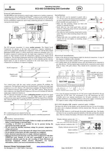
Safety SymbolsCaution, warning and danger use a variety of safety symbols to depict the specificrisk. These symbols are used throughout this manual.DANGEROUSTEMPERATURESELECTRICALHAZARDAIR GAS INLETPRESSUREMOVING PARTSCUT AND CRUSHHIGH PRESSUREFLAMMABLEEXPLOSIVEASPHYXIATIONPINCH POINTLIFTING HAZARDTOXIC AND POISONOUSSUBSTANCESFALLING DO NOTCLIMB ON EQUIPMENTSLIPPING AND FALLINGGENERAL WARNINGGENERAL DANGERROTATINGCOMPONENTSEVER HAZARDPROJECTILEPERSONAL PROTECTIVEEQUIPMENTF i gu re 1 Safety symbolsThe safety advisories in this book are set against a blackbackground so that they stand out. When using these signson equipment, the background is safety white with a blackborder and black text.Complies with ANSI Z535, ISO 3864, OSHA 1910.145 (f) (9)H301/302 HSR Compressors Rev. 2.2 5
Technical SupportTechnical SupportTechnical support is available 24 hours/7 days a week; when youneed it.E-mail: hsr support@ge.comPhone: 1 832 978 9780Available 24 hrs1-832-978-9780hsr support@ge.comTrainingTraining is available three times a year. The schedule is posted on theHSR website http://supportcentral.ge.com/products/sup products.asp?prod id 51671.WarrantyThe warranty is effective when:Warranty1.2.3.4.GE Oil & GasATTN: Warranty Administrator- HSR Compressors4425 Westway Park Blvd.Mailstop #3Houston, TX 77041 USAhsr support@ge.com6 Chapter 1: Getting StartedAn authorized representative of GE Oil & Gas – High SpeedReciprocating (HSR) gas compressors or the authorized packageris present at the initial start-upAll frame and cylinder assembly components received properpre-start maintenance checks and lubrication as stated in thismanualStarting and operating the compressor within the design limitsand HSR Compressor specifications
Document Revision Chart The following chart lists the revisions made to this document tracked by version. Revision Revision description Date Author Approver