Transcription
A/C COMPRESSOR SERVICING 1998 Pontiac Bonneville1998 GENERAL SERVICINGGeneral Motors Corp. - Compressor ServicingBODY DESIGNATIONSBODY DESIGNATIONS (CARS) TABLE Model(1) Body DesignationAchieva, Cutlass, Grand Am,Malibu & Skylark .Aurora & Riviera .Bonneville, Eighty EightLeSabre, LSS & Regency .Camaro & Firebird .Catera .Cavalier & Sunfire .Century, Grand Prix, Intrigue,Lumina, Monte Carlo & Regal .Concours, DeVille & Seville .Corvette .Eldorado .Metro .Park Avenue .Prizm .Saturn ."N" Body"G" "S""Z"BodyBodyBodyBodyBodyBodyBodyBody(1) - Body codes are determined by fourth character of VINcode. BODY DESIGNATIONS (LIGHT TRUCKS & VANS) TABLE Model(1) Body DesignationAstro & Safari2WD .4WD .Blazer, Bravada, Jimmy, Pickup & Sonoma2WD .4WD .Commercial Van & Chassis .Express, G-Van & Savanna (Van) .Pickup, Sierra, Suburban Tahoe & Yukon2WD .4WD .Tracker .Silhouette, Trans Sport & Venture ."M" Series"L" ""U"SeriesSeriesSeriesSeries(1) - Series codes are determined by fifth character of VINcode. COMPRESSOR APPLICATIONSCOMPRESSOR APPLICATIONS TABLE ApplicationCompressor
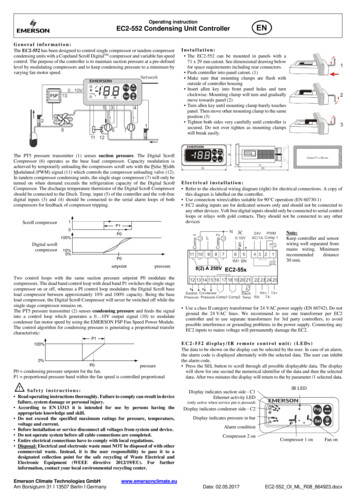
Cars (1)"C" Body . Harrison V5 5-Cyl."E" Body . Harrison HD6/HT6 6-Cyl."K" Body . Harrison HD6/HT6 6-Cyl."F" Body3.8L Engine . Harrison V5 5-Cyl.5.7L Engine . Harrison V7 7-Cyl."G" BodyAurora . Harrison HD6/HT6 6-Cyl.Riviera . Harrison V5 5-Cyl."H" Body . Harrison V5 5-Cyl."J" Body . Harrison V5 5-Cyl."M" Body . Nippondenso 10-Cyl."N" Body . Harrison V5 5-Cyl."S" Body . Harrison V5 5-Cyl."V" Body . Harrison V5 5-Cyl."W" Body . Harrison V5 5-Cyl."Y" Body . Harrison V7 7-Cyl."Z" Body . Zexel Rotary VaneLight Trucks & Vans (2)"C" & "K" Series . Harrison HD6/HT6 6-Cyl."G" Series . Harrison V5 5-Cyl."J" Series . Nippondenso 10-Cyl."L" & "M" Series . Harrison HD6/HT6 6-Cyl."P" Series . Harrison HD6/HT6 6-Cyl."S" & "T" Series2.2L . Harrison V7 7-Cyl.4.3L . Harrison HD6/HT6 6-Cyl."U" Series . Harrison V5 5-Cyl.(1) - Body codes are determined by fourth character ofVIN code.(2) - Series codes are determined by fifth character ofVIN code. HARRISON HD6/HT6, HARRISON V5 5-CYL. & V7 7-CYL.CLUTCH ASSEMBLYCAUTION: DO NOT hammer on compressor shaft to remove clutch plate, ascompressor damage will result.Removal1) Remove compressor from vehicle. Place compressor inHolding Fixture (HD6/HT6 compressor use J-33026; on V5 or V7compressor use J-34992 or J-41790). On V5 or V7 compressor, removedust cover (if equipped). Use Clutch Plate Spanner (J-33027-A) to holdclutch plate and remove compressor shaft nut using Shaft Nut Socket(J-33022). See Fig. 1 or 2.2) On all compressors, using Clutch Plate Remover/Installer(J-33013-B), remove compressor clutch plate and hub. See Fig. 1 or 2.Hold remover body and turn center screw into remover body to removeclutch plate and hub. Ensure forcing tip on remover/installer centerscrew is flat or end of shaft/axial plate will be damaged. Removeshaft key.3) Remove snap ring. Install Puller Guide (J-33023-A) onfront head. Position Pulley and Bearing Puller (J-41552 for HD6/HT6 orJ-33020 for V5 or V7 compressor) into inner circle of slots on pulleyassembly. Turn puller clockwise in slots. Tighten puller and remove
pulley assembly.4) If bearing is to be removed, remove forcing screw frompuller. With puller still engaged in pulley slots, invert assemblyonto a solid flat surface. Use a hammer and Bearing Remover (J-9398-A)to drive bearing from pulley. See Fig. 1 or 2.NOTE:It is not necessary to remove staking in front of bearingbefore removing bearing.5) Disconnect clutch coil lead. Scribe marks on compressorand clutch coil for installation reference. Remove clutch coil usingPuller Adapter (J-33023-A) and 2-jaw puller.Installation1) Align reference marks made during removal. Using PullerAdapter (J-33024) and Puller Bar (J-8433-1), press clutch coil ontocompressor. Ensure clutch coil and installer stay lined up duringinstallation. Using a 1/8" punch, stake clutch coil inner ring in 3places, 120 degrees apart. Stake size should be 1/2 the area of punchtip and 0.010-0.015" (0.28-0.38 mm) deep.NOTE:To ensure proper bearing clearance, it is necessary toremove old stake metal before installing a NEW bearing.2) To install pulley bearing, place pulley on Support (J21352-A). DO NOT support pulley rim on flat surface, or pulley will bedamaged. Install bearing in pulley using hammer, Bearing Installer (J9481-A) and Handle (J-29886).3) With pulley on support, use Bearing Staking Guide (J33019-1) and Bearing Staking Pin (J-33019-2) to stake pulley in 3places, 120 degrees apart. Reposition pulley on support to ensure fullsupport under staking pin. Metal stake should be similar to originalstake (down to, but not touching bearing). Position pulley oncompressor.4) Place Bearing Installer (J-33017) and Puller Guide (J33023-A) over inner race of bearing. Using puller, press pulley ontocompressor. Install snap ring. Install shaft key in clutch plate,allowing key to protrude about 1/8" from rear of clutch plate.5) Install clutch plate on compressor shaft. Using clutchplate remover/installer, press clutch plate onto compressor. Ensureshaft key is still in keyway before installing clutch assembly.6) Air gap between friction surfaces for HD6/HT6 compressoris 0.020-0.030" (0.51-0.76 mm); for V5 and V7 compressor air gap is 0.015-0.020" (0.38-0.51 mm). On V5 and V7 compressor, using clutch platespanner, install compressor shaft nut. Tighten shaft nut to 12.5 ft.lbs. (17 N.m). Check components for proper rotation.
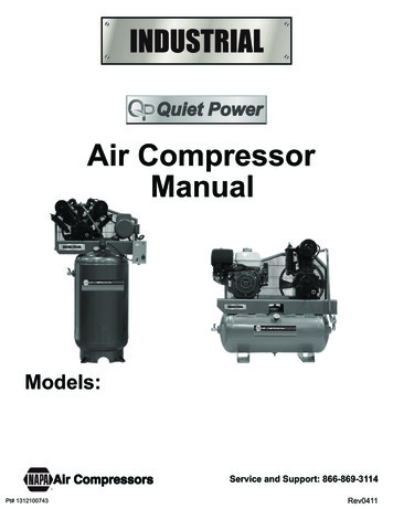
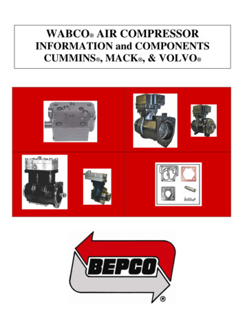
Fig. 1: Compressor Components (Harrison HD6/HT6 6-Cylinder)Courtesy of General Motors Corp.
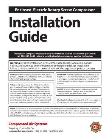
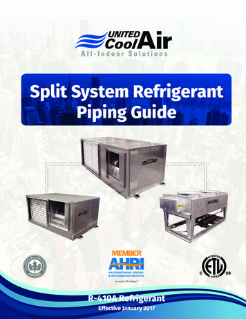
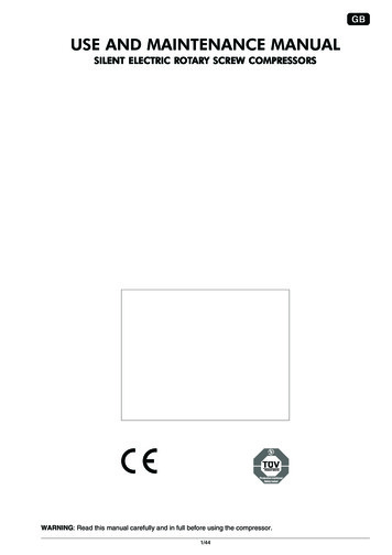
Fig. 2: Compressor Components (Harrison V5 5-Cylinder Shown;V7 7-Cylinder Is Similar)Courtesy of General Motors Corp.SHAFT SEAL
NOTE:It is not necessary to replace shaft seal because of a smallamount of oil found on adjacent surfaces. A small amount ofoil is normal for lubrication purposes. Shaft seal shouldonly be replaced after a confirmed refrigerant leak is found.Removal1) Discharge A/C system, using approved refrigerantrecovery/recycling equipment. Loosen and reposition compressor inmounting bracket. Remove clutch plate and hub assembly. See CLUTCHASSEMBLY. See Fig. 1 or 2.2) Remove shaft seal snap ring. Ensure all surfaces aroundseal are clean. Insert Shaft Seal Remover/Installer (J-23128-A) intoshaft seal. Rotate handle clockwise to seat seal remover/installer inseal. Remove shaft seal. Using "O" Ring Remover (J-9553-01), remove"O" ring. Ensure shaft and inside of compressor neck are clean andfree of foreign material. Thoroughly clean "O" ring groove in fronthead.Installation1) Install Shaft Seal Protector (J-34614) over compressorshaft. With shaft seal protector in place, lubricate NEW "O" ring withrefrigerant oil and install it on "O" Ring Installer (J-33011).2) Insert "O" ring installer in compressor until it bottoms.Move slide on "O" ring installer downward until "O" ring is releasedinto groove. Rotate installer to seat "O" ring. Remove "O" ringinstaller.3) Lubricate shaft seal with NEW refrigerant oil. Installshaft seal onto Seal Installer (J-23128-A). Install shaft seal soflared side of lip seal is installed toward compressor. Expand sealusing shaft seal remover/installer. Install shaft seal on SealProtector (J-34614). Place seal protector over shaft.4) Push shaft seal into compressor using a rotary motionuntil seal bottoms. Install NEW snap ring with flat side against seal.Install clutch plate and hub assembly onto compressor shaft. SeeCLUTCH ASSEMBLY.NIPPONDENSO 10-CYLINDERCLUTCH ASSEMBLYRemoval & Installation (Metro & Tracker)1) Discharge A/C system, using approved refrigerantrecovery/recycling equipment. Remove compressor. Drain, measure anddiscard refrigerant oil from compressor.2) Using Clutch Plate Holder/Remover (J-41384) remove clutchplate nut, washer and clutch plate from compressor drive shaft. Removeclutch pulley snap ring and shim. Using a plastic mallet, gently tapand remove clutch pulley. Remove clutch coil wire retainer fromcompressor. Remove clutch coil snap ring and clutch coil. See Fig. 3.3) Install clutch coil and snap ring. Attach clutch coil wireretainer to compressor. Install clutch pulley, snap ring and shim.Install clutch plate to compressor shaft. Measure air gap betweenclutch pulley and clutch plate.4) Air gap should be 0.014-0.026" (0.35-0.65 mm). Add orremove shims as necessary. Install compressor shaft nut and washer.Tighten compressor shaft nut to 11-15 ft. lbs. (15-20 N.m). Afterrepairs, add NEW refrigerant oil to compressor equal to amountdrained. To complete installation, reverse removal procedure.SHAFT SEAL
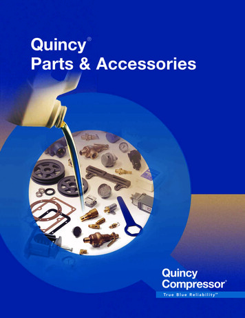
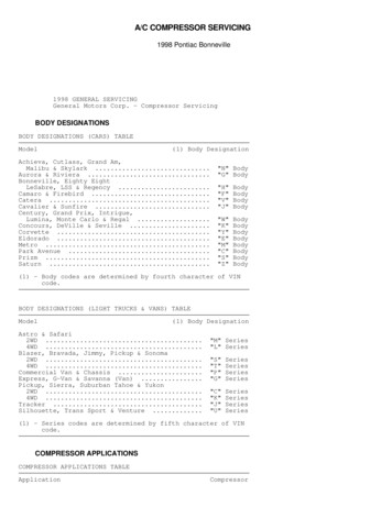
Removal1) Discharge A/C system, using approved refrigerantrecovery/recycling equipment. Remove compressor. Drain, measure anddiscard refrigerant oil from compressor. Remove clutch plate, clutchpulley, shims, and clutch coil. See CLUTCH ASSEMBLY. See Fig. 3.2) Using a flat-blade screwdriver, remove felt ring and feltwasher from front housing. Remove shaft key and shaft seal snap ring.Insert Compressor Shaft Seal Remover/Installer (J-33942-B) into seal.Turn seal remover/installer until contact with notches in seal ismade. Remove shaft seal.Installation1) Install Compressor Shaft Seal Protector (J-34614) ontocompressor shaft. Lubricate NEW shaft seal with refrigerant oil. DONOT touch sealing surfaces. Engage seal remover/installer into sealnotches and install seal onto compressor shaft. Remove seal protectorand remover/installer.2) Install seal snap ring. Install felt washer and felt ring.Install clutch plate, clutch pulley, shims, and clutch coil. SeeCLUTCH ASSEMBLY. See Fig. 3. After repairs, add NEW refrigerant oil tocompressor equal to amount drained. To complete installation, reverseremoval procedure. Perform leak test.Fig. 3: Compressor Components (Nippondenso 10-Cylinder)Courtesy of General Motors Corp.ZEXEL ROTARY VANE
CLUTCH ASSEMBLYNOTE:Discharging A/C system and removing refrigerant lines fromcompressor is not necessary to service clutch assembly.Removal1) Loosen tensioner and remove drive belt from pulley.Disconnect clutch electrical connector. Remove compressor mountingbolts. With refrigerant lines connected lift compressor upward andforward. Install one front mounting bolt through bottom rearcompressor mounting ear. Tighten bolt so compressor is supported bymounting bracket.2) Using Clutch Drive Plate Holder (SA9510AC), remove clutchdrive plate center bolt. Insert Clutch Drive Plate Remover Sleeve(SA9506AC) into center of drive plate. Install remover bolt. Whileholding clutch remover sleeve, tighten remover bolt and remove driveplate and shims.3) Remove pulley external snap ring. Position Puller CenterAdapter (SA9149AC-2) over end of compressor shaft. Attach 3-jaw pullerto back of pulley. Tighten puller bolt against pulley center adapterand remove pulley. Remove clutch coil screws. Disconnect clutch coilwire. Remove clutch coil.Installation1) Install coil in original position. Ensure electricalconnector is aligned with indent in front of compressor head. Tightenscrews to 44 INCH lbs. (5 N.m). Place Drive Plate Installer (SA9149AC3) and thrust bearing on installation bolt and insert through centerof pulley. Finger-tighten pulley installation bolt into compressorshaft.2) Finger-tighten nut on installation bolt to align pulley tocompressor. Hold end of bolt and tighten nut until pulley bottoms oncompressor. Loosen nut and remove installation bolt, thrust bearingand drive plate installer. Install snap ring with tapered side out.3) Install thrust bearing on installation bolt and insertthrough clutch drive plate. Place original shims on installation bolt.Thread bolt into compressor shaft. Hold end of bolt and tighten nutuntil clutch drive plate bottoms out. Loosen nut and removeinstallation bolt and thrust bearing. Install center bolt and tightento 115 INCH lbs. (13 N.m) using clutch drive plate holder.4) Using a feeler gauge, measure air gap between drive plateand pulley. Air gap should be 0.018-0.030" (0.46-0.76 mm). If air gapis not as specified, add or remove shims as necessary. Installcompressor onto mounting bracket. Tighten front bolts to 36 ft. lbs.(49 N.m) and rear bolts to 19 ft. lbs. (26 N.m). Connect clutchelectrical connector and install accessory drive belt.5) Start engine and allow it to idle. Turn A/C on and cyclecompressor on and off 10-15 times to break-in NEW clutch drive plateand pulley assembly.
Install clutch plate to compressor shaft. Measure air gap between clutch pulley and clutch plate. 4) Air gap should be 0.014-0.026" (0.35-0.65 mm). Add or remove shims as necessary. Install compressor shaft nut and washer. Tighten compressor shaft nut to 11-15 ft. lbs. (15-20 N.m). After repairs, add NEW refrigerant oil to compressor equal to .