Transcription
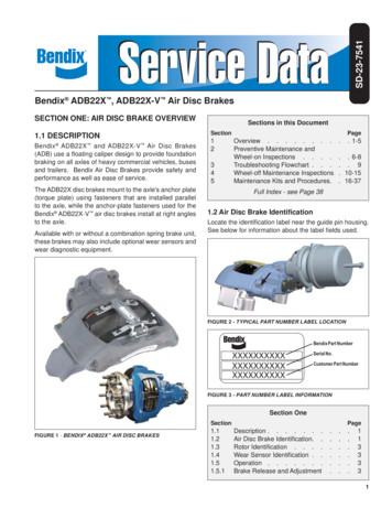
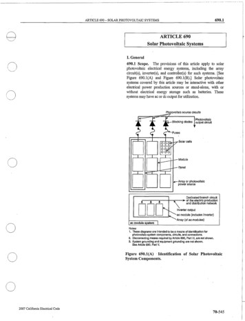
SD-01-690BENDIX BA-921 COMPRESSORDESCRIPTIONThe function of the air compressor is to provide and maintainair under pressure to operate devices in air brake systems.The Bendix BA-921 compressor is a single-cylinderreciprocating compressor with a rated displacement of15.8 cubic feet per minute at 1250 RPM.SafetyValveCylinderHeadValve PlateAssemblyThe compressor consists of a water-cooled cylinderhead assembly and an integral air-cooled crankcaseassembly.CoolingPlateThe cylinder head assembly is made up of the cylinderhead, cooling plate and valve plate assembly and usestwo sealing gaskets. Depending on the application, thecylinder head and cooling plate may be aluminum or castiron. The cylinder head contains air and water ports aswell as an unloader assembly. A cooling plate is locatedbetween the cylinder head and valve plate assemblies andassists in cooling.The valve plate assembly consists of brazed steel plateswhich have valve openings and passages for air and enginecoolant to flow into and out of the cylinder head. Thecompressor's discharge valves are part of the valve plateassembly. The inlet reed valve/gasket is installed betweenthe valve plate assembly and the top of the crankcase.SplashShieldCoolant Ports(3 es rankcaseCoverFIGURE 1 - BENDIX BA-921 COMPRESSOR (CUT-AWAY)CrankcaseFIGURE 2 - BENDIX BA-921 COMPRESSORThe cast iron crankcase houses the piston assembly,connecting rod, crankshaft and related bearings.All Bendix BA-921 compressors are equipped with asafety valve to protect the compressor head in the eventof, for example, a discharge line blockage downstreamof the compressor. Excessive air pressure will cause thesafety valve to unseat, release air pressure and give anaudible alert to the operator. The safety valve is installedin the cylinder head safety valve port, directly connectedto the cylinder head discharge port.The crankcase cover located at the bottom of the crankcaseis stamped with information identifying the compressormodel, customer piece number, Bendix piece number andserial number. See Figures 2 and 3.Compressor Model,Customer Piece Number,Bendix Piece Number andSerial Number shown hereFIGURE 3 - CRANKCASE BASE COVER
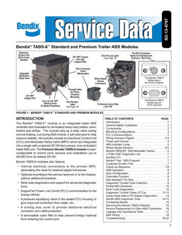
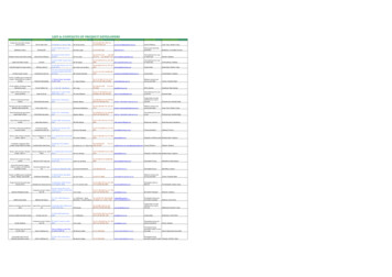
CaterpillarC7, C9EnginesCaterpillarHD AcertEnginesFIGURE 4 - TYPICAL COMPRESSOR DRIVE FLANGESDetroitDiesel S60piston to move upwards, away from its seat on the valveplate assembly. When the unloader piston is unseated anOPERATIONThe compressor is driven by the vehicle's engine andfunctions continuously while the engine is in operation.Actual compression of air is controlled by the compressorunloading mechanism operating in conjunction with agovernor.AIR INTAKE (LOADED)Just as the piston begins the down stroke, (a positionknown as top dead center, or TDC), the vacuum createdin the cylinder bore above the piston causes the inletreed valve to flex open. Atmospheric air (in naturallyaspirated applications) or pressurized air (in turbochargedapplications) flows through the open inlet valve and fills thecylinder bore above the piston. See Figure 5.AirDischargePortAir ateValvePlateUnloaderPistonDown &SeatedInletValveOpenAIR COMPRESSION (LOADED)When the piston reaches the bottom of the stroke, (aposition known as bottom dead center, or BDC), the inletreed valve closes. Air above the piston is trapped by theclosed inlet reed valve and is compressed as the pistonmoves upwards. When air in the cylinder bore reachesa pressure greater than that of the system pressure, thedischarge reed valves open and allow air to flow into thedischarge line and air brake system.At the same time air flows into the hollow center of theunloader piston through an opening in the end of the piston.Compressed air acts on the interior surfaces of the unloaderpiston and, along with the unloader piston spring, holds theunloader piston in the down position, against its seat onthe valve plate. See Figure 7.NON-COMPRESSION OF AIR (UNLOADED)When air pressure in the supply reservoir reaches thecutout setting of the governor, the governor deliverssystem air to the compressor unloader port. Air enteringthe unloader port acts on the unloader piston causing the2Piston Moving DownFIGURE 5 - OPERATION - LOADED (INTAKE)An Inlet Check Valve (ICV),or alternately, an ICV plus a reservoir,is used in the air inlet line depending onthe applicationAir DryerGovernorUnloader PortGovernorReservoirPortCompressorSupply ReservoirFIGURE 6 - BA-921 COMPRESSOR UNLOADER SYSTEM
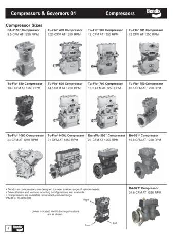
AirDischargePortAir InletPortDischargeValveOpenLubrication for Caterpillar C11 and C13 teUnloaderPistonDown &SeatedInletValveClosedPiston Moving UpFIGURE 7 - OPERATION - LOADED (COMPRESSION)air passageway is opened between the cylinder bore andthe air inlet cavity in the cylinder head.As the piston moves from bottom dead center (BDC) totop dead center (TDC) air in the cylinder bore flows pastthe unseated unloader piston, into the cylinder head inletcavity and out the inlet port. To prevent the air from flowingback into the engine air induction system, an inlet checkvalve (ICV) is installed upstream of the air compressor inletport. The location of the device and the way it is plumbedinto the compressor air induction system is unique to thespecific engine and the type of air induction (naturallyaspirated or boosted air) the compressor uses. These airinduction systems will be explained in further detail in the“Air Induction” section on page 4. On the piston downstroke (TDC to BDC) air flows in the reverse direction, fromthe inlet cavity past the unseated unloader piston and inletreed valve, and into the cylinder bore.LUBRICATIONThe vehicle's engine provides a continuous supply of oilto the compressor. Oil is routed from the engine to thecompressor's oil inlet. An oil passage in the crankshaftroutes pressurized oil to the precision sleeve main bearingsand to the connecting rod bearings. Spray lubrication ofthe cylinder bores, connecting rod wrist pin bushings, andball type main bearings is obtained as oil is forced outaround the crankshaft journals by engine oil pressure.Oil then falls to the bottom of the compressor crankcaseand is returned to the engine through drain holes in thecompressor mounting flange.Bendix BA-921 compressor - for Caterpillar C11 andC13 engine installations only - use an "oil jet" that spraysoil under the piston for purposes of cooling. This oil jetis part of a special crankcase cover that is used only onthe BA-921 compressor for CAT C11 and C13 engineinstallations (see Figure 14).This design slightly alters the flow of oil for lubrication. Theoil supply line from the engine is directly connected to theback side of the special crankcase over. The oil flows inparallel through a passageway in the crankcase cover andthrough the oil jet to spray oil under pressure up onto theunderneath of the piston for cooling. At the same time,oil flows out of the opposite end of the special crankcasecover, through a fitting and a metal tube and second fittinginto the oil supply port of the compressor. At this point oilflows in a similar manner as in the first paragraph of thissection.COOLINGBendix BA-921 compressors are cooled by air flowingthrough the engine compartment as it passes the compressor's cast-in cooling fins and by the flow of engine coolantthrough the cylinder head. Coolant supplied by the enginecooling system passes through connecting lines into thecylinder head and passes through internal passages inthe cylinder head, cooling plate and valve plate assemblyand returns to the engine. Figure 9 illustrates the variousapproved coolant flow connections. Proper cooling isimportant in minimizing discharge air temperatures - seethe tabulated technical data on page 14 of this manual forspecific requirements.Air Inlet PortCoolingPlateValvePlateAir FromGovernorUnloaderPortUnloaderPiston Up &UnseatedAir in Pistons Shuttles Back and Forth from thePiston to the Cylinder Head and Inlet Port DuringUnloaded ModeFIGURE 8 - OPERATION - UNLOADED3
AIR INDUCTIONHeadBolt (4)GENERALThe Bendix BA-921 air compressor can be used bothwith air induction systems that are naturally aspirated(atmospheric air) and pressurized (turbocharged). Thefollowing section covers Caterpillar and Detroit Dieselengine air induction arrangements. See Figure 4, fortypical flanges used.CATERPILLARCaterpillar HD ACERT engines (C11, C13, C15 and C18)and MD ACERT engines (C7 and C9) are typically equippedwith Bendix BA-921 compressors. These enginesprovide pressurized (turbocharged) air to the compressor'sinlet port. Caterpillar recommends the use of an inlet checkvalve in the air induction system to prevent the air from thecompressor being forced back into the engine air inductionsystem when the compressor is operating in the "unloaded"condition (not building air). Because the compressorinduction system is turbocharged, an additional air volume(reservoir) is required between the compressor inlet portand the inlet check valve to prevent excessive air pressureat the compressor inlet in the unloaded mode. Figures 10and 11 show example of the different air induction systemsused by Caterpillar to perform this function.CATERPILLAR C7/C9 ENGINESThe Bendix BA-921 compressor in the C7/C9 air inductionsystem (see Figure 10) receives its air from the engine'sintake manifold (turbocharged). During the pumpingcondition (loaded mode), the air flows from the engineintake manifold through the inlet check valve and inletline to the compressor inlet port. During the non-pumpingcondition (unloaded mode), the compressor cylinderpushes air back out of the inlet port to the inlet check valve.The ICV prevents the air from traveling beyond this point.Because the air is boosted (under pressure), it is importantthat the compressor inlet line is of sufficient length, strengthand volume to minimize the build-up of air pressure in theinlet system. The air shuttles back and forth between thecompressor cylinder bore and the ICV during this phaseof the compressor operation.DischargeSafety ValveCoolant In or Out(One or other not derCoverCoolant In or OutCYLINDER HEAD PORT IDENTIFICATIONThe cylinder head connection ports are identified with castin numerals as follows:AIR IN0Compressed AIR OUT2Coolant IN or OUT9Governor Control4FIGURE 9 - TYPICAL BENDIX BA-921 COMPRESSORCYLINDER HEADexpansion tank) prevents the air from traveling beyondthis point. Because the air is boosted (under pressure),it is important that the compressor inlet line is of sufficientlength, strength and volume to minimize the build-up of airpressure in the inlet system. The air shuttles back and forthbetween the compressor cylinder bore and the expansiontank during this phase of the compressor operation.InletPortInletLineCATERPILLAR C11, C13, C15 AND C18ENGINESThe Bendix BA-921 compressor in the C11, C13, C15,and C18 air induction systems (see Figure 11) receivesits air from the engine's intake manifold (turbocharged).During the pumping condition (loaded mode), the air flowsfrom the engine intake manifold through the inlet checkvalve, expansion tank and inlet line to the compressor inletport. During the non-pumping condition (unloaded mode),the compressor cylinder pushes air back out of the inletport into the expansion tank. The ICV (at the end of the4Inlet Check ValveAir SupplyFrom EngineFIGURE 10 - EXAMPLE OF CATERPILLAR (ACERTENGINE) C7/C9 COMPRESSOR AIR INDUCTION SYSTEM(TURBOCHARGED)
InletLineExpansion TankInletPortAir SupplyFrom EngineDuring operation, non-pressurized air from the engine'sair source is routed to the compressor from a pointbetween the engine air filter and the non-pressure sideof the turbocharger. When the compressor is buildingair (loaded mode), the air flows from the engine intaketube, through the inlet check valve into the inlet port ofthe compressor. When the compressor is not building air(unloaded mode), the compressor pushes the air back outthe compressor during the cylinder upstroke towards theinlet check valve. The ICV prevents the air from travelingbeyond this point. The air shuttles back and forth betweenthe compressor cylinder bore and the ICV during this phaseof the compressor operation.PREVENTATIVE MAINTENANCEInlet Check ValveFIGURE 11 - EXAMPLE CATERPILLAR (HD ACERTENGINE) C11/C13/C15/C18 COMPRESSOR AIR INDUCTIONSYSTEM (TURBOCHARGED)DETROIT DIESELThe Detroit Diesel Series 60 (EGR) engine is equippedwith the Bendix BA-921 compressor and uses naturallyaspirated air induction system. Detroit Diesel recommendsthe use of an inlet check valve in the air induction systemto prevent the air from the compressor cylinder bore frombeing forced back into the engine air induction system whenthe compressor is in the unloaded mode (non-pumpingcondition). A flexible high-pressure hose is installedbetween the inlet check valve and the compressor inletfitting. This hose can be of various lengths to accommodatethe distance between the compressor and inlet check valve.See Figure 12.AFrInletCheckValveInletPortRegularly scheduled maintenance is the single mostimportant factor in maintaining the air brake chargingsystem. Refer to Table A in the Troubleshooting section onpage 17, for a guide to various considerations that must begiven to maintenance of the compressor and other relatedcharging system components.Important Note: Review the warranty policy beforeperforming any intrusive maintenance procedures. Anextended warranty may be voided if intrusive maintenanceis performed during this period.EVERY 6 MONTHS, 1800 OPERATING HOURSOR AFTER EACH 50,000, MILES WHICHEVEROCCURS FIRST, PERFORM THE FOLLOWINGINSPECTIONS AND TESTS.AIR INDUCTIONThe Bendix BA-921 compressor is designed forconnection to the vacuum side of the engine’s air inductionsystem and the pressure side (turbocharged) of theengine’s air induction system.A supply of clean air is one of the single most importantfactors in compressor preventive maintenance. Sincethe air supply for BA-921 compressor and engine is theengine air cleaner, periodic maintenance of the engine airfilter is necessary.Inspect the compressor air induction system each timeengine air cleaner maintenance is performed.1. Inspect the intake hose adapters for physical damage.Make certain to check the adapters at both ends of theintake hose or tubing.2. Inspect the intake hose clamps and tighten them ifneeded.3. Inspect the intake hose or line for signs of drying, cracking,chafing and ruptures and replace if necessary.FIGURE 12 - EXAMPLE OF DETROIT DIESEL (EGR) S60COMPRESSOR AIR INDUCTION SYSTEM (NATURALLYASPIRATED)4. Verify that the compressor inlet fitting is tight (checktorque).5
5. Any metal tubes should also be tight (torqued properly)to the mating fitting. Inspect the metal tubes for anycracks or breaks and replace if necessary.6. If an expansion tank is present (turbocharged airinduction systems only), inspect any cracks and replaceif necessary.COMPRESSOR COOLINGInspect the compressor discharge port, inlet cavity anddischarge line for evidence of restrictions and carbonbuildup. If more than 1/16" of carbon is found, thoroughlyclean or replace the affected parts. In some case, carbonbuildup indicates inadequate cooling. Closely inspect thecompressor cooling system. Check all compressor coolantlines for kinks and restrictions to flow. Minimum coolant linesize is 3/8" I.D. Check coolant lines for internal cloggingfrom rust scale. If coolant lines appear suspicious, checkthe coolant flow and compare to the tabulated technicaldata present in the back of this manual. Carefully inspectthe air induction system for restrictions.LUBRICATIONCheck the external oil supply line for kinks, bends, orrestrictions to flow. Supply lines must be a minimum of3/16” I.D. Refer to the tabulated technical data in the backof this manual for oil pressure minimum values.Check the exterior of the compressor for the presence ofoil seepage and refer to the TROUBLESHOOTING sectionfor appropriate tests and corrective action.Note: This is applicable only for Caterpillar engineinstallations. Detroit Diesel utilizes an internal oil feeddesign. No external oil supply line is used.OIL PASSINGAll reciprocating compressors pass a minimal amount ofoil. Air dyers will remove the majority of oil before it canenter the air brake system. For particularly oil sensitivesystems, the Bendix PuraGuard system can be use inconjunction with a Bendix air dryer.If compressor oil passing is suspected, refer to theTROUBLESHOOTING section and TABLE A for thesymptoms and corrective action to be taken. In addition,Bendix has developed the “Bendix Air System InspectionCup” or BASIC kit to help substantiate suspectedexcessive oil passing. The steps to be followed when usingthe BASIC kit are presented in APPENDIX A at the endof the TROUBLESHOOTING section.6COMPRESSOR DRIVECheck for noisy compressor operation, which could indicateexcessive drive component wear. Adjust and/or replaceas necessary. Check all compressor mounting bolts andretighten evenly if necessary. Check for leakage andproper unloader mechanism operation. Repair or replaceparts as necessary.COMPRESSOR UNLOADER & GOVERNORTest and inspect the compressor and governor unloadersystem for proper operation and pressure setting.1. Check for leakage at the unloader port. Replace leakingor worn o-rings.2. Make certain the unloader system lines are connectedas illustrated in Figure 6.3. Cycle the compressor through the loaded and unloadedcycle several times. Make certain that the governorcuts-in (compressor resumes compressing air) at aminimum of 105psi (cut-out should be approximately 15- 20psi greater than cut-in pressure). Adjust or replacethe governor as required.4. Note that the compressor cycles to the loaded andunloaded conditions promptly. If prompt action is notnoted, repair or replace the governor and/or repair thecompressor unloader.IMPORTANT NOTEReplacement air governors must have a minimum cut-inpressure of 100psi. The cut-in pressure is the lowestsystem pressure registered in the gauges before thecompressor resumes compressing air.Compressors with no signal line to the unloader port shouldhave a vent cap (e.g. Bendix part number 222797) installedin the port. Under no circumstances should the port beplugged or left open.SERVICE TESTSGENERALThe following compressor operating and leakage tests neednot be performed on a regular basis. These tests should beperformed when it is suspected that leakage is substantiallyaffecting compressor buildup performance, or when it issuspected that the compressor is “cycling” between theloaded (pumping) and unloaded (non-pumping) modesdue to unloader leakage.
IN SERVICE OPERATING TESTSCYLINDER HEADCompressor Performance: Build-up TestCheck for cylinder head gasket air leakage.This test is performed with the vehicle parked and the engineoperating at maximum recommended governed speed.Fully charge the air system to governor cut out (air dryerpurges). Pump the service brake pedal to lower the systemair pressure below 80 psi using the dash gauges. As the airpressure builds back up, measure the time from when thedash gauge passes 85 psi to the time it passes 100 psi. Thetime should not exceed 40 seconds. If the vehicle exceeds40 seconds, test for (and fix) any air leaks, and then re- testthe compressor performance. If the vehicle does not passthe test the second time, use the Advanced TroubleshootingGuide for Air Brake Compressors, starting on page 15 of thisdocument to assist your investigation of the cause(s).1. With the engine running, lower air system pressure to60 psi and apply a soap solution around the cylinderhead. Check the gasket between the cylinderhead and valve plate assembly and the inlet reedvalve/gasket between the valve plate assembly andcrankcase for air leakage.Note: All new vehicles are certified using the FMVSS 121 test(paragraph S5.1.1) by the vehicle manufacturer, however theabove test is a useful guide for in-service vehicles.Optional Comparative Performance CheckIt may be useful to also conduct the above test with the enginerunning at high idle (instead of maximum governed speed),and record the time taken to raise the system pressure aselected range (for example, from 90 to 120 psi, or from 100 to120 psi, etc.) and record it in the vehicle’s maintenance files.Subsequent build-up times throughout the vehicle’s servicelife can then be compared to the first one recorded. (Note:the 40 second guide in the test above does not apply to thisbuild-up time.) If the performance degrades significantly overtime, you may use the Advanced Troubleshooting Guide forAir Brake Compressors, starting on page 15 of this document,to assist investigation of the cause(s).Note: When comparing build-up times, be sure to make anallowance for any air system modifications which would causelonger times, such as adding air components or reservoirs.Always check for air system leakage.LEAKAGE TESTSSee the standard Air Brake System and Accessory Leakagetest on Page 28 (Test 2).Note: Leakage in the air supply system (components beforethe supply reservoir - such as the governor, air dryer, reservoirdrain cocks, safety valve and check valves) will not beregistered on the vehicle dash gauges and must be testedseparately. Refer to the various maintenance manuals forindividual component leakage tests and the Bendix “Testand Checklist” published in the Air Brake System Handbook(BW5057) and on the back of the Dual Circuit Brake SystemTroubleshooting Card (BW1396).2. No leakage is permitted. If leakage is detectedreplace the compressor or repair the cylinder headusing a genuine Bendix maintenance kit availablefrom an authorized Bendix parts outlet.INLET, DISCHARGE & UNLOADERIn order to test the inlet and discharge valves and theunloader piston, it is necessary to have shop air pressureand an assortment of fittings. A soap solution is alsorequired.1. With the engine shut off, drain ALL air pressure fromthe vehicle.2. Disconnect the inlet and discharge lines and removethe governor or its line or adapter fitting.3. Apply 120-130 psi shop air pressure to the unloaderport and soap the inlet port. Leakage at the inlet portshould not exceed 50 sccm.4. Apply 120-130 psi shop air pressure to the dischargeport and then apply and release air pressure to theinlet port. Soap the inlet port and note that leakageat the inlet port does not exceed 20 sccm.If excessive leakage is noted in Tests 3 or 4, replaceor repair the compressor using genuine Bendixreplacements or maintenance kits available from anyauthorized Bendix parts outlet.While it is possible to test for inlet, discharge, andunloader piston leakage, it may not be practical to doso. Inlet and discharge valve leakage can generally bedetected by longer compressor build-up and recoverytimes. Compare current compressor build-up times withthe last several recorded times. Make certain to testfor air system leakage, as described under In ServiceOperating Tests, before making a determination thatperformance has been lost.Unloader leakage is generally exhibited by excessivecompressor cycling between the loaded and unloadedcondition.1. With service and supply system leakage below themaximum allowable limits and the vehicle parked,bring system pressure to governor cut-out and allowthe engine to idle.7
2. The compressor should remain unloaded for a minimumof 5-10 minutes. If compressor cycling occurs morefrequently and service and supply system leakage iswithin tolerance replace the compressor or repair thecompressor unloader system using a genuine Bendixmaintenance kit available from authorized Bendix partsoutlets.COMPRESSOR REMOVAL & DISASSEMBLYGENERALThe following disassembly and assembly procedure ispresented for reference purposes and presupposes thata rebuild or repair of the compressor is being undertaken.Several maintenance kits are available and the instructionsprovided with these parts and kits should be followed inlieu of the instructions presented here.MAINTENANCE KITS & SERVICE PARTSCylinder Head Gasket Kit .5008558Unloader Kit .5008557Governor Adapter Kit .5008561Compressor Seal Kit (crankcase).5008559Components and kits for Caterpillar EnginesCAT C7/C9 Inlet Check Valve .801580CAT C11/C13/C15/C18 Inlet Check Valve .801592CAT C7/C9 Engine Seal Kit.5012367CAT C11/C13/C15/C18 Engine Seal Kit .5012369CAT ST-4 Discharge Safety Valve (7/8"-14 thrd.) .801116Components and kits for DDC EnginesDDC Inlet Check Valve .802192DDC Series 60 Engine Seal Kit .5012371DDC ST-4 Discharge Safety Valve (M16-1.5 thrd.) .800534IMPORTANT! PLEASE READ AND FOLLOWTHESE INSTRUCTIONS TO AVOID PERSONALINJURY OR DEATH:When working on or around a vehicle, the following generalprecautions should be observed at all times:1. Park the vehicle on a level surface, apply the parkingbrakes, and always block the wheels. Always wearsafety glasses. Where specifically directed, theparking brakes may have to be released, and/orspring brakes caged, and this will require that thevehicle be prevented from moving by other meansfor the duration of these tests/procedures.2. Stop the engine and remove ignition key whenworking under or around the vehicle. Whenworking in the engine compartment, the engineshould be shut off and the ignition key should beremoved. Where circumstances require that theengine be in operation, EXTREME CAUTION should8be used to prevent personal injury resulting fromcontact with moving, rotating, leaking, heated orelectrically charged components.3. Do not attempt to install, remove, disassembleor assemble a component until you have readand thoroughly understand the recommendedprocedures. Use only the proper tools and observeall precautions pertaining to use of those tools.4. If the work is being performed on the vehicle’sair brake system, or any auxiliary pressurized airsystems, make certain to drain the air pressure fromall reservoirs before beginning ANY work on thevehicle. If the vehicle is equipped with an AD-IS air dryer system or a dryer reservoir module, besure to drain the purge reservoir.5. Following the vehicle manufacturer’s recommendedprocedures, deactivate the electrical system in amanner that safely removes all electrical powerfrom the vehicle.6. Never exceed manufacturer’s recommendedpressures.7. Never connect or disconnect a hose or linecontaining pressure; it may whip. Never removea component or plug unless you are certain allsystem pressure has been depleted.8. Use only genuine Bendix replacement parts,components and kits. Replacement hardware,tubing, hose, fittings, etc. must be of equivalentsize, type and strength as original equipment andbe designed specifically for such applications andsystems.9. Components with stripped threads or damagedparts should be replaced rather than repaired. Donot attempt repairs requiring machining or weldingunless specifically stated and approved by thevehicle and component manufacturer.10. Prior to returning the vehicle to service, makecertain all components and systems are restoredto their proper operating condition.11. For vehicles with Antilock Traction Control (ATC),the ATC function must be disabled (ATC indicatorlamp should be ON) prior to performing any vehiclemaintenance where one or more wheels on a driveaxle are lifted off the ground and moving.
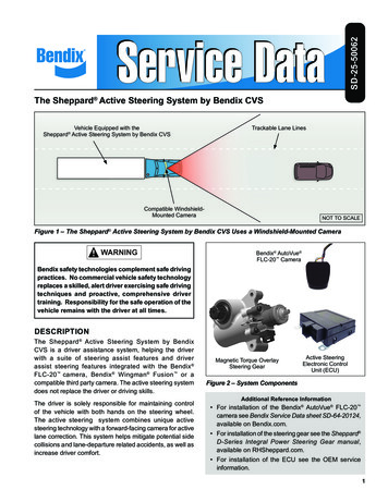
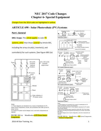
1 Head Cap Screws (4)(include washers)2 Unloader Cover Cap Screws (2)3 Unloader Cover Splash Shield6 Unloader Balance Piston7 O-Ring8 Spring9 O-Ring4 Unloader Cover5 Unloader Cover Gasket12 ST-4 Safety Valve10 Unloader Piston11 O-Ring13 Cylinder Head14 Head Gasket(2)AlignmentBushings16 Valve PlateAssembly15 CoolingPlate30GovernorGasket (2)17 Inlet Reed Valve/Gasket31GovernorAdapter19 CylinderRod18 Cylinder32 BoltwithWasher(2)CrankcaseAlignmentPins20 BearingSleeve22 Crankshaft21 Crankcase23 Rear Bearing27 Bottom CoverGasketItem Qty.1422314** 15** 16** 17** 18** 19** 110** 111** 112 113 114* 215 116 117* 118 119 120 121 122 1DescriptionHead Cap ScrewsUnloader Cover Cap ScrewsUnloader Cover Splash ShieldUnloader CoverUnloader Cap GasketUnloader Balance PistonO-RingSpringO-RingUnloader PistonO-RingST-4 Safety ValveCylinder HeadHead GasketsCooling PlateValve Plate AssemblyInlet Reed Valve/GasketCylinderCylinder RodSleeve BearingCrankcaseCrankshaft24 O-Ring25 Rear EndCover28 CrankcaseCoverItem Qty.23 124 125 126 427 128 129 430*** 231*** 132*** 229 CapScrews (4)DescriptionRear BearingO-RingRear End CoverCap ScrewsBottom Cover GasketCrankcase CoverCap ScrewsGovernor GasketGovernor AdapterBolt with Washer26 CapScrews (4)Notes:* included in Cylinder Head Gasket Kit(5008558)** included in Unloader Kit (5008557)*** included in Governor Adapter Kit(5008561)Crankcase Compressor Seal Kit (5008559)Unique Engine Seal Kits are available, forCat C7/C9 Engine, Cat C11/C13/C15/C18Engines, and DDC Series 60 EnginesFIGURE 13 – BA-921 COMPRESSOR EXPLODED VIEW9
REMOVALIn many instances it may not be necessary to remove thecompressor from the vehicle when installing the variousmaintenance kits and service parts. The maintenancetechnician must assess the installation and determine thecorrect course of action.These instructions are general and are intended to bea guide. In some cases additional preparations andprecautions are necessary. In all cases follow theinstructio
The function of the air compressor is to provide and maintain air under pressure to operate devices in air brake systems. The Bendix BA-921 compressor is a single-cylinder reciprocating compressor with a rated displacement of 15.8 cubic feet per minute at 1250 RPM. The compressor consists of a water-cooled cylinder