Transcription
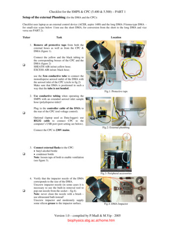
Checklist for the SMPS & CPC (5.400 & 5.500) – PART 1Setup of the external Plumbing (for the DMA and the CPC):Checklist uses laptop as an external control device (ACER, aspire 1400) and the long DMA (Vienna-type DMA for small-size scans below 11nm use the short DMA; for conversion from the short to the long DMA and viceversa see PART 2).TickerTaskLocation1. Remove all protective taps from both theexternal hoses as well as from the CPC &DMA (figure 1). Connect the yellow and the black tubing tothe corresponding bosses of the CPC and theDMA (figure 2)SHEATH AIR in/out yellow hose;EXCESS AIR in/out: black hose;use the 5cm conductive tube to connect themonodisperse aerosol outlet of the DMA withthe aerosol inlet of the CPC (circle in fig.2)Make sure that DMA is positioned in such away that the tube is not bended.Fig.1: Protective taps2. Use conductive tubing when operating theSMPS with an extended aerosol inlet samplehose (polydisperse-inlet)! Plug in the controller cable of the DMA tothe rear of the CPC (rod voltage control).Optional (laptop used as Data-logger): useRS232 cable to connect CPC to thecomputer’s USB port (port setting see below).Fig.2: External plumbingConnect the CPC to 230V mains. 3. Connect external flasks to the CPC: butyl-alcohol bottle condenser bottleNote: loosen taps of both to enable ventilation(see figure 3).Fig.3: Peripheral accessories 4. Verify that the impactor nozzle of the DMAcorresponds to the size of the DMA.Unscrew impactor nozzle (in some cases it isnecessary to use the built-in removal tool topop-out noozle from the socket – fig.4).Note: never clean the nozzle with a brush –use ultrasound bath instead!Unscrew impactor and moderately supplysome silicon grease to the impactor surface.Fig.4: DMA ImpactorVersion 1.0 – compiled by P.Madl & M.Yip - 2005biophysics.sbg.ac.at/home.htm
Checklist for the SMPS & CPC (5.400 & 5.500) – PART 1TickerTaskLocation5. Switch on the CPC (red wipe switch at therear panel – see fig.3); CPC enters intoCHARGE MODE (figure 5).Note: make sure the battery charge fuse is notbroken (above wipe switch – see fig.3); Press the ON/OFF key at front panel to bootCPC (display scrolls through step-1 till 5).Upon request, start “warm-up” by pressingthe -key (warm-up of saturator / cool-downof condensor); both Condenser and Saturatorstatus-LEDs turn red.Note: CPC will only become operational oncethese parameter-LEDs turn green.Fig.5: Booting the CPC 6. At the Computer: Launch SMPS software on PC;Note: stand-alone application using SMPS only (without laptop or PC): once status-LED turn green,press the standby-key to run the measurements; scans are performed in the normal scan mode!Check? (internal memorycard acts as data-logger); 7. open the Setup toolbox (step 1 in figure 7)and enter the desired parameters: slow / normal scan and long / short DMA(step 2 in figure 7);Note: scanning window can be restrictedusing the min/max scroll-down function; if known enter sample density; otherwiseset to 1.000 g/cm3;(step 3 in figure 7); COM-port / Baud rate(step 4 in figure 7); 8. Start measurement by clicking the: new icon (step 1 in figure 8); define FILE name and destination folder; activate the ONLINE icon; name file and choose destination folderand click the START icon (step 2 infigure 8);Note: start will be delayed as prior toeach order the instrument will undergoseveral parameter checks (leak test, zerocheck, sheath-air activation, etc.);9. Choose scan-mode representation (fig.9): number particle dist.: [dN/dln(dp)]; surface area distribution: [dS/dln(dp)] volume distribution: [dV/dln(dp)]; mass distribution: [dM/dln(dp)]; count distribution: [#/cm3];Terminate measurement by clicking theSTOP function;Note: Termination of an ongoing scan willcause the program to abort the last scan inprogress – the previous scans remain storedonto the file;Fig.7: Parameter-setup of scanning softwareFig.8: launching scans via the softwareFig.9: choose scan representation modeVersion 1.0 – compiled by P.Madl & M.Yip - 2005
Checklist for the SMPS & CPC (5.400 & 5.500) – PART 1Ticker TaskLocation10. Check CPC scan parameters (for eachmeasurement the following parameters areprotocoled): Numeric values: list of numeric entriesbased on the selected data format (step 1in figure 10); Instrumental data: on-line monitoringof battery reserves, air-pump current andcritical errors (step 2 in figure 10);Fig.10: choose scan representation mode11. Export file (after completion of themeasurement click STOP function andconvert files from SMPS file format toEXCEL-compatible format): Activate EXPORT function (step 1 infigure 11); Define mode (step 2 in figure 11); Click onto the Export icon (step 3 infigure 11); make sure the 1000-separatoris deactivated; Chose scan name and assign new namefor the exported file (steps 4 & 5 in figure11); Terminate scanning software;Fig.11: choose scan representation mode12. Import file into EXCEL: Click to DATA; Get External Data Import Text File .Fig.12: import SMPS file into Excel13. Import file into EXCEL (cont’d): Select exported SMPS file (step 1 infigure 13); Define Delimiters (step 2 in figure 11); Select the rows to be imported (step 3 infigure 11); Choose Data format (step 4 in figure 11); Define import location (step 5 in figure11);Fig.13: import selected SMPS fileVersion 1.0 – compiled by P.Madl & M.Yip - 2005
Checklist for the SMPS & CPC (5.400 & 5.500) – PART 114. Import file into EXCEL (cont’d): Right-click “Column A” of imported fileand insert an extra row (step 1 in figure14); Copy-paste content of “Row B” into“Row A” (step 2 in figure 14); Right-click “Row A” and set to standarddate format (step 3 in figure 14); Right-click “Row B” and set to standardtime format (step 4 & 5 in figure 14); Result should look like step 6 in figure14;Fig.14: Final touches of the imported SMPS file15. Proceed with further manipulation within EXCEL or any statistical software package available to generatedistribution plots with error bars / standard deviation / histograms / etc.Version 1.0 – compiled by P.Madl & M.Yip - 2005
Checklist for the SMPS & CPC (5.400 & 5.500) – PART 2Dismounting the Long DMA and assembling the Short DMA:Conversion from the long (Vienna-type) DMA to the short DMA should be performed in a clean environment;Ticker TaskLocation1. Prepare all utensils needed to perform themodification (figure A).Note: before assembling the DMA rinse boththe outer and inner electrode with alcohol;Fig.A: Necessary utensils 2. Unscrew upper assy (figure B): the 4 uppermost screws fixing the outerelectrode with the neutraliser / impactormodule; the two screws connecting the extensionadaptor (for the pressure sensors) withthe neutraliser / impactor module; carefully remove lift and remove theneutraliser / impactor module;Fig.B: Disassembling the DMA 3. Remove sheath-air fitting from the socket carefully detach adaptor and the twoassociated O-rings (see figure C);Fig.C: Neutraliser / impactor module 4. Detach extension adaptor from the sensorDC-unit (see figure D);Note: make sure the brass-fitting does not getloose (if so use shrinking tube to provide for atight fitting);Fig.D: Removing the extension adaptorVersion 1.0 – compiled by P.Madl & M.Yip - 2005
Checklist for the SMPS & CPC (5.400 & 5.500) – PART 2Ticker Task5. Unscrew lower assy (figure E): the 4 lowermost screws fixing the outerelectrode with the basal module; gently slide off the outer electrode fromthe socket; use glove to unscrew inner electrodeNote: grip inner electrode at the basal end toloosen it from the socket – otherwise theadapter fitting separating the electrode fromthe monodisperse slit fissure;LocationFig.E: Removing the outer and inner electrode6. mount inner electrode onto the basal socket(figure F): slip over the short outer electrode;Note: make sure that O-ring is in placeand that outer electrode fits tightly ontothe basal plate; place sheath-air adapter ring with the twoO-rings on top of the outer electrode;Fig.F: Mounting the short inner electrode 7. Attach sheath-air fitting from the socket: Slide on the short extension adaptor forthe sensor-DC-unit (see figure G); Carefully slip sheath-air fitting into thepredetermined position;Note: make sure the sheath-air adaptorring and the two O-rings are properlyplaced – don’t exert force, just pressgently; tighten the 4 uppermost screws fixing theouter electrode as well as those twoscrewsconnectingtheextensionadaptorthe with the neutraliser / impactormodule;Fig.G: launching scans via the software8. Swap impactor nozzle (figure H): Unscrew impactor and nozzle holder;Note: if nozzle is left inside, use nozzletool to push it out; Use short sheath-air tubing to attach shortDMA to CPC;Proceed as usual with chacklist-1;Fig.H: Impactor nozzle and external plumbing9. At the Computer: open the Setup toolboxand enter the desired parameters: (figure I): slow / normal scan and long / short DMA(step 1 & 2 in figure I);Proceed as usual with checklist-1;Fig.H: Impactor nozzle and external plumbingVersion 1.0 – compiled by P.Madl & M.Yip - 2005
Checklist for the OPC (1.106) - DustCheckSetup of OPC:Checklist uses the OPC together with an externally linked laptop (TOSHIBA-Tecra 500CDT).Ticker1.TaskLocationPower up OPC (figure 1).Insert power-adapter and switch powermodule on (built-in wipe switch of adaptor);Use the RS232 cable to connect OPC withthe laptop; If desired attach temperature & humidityprobe to the front panel of the OPC;Attach sampling hose to the polydisperse inletboss if required;Fig.1: Peripheral accessories2.Switch on the OPC (press the ON-key at thefront panel)!Skip filter swap by pressing the “-“ key(should a filter change be necessary, openpanel at rear of instrument and swap filtermembrane - step 3 in fig.2); Optional (laptop used as Data-logger): useRS232 cable to connect CPC to thecomputer’s USB port (port setting see below).If date and time requires adjustment do sousing the /- keys at the front panel,otherwise wait until calibration of esxternalsensors is complete and instrument startsscanning (step 7 in fig.2).Press the standby-key to switch theinstrument into standby-mose (step 8 infig.2);Fig.2: Booting the OPC3. At the Computer: Launch OPC software on PC;Note: when using the stand-alone application using OPC (without laptop or PC), press again thestandby-key (step 8 in figure 2) and start measurement; recordings are made in 1mins interval and arestored onto the memorycard;Version 1.0 – compiled by P.Madl & M.Yip - 2005
Checklist for the OPC (1.106) - DustCheckTicker TaskLocation4. open the Parameter toolbox (step 1 infig.4): Dustmonitor (step 2 in fig.4); Define sensor parameters (if applicable step 3 in fig.4); Define site of measurement (step 4infig.4); Define target directory for logged files(step 5in fig.4);Fig.4: Parameter-setup of the OPC5. Start measurement: Open the MEASUREMENT tab andactivate the SATR MEASUREMENTfunction (step 1 in fig.5); Name file, operator’s name and enteradditional information if necessary andclick the START icon (step 2 in fig.5); Open the measurement tab and activatethe Start measurement function (step 1 infig.5);Note: first set of data will be displayedonly after a lag-time of several minutes,while subsequent cycles are updatedevery 60secs; Swap to sensor information by clickingthe SENSOR-icon (to swap back to hescanning menu click the RETURN-icon); Terminate measurement by clicking theSTOP-icon (step 3 in fig.5);6. Exporting the logged data (memocard) Open the MEASUREMENT tab andactivate the READ MEMOCARDfunction (step 1 in fig.6); ?/Fig.5: Launch measurementFig.6: Reading data from MemorycardVersion 1.0 – compiled by P.Madl & M.Yip - 2005
Checklist for the OPC (1.106) - DustCheckTicker TaskLocation7. Data conversion to XLS format (step 1 infig.7): Open VisualBasic and click the LOADFILE function and activate the tab forexisting files (step 1 in fig.7); Load the GrimmExcel.VBP application(step 2 in fig.7); Click the PLAY function to launch applet(step 3 in fig.7);Fig.7: Parameter-setup of the OPC8. Data conversion (cont’d step 1 in fig.8): To select the file to be converted, clickthe OPEN FILE icon (step 3in fig.8); Choose logged file (step 2 in fig.8); Convert file by clicking onto the STOREFILE icon (step 3 in fig.8);Fig.8: Parameter-setup of the OPC9.Import file into EXCEL (cont’d): Right-click “Column A” of imported fileand insert an extra row (step 1 in fig.9); Copy-paste content of “Row B” into“Row A” (step 2 in fig.9); Right-click “Row A” and set to standarddate format (step 3 in fig.9); Right-click “Row B” and set to standardtime format (step 4 & 5 in fig.9); Result should look like step 6 in fig.9;Fig.9: Final touches of the imported SMPS file10. Proceed with further manipulation within EXCEL or any statistical software package available togenerate distribution plots with error bars / standard deviation / histograms / etc.Version 1.0 – compiled by P.Madl & M.Yip - 2005
ring and the two O-rings are properly placed - don't exert force, just press gently; tighten the 4 uppermost screws fixing the outer electrode as well as those two screws connecting the extension adaptorthe with the neutraliser / impactor module; Fig.G: launching scans via the software 8. Swap impactor nozzle (figure H):