Transcription
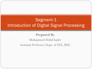
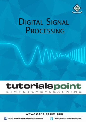
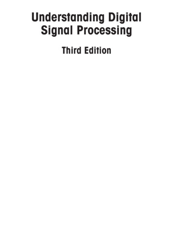
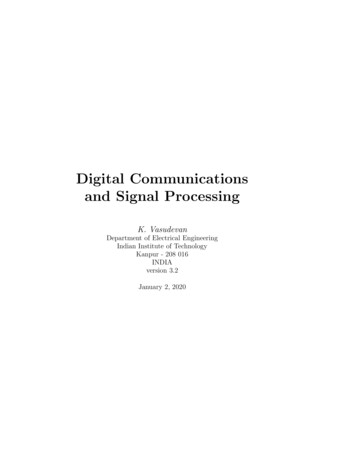
Micro-MeasurementsStrain Gages and InstrumentsTech Note TN-517Introduction to Digital Signal Processing1.0 IntroductionSampling rate: 1000/sWhen a signal varies with time, we are usually concernednot only with its magnitude but also with how it changes.Oscilloscopes, strip chart recorders and other analogrecording devices enable us to make observations ofthe signal by continuously recording and displaying themeasurement data in the time domain. When digitalcomputers are utilized for this purpose, however, themagnitude of the signal is sampled only at fixed intervalsof time with a complete loss of continuity between. Fordata acquired in this form, the mathematics of digitalsignal processing can be used to analyze the signal in boththe time and frequency domains. That is, we can know notonly how the magnitude of the signal varied with time, butalso what the amplitudes of any oscillations were over aspectrum of frequencies.This Tech Note is intended as a guide to understanding thenecessary considerations for converting an analog signalinto a useful series of discrete digital data, particularly asrelated to StrainSmart Data Systems.*ScansFrequency: 1000 Hz*01**23Time, msFigure 1Sampling rate: 1333/sFrequency: 1000 Hz2.0 Signal Aliasing2.1 FundamentalsCare must be taken when dealing with digital data toavoid the creation of false, lower-frequency signals by aphenomenon called aliasing. Do you remember seeing thespoke wheels of a wagon that appeared to turn backwardsas the wagon rolled across a television or movie screen?That’s a false visual impression caused by aliasing. Whenthe wheel is rotating at a slightly slower rate than that atwhich the frames are projected, the wheels appear to runin reverse. Further, if the wheels were rotated at the samerate as the frames are projected, the wheel would appear tobe static, or not turning at all!All sampling between 1000 and 2000 times per secondwould produce a lower-frequency alias. Shown here is the333-Hz alias that we would “see” at a sample rate of 1333per second (Figure 2).Document Number: 11067Revision: 01-Nov-2010Scans0***1.5Time, ms*3.0Figure 2Sampling at 2000 times per second, the signal would againappear to be static (Figure 3).So what is it that we must do to ensure that our instrumentalways sees the wagon wheel turning in the right direction?The answer is to always sample at more than twice thehighest rate of oscillation. When sampling at 4000 timesa second (Figure 4), we can see that it is impossible toproduce either a static or lower-frequency alias from themeasurements.For technical support, asurements.com169Tech NoteSimilar things can happen with an analog signal thatis sampled periodically. Consider a sinusoidal signaloscillating at, say, 1000 Hz, or 1000 times per second. Ifwe sample this signal at the same rate as the oscillations(Figure 1), we might think the signal was static, not varyingwith time.*
TN-517Micro-MeasurementsIntroduction to Digital Signal ProcessingSampling rate: 2000/s* Scans **01Frequency: 1000 Hz***2*3.0 Digital Filters3The sampling rate of the ADC is typically much higher thanthat required to extract the necessary information from thesignal within the frequency range of interest. In addition toallowing unwanted higher frequency components (noise)to remain in the data, these higher sampling rates will alsoincrease data storage requirements and analysis time.Time, msFigure 3Sampling rate: 4000/sprevented, it is necessary to remove all components ofthe signal and noise with frequencies of half or more thesampling rate with a low-pass anti-aliasing filter. This is ananalog circuit through which the input signal must pass onits way to the analog-to-digital converter. Of course, thefilter not only eliminates any aliasing in the digital data,but also attenuates any true signals — wanted or unwanted— above the stopband of the filter. Thus, when the data issubsequently analyzed with digital signal processing, weneed not worry about any false lower-frequency signalsbeing left in the data by the analog-to-digital conversionprocess.Frequency: 1000 HzIn preparation for acquiring data in digital form, theanalog signal being measured is typically passed throughan analog filter to ensure that all components of the signal,and noise with frequencies corresponding to a half, ormore, of the digital sampling rate of the analog-to-digitalconverter (ADC), are removed. As described in Section2.0, this helps ensure that false lower-frequency signals —called aliases — are not introduced into the digital data bythe sampling process itself.Scans*0* ** * * ** * * *12**3Time, msTech NoteFigure 4Just how fast should we sample? The mathematics usedin digital signal processing can construct a model of theanalog waveform that produced a particular set of databy looking at how the magnitudes of the measurementsdata vary over time. For frequency domain analysis, thesampling rate can be quite close to twice the maximumrate of oscillation. Reconstruction of the actual signalitself would require a sampling rate of ten or more timesthe highest frequency.2.2 Anti-aliasing FiltersIn the general case, we do not know the frequency of anyof the oscillations that might be present in the signal beingmeasured. But, as was just shown, we do know thoseof half or more the sampling rate will produce aliasesduring acquisition. Therefore, to ensure that aliases arewww.micro-measurements.com170In order to acquire data at a lower rate while avoidingaliasing errors, it would be necessary to make physicalchanges to the analog anti-aliasing filter and slow downthe sampling rate of the ADC. The disadvantage ofthis approach is that different analog filter componentsare required for each sampling rate. A more practicalsolution is to leave the analog filter and ADC sampling rateunchanged and to mathematically eliminate any unwantedcomponents from the measured signal by passing thedigital data through a digital filter.Specifically, low-pass digital filters enable the digitaldata coming from the ADC to be “decimated.” Insteadof the software processing and storing data from everyanalog-to-digital conversion, the digital filter allows datato be sampled at intervals corresponding to every n thconversion, effectively reducing the sampling rate withoutintroducing aliases. And, at the same time, any unwantedhigher frequency components of the measured signal areeliminated from the digital data as well.Like an analog filter, the digital filter is selected on thebasis of which frequencies in the signal are to be retainedand which are to be rejected. Low-pass filters, the mostcommon type, are designed to allow signal componentsFor technical questions, contactmicro-measurements@vishaypg.comDocument Number: 11067Revision: 01-Nov-2010
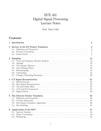
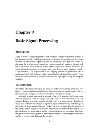
TN-517Micro-MeasurementsIntroduction to Digital Signal ProcessingPassbandRippleAttenuation, enuation0TransitionBandPassbandDigital FilterStopband0CutoffFrequencyAnalog Filter100FrequencyFigure 5When using digital filters, the user should pay attention toboth the stopband and the transition band. In some cases,particularly those with lower passband frequencies, theDocument Number: 11067Revision: 01-Nov-2010transition band may be as great as, or even greater than,the passband itself.Further, as shown in Figure 5, it should be noted that thepassband and stopband frequencies of digital filters differfrom the cutoff frequency of the commonly used Besseland Butterworth analog filters. The cutoff frequency of ananalog filter, typically specified at an attenuation of 3 dB,usually lies in the transition band between the passbandand stopband frequencies of com parable digital filters.Digital filters are a combination of mathematical algorithms and fast digital circuits that operate on a series ofdigital data acquired over a period of time. The necessityof using a series of data leads to a delay as the data passesFor technical questions, asurements.com171Tech Notefrom 0 Hz (dc) to some nonzero passband frequency, fo,to pass essentially un a ltered (Figure 5). The filter doesintroduce a series of small positive and negative deviationsfrom the actual signal in the passband. When this “ripple”exceeds a certain amount, typically 0.01 dB, it defines thepassband frequency. For frequencies in the transition bandbetween the passband frequency and higher stopbandfrequency, the signal is increasingly attenuated. When theattenuation reaches a certain level, typically in the vicinityof 95 dB, it defines the stopband frequency of the digitalfilter.
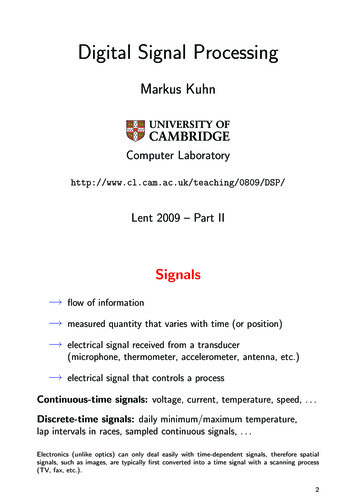
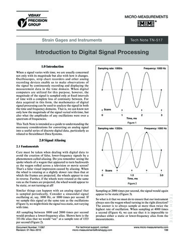
TN-517Micro-MeasurementsIntroduction to Digital Signal Processingthrough the filter. After each new sample is taken, the oldestdata drops off the front of the series, the remaining data ismoved forward in the series, and the data just acquiredis added to the end of the series. Then the algorithm isapplied to the series of data to obtain a calculated valuefor the filtered data. The delay, calculated as the time aparticular sample takes to get midway through the series,is a function of the ADC sampling rate, the number ofterms used in the series, and the passband frequency.Accordingly, the same digital filter should be selected forall measurement channels to ensure that all data acquiredat the same time emerges from the digital filters at thesame, but delayed, time.4.0 Throughput Rates of Digital SystemsThe electrical resistance strain gage is an inherentlyanalog device that utilizes changes in the relative resistanceof the gage to quantify mechanical strains in the surface towhich it is attached. Of course, as readers probably alreadyknow, the strain gage is typically connected to someform of instrumentation that incorporates a Wheatstonebridge circuit to provide an analog electrical signal thatvaries as the strain changes. Indeed, most sensors —whether they be strain-gage-based transducers, LVDTs,thermocouples, piezoelectric devices, or a wide variety ofothers — ultimately produce such a signal.Tech NoteUnfortunately, the digital computers increasinglyincorporated into measurement systems are inherentlyincompatible w ith these analog sig nals. To storemeasurement data in digital form, the analog signal mustbe sampled at various points in time and converted tonumbers, i.e., the signal must be digitized. Ideally, the timebetween samples should be vanishingly small (approachingzero). But we know from arithmetic that anything dividedby zero is infinitely large. And, of course, the computer canhandle only a finite number of data points. The questionthen becomes how infrequently to sample. If the signal isoscillating on a regular basis, then a minimum of ten datapoints per period, for the highest frequency component toreasonably reconstruct the signal in the time domain, aretypically required. In the frequency domain, any rate ofmore than two samples per period will suffice. In order forthese conditions to be met, a digital measurement systemmust have a sufficient throughput rate.such things as (1) the need for oversampling to eliminatealiasing in dynamic signals, (2) the presence of bottlenecksin the communications link between instrumentation andcomputer hardware, and (3) limitations in the rate at whichsoftware can acquire, reduce, store, and/or present thedigital data.A calculation of throughput also requires knowledge ofhow the instrumentation hardware acquires the data. Thesimplest approach is to sequentially sample each datachannel in the system at fixed intervals (Figure 6). System4000, the original Micro-Measure m ents data system,acquires data in this fashion, using a single ADC at athroughput rate of 25 or 30 samples per second (dependingupon the frequency of the mains ure 6A more complicated approach, at the opposite end of thespectrum, is to simultaneously sample each data channel inthe system (Figure 7). System 6000 does this at rates of up to10 000 samples per second per channel. Because a separateADC is used for each instrumentation card, the theoreticalthroughput rate of the system is 10 000 times the numberof channels used in the system. For a 100 channel system,that would be a million samples per second. However,because of the limitations in the digital communicationslink between instrumentation hardware (where the datais ac quired) and computer (where the data is stored), thepractical maximum throughput of System 6000 utilizingModel 6100 Scanners is about 200 000 samples per secondper system for data acquisition and storage. That total canbe from a combination of 20 channels acquiring data at10 000 samples a second, or of 1000 channels acquiring 200samples a second.SignalsIn the simplest of terms, the throughput rate is little morethan an indication of how much digital data a specificcombination of hardware and software can acquire perunit of time. At the instrumentation level, it is primarilycontrolled by the number of analog-to-digital converters(ADCs) being used in the system, and the rate at which theanalog signals being measured can be sampled and digitized.The useful throughput rate of the overall data acquisitionsystem, however, is typically much slower because ofwww.micro-measurements.com172ScannerSignalFor technical questions, s samplingFigure 7Document Number: 11067Revision: 01-Nov-2010
TN-517Micro-MeasurementsIntroduction to Digital Signal ProcessingA substantially higher throughput can be obtained withSystem 7000 (or System 6000 using the Model 6200Scanners), which simultaneously sample and store datalocally on each scanner (Figure 8). With a full complementof sixteen cards, each System 7000 scanner has a practicalthroughput of 256 000 samples per second (128 channels at2000 samples/second/channel) or 160 000 samples/second(16 channels at 1
in digital signal processing can construct a model of the analog waveform that produced a particular set of data by looking at how the magnitudes of the measurements data vary over time. For frequency domain analysis, the sampling rate can be quite close to twice the maximum rate of oscillation. Reconstruction of the actual signal itself would require a sampling rate of ten or more times the .