Transcription
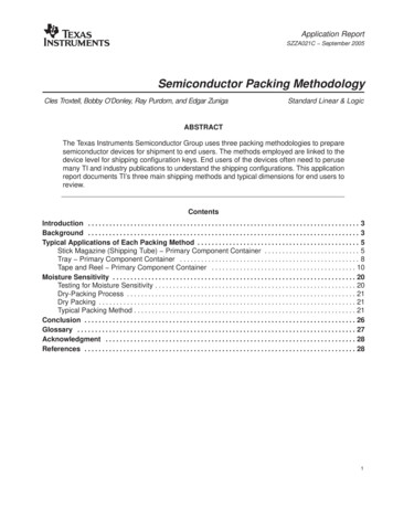
Accepted by EIASFF-8482 Rev 2.4SFF CommitteeSFF-8482Specification forSerial Attachment 2X Unshielded ConnectorEXPIREDStandardized by EIA at Rev 2.2 dated February 1 2006This specification was submitted as a project to the Electronic IndustriesAlliance, and has Expired because it became an EIA standard.If there were modifications subsequent to the date of submittal, or any were madeduring the EIA approvals process, they are not reflected in this copy.EIA standards can be purchased from http://global.ihs.com/As of May 2015:EIA-677Small Form Factor Power Connector Pin DimensionsEIA-720Small Form Factor 63.5mm (2.5") Disk DrivesEIA-740Small Form Factor 88.9mm (3.5") Disk DrivesEIA-741Small Form Factor 133.35mm (5.25") Disk DrivesEIA-964QSFP 4X 10 Gb/s Pluggable TransceiverEIA-965Mini Multilane 12 Gbs 12X ShieldedEIA-966Serial Attachment 2X UnshieldedEIA-967Micro Serial Attachment 3 Gbs 4X UnshieldedEIA-974Mini Multilane 4X 10 Gb/s Common Elements ConnectorEIA-975Mini Multilane 4X Unshielded Connector Shell and PlugEIA-976Mini Multilane 4X Shielded Connector Shell and bsequent to adoption by EIA, this specification has been revisedThe editor had cause to generate a new revision to include content added to supporthigher speeds. The details are reflected in the Update History.Until these changes have been adopted by the EIA, this specification represents thelatest information.Serial Attachment 2X Unshielded ConnectorPage 1
Accepted by EIASFF-8482 Rev 2.4SFF Committee documentation may be purchased in electronic form.SFF specifications are available at ftp://ftp.seagate.com/sffSFF CommitteeSFF-8482Specification forSerial Attachment 2X Unshielded ConnectorRev 2.4Secretariat:May 8, 2015SFF CommitteeAbstract: This specification defines an Unshielded dual lane Input/Outputconnector for serial interface unshielded devices, backplanes and cables.There are multiple using generations based on performance.3 Gb/s12 Gb/s24 Gb/sSFF-8678SFF-8680SFF-8681This specification provides a common reference for systems manufacturers, systemintegrators, and suppliers. This is an internal working specification of the SFFCommittee, an industry ad hoc group.This specification is made available for public review, and written comments aresolicited from readers. Comments received by the members will be considered forinclusion in future revisions of this specification.The description of a connector in this specification does not assure that thespecific component is actually available from connector suppliers. If such aconnector is supplied it must comply with this specification to achieveinteroperability between suppliers.Support: This specification is supported by the identified member companies of theSFF Committee.POINTS OF CONTACT:Jay NeerIndustry Standards ManagerMolex2222 Wellington CourtLisle, Il 60532I. Dal AllanChairman SFF Committee14426 Black Walnut CourtSaratoga, CA lcom@acm.orgSerial Attachment 2X Unshielded ConnectorPage 2
Accepted by EIASFF-8482 Rev 2.4EXPRESSION OF SUPPORT BY MANUFACTURERSThe following member companies of the SFF Committee voted in favor of this industryspecification.AdaptecAmphenolComaxDellDell ComputerEMCENDLFCIFoxconnFujitsu CPAHewlett PackardHGSTHitachi CableHitachi GSTIBMIntelLSIMGEMolexNetAppSandiskSeagateSun MicrosystemsTE ConnectivityUnisysVolexWestern DigitalThe following SFF member companies voted no on the technical content of thisindustry specification.All Best TechniqueThe following member companies of the SFF Committee voted to abstain on thisindustry nFinisarFoxconnFujitsu ComponentsInfineonLSILuxshare-ICTMadison erSumitomoToshibaToshiba AmericaTriQuintVitesse SemiconductorXyratexThe user's attention is called to the possibility that implementation to thisSpecification may require use of an invention covered by patent rights. Bydistribution of this specification, no position is taken with respect to thevalidity of a claim or claims or of any patent rights in connection therewith.Members of the SFF Committee which advise that a patent exists are required toprovide a statement of willingness to grant a license under these rights onreasonable and non-discriminatory terms and conditions to applicants desiring toobtain such a license.Serial Attachment 2X Unshielded ConnectorPage 3
Accepted by EIASFF-8482 Rev 2.4Change HistoryRevision 2.3- Edited out symbols because of reports that a few were not being displayed onscreen correctly by some PDF readers.- Clarified first and second stage content in 5.1 per request.Revision 2.4- p2 reflects support of SFF-8482 and SFF-8680- Body replaced by SFF-8680 mechanical content which had enhanced host board solderpads and attachment specifications.Previous history of SFF-8680:- Footprints of SFF-8482 and SFF-8680 defined as Appendixes- SFF-8680 1.5o Adopted common representation for SFF-8630/SFF-8639/SFF-8680Table 6-x Performance RequirementsAppendix A introductory paragraphs- SFF-8680 1.6o Corrected Abstract EIA-966 reference to be formerly SFF-8482- SFF-8680 1.7o Editorial update to auto-generate Appendix in headings and TOC.- SFF-8680 1.8o Added EIA reference for Temperature Rise in Electrical Requirements Table- SFF-8680 1.9o Added additional footprints to Appendix A1. Through-hole (Figure A-3)2. Hybrid (Figure A-4)Serial Attachment 2X Unshielded ConnectorPage 4
Accepted by EIASFF-8482 Rev 2.4ForewordThe development work on this specification was done by the SFF Committee, anindustry group. The membership of the committee since its formation in August 1990has included a mix of companies which are leaders across the industry.When 2 1/2" diameter disk drives were introduced, there was no commonality onexternal dimensions e.g. physical size, mounting locations, connector type, andconnector location, between vendors.The first use of these disk drives was in specific applications such as laptopportable computers and system integrators worked individually with vendors todevelop the packaging. The result was wide diversity, and incompatibility.The problems faced by integrators, device suppliers, and component suppliers led tothe formation of the SFF Committee as an industry ad hoc group to address themarketing and engineering considerations of the emerging new technology.During the development of the form factor definitions, other activities weresuggested because participants in the SFF Committee faced more problems than thephysical form factors of disk drives. In November 1992, the charter was expanded toaddress any issues of general interest and concern to the storage industry. The SFFCommittee became a forum for resolving industry issues that are either notaddressed by the standards process or need an immediate solution.Those companies which have agreed to support a specification are identified in thefirst pages of each SFF Specification. Industry consensus is not an essentialrequirement to publish an SFF Specification because it is recognized that in anemerging product area, there is room for more than one approach. By making thedocumentation on competing proposals available, an integrator can examine thealternatives available and select the product that is felt to be most suitable.SFF Committee meetings are held during T10 weeks (see www.t10.org), and SpecificSubject Working Groups are held at the convenience of the participants. Materialpresented at SFF Committee meetings becomes public domain, and there are norestrictions on the open mailing of material presented at committee meetings.Most of the specifications developed by the SFF Committee have either beenincorporated into standards or adopted as standards by EIA (Electronic IndustriesAssociation), ANSI (American National Standards Institute) and IEC (InternationalElectrotechnical Commission).If you are interested in participating or wish to follow the activities of the SFFCommittee, the signup for membership and/or documentation can be found at:www.sffcommittee.com/ie/join.htmlThe complete list of SFF Specifications which have been completed or are currentlybeing worked on by the SFF Committee can be found at:ftp://ftp.seagate.com/sff/SFF-8000.TXTIf you wish to know more about the SFF Committee, the principles which guide theactivities can be found ns for improvement of this specification will be welcome. They should besent to the SFF Committee, 14426 Black Walnut Ct, Saratoga, CA 95070.Serial Attachment 2X Unshielded ConnectorPage 5
Accepted by EIASFF-8482 Rev 2.4CONTENTS1.Scope1.1Application Specific Criteria772.References2.1Industry Documents2.2SFF ns7777783.General Description94.Dimensioning Requirements4.1Connector Interface4.2General Tolerances1010105.Backplane Fixed (Receptacle) Interface Features5.1Blind Mating5.2Device to Backplane Location5.3Hot 020207.General Connector Performance Requirements20A.Appendix (Informative): Receptacle PCB Footprints (High Performance)22B.Appendix (Informative): Receptacle PCB gureFigureFigureFIGURESMating Side GenderGeneral ViewsDevice Free (Plug) ConnectorDevice Free (Plug) Connector Detail and Section ViewBackplane Fixed (Receptacle) ConnectorBackplane Fixed (Receptacle) Connector Section ViewCable Fixed (Receptacle) ConnectorBlind Mate Tolerance ZonesDevice to Backplane 11121314151717Printed Circuit Board Detail Surface MountPrinted Circuit Board Detail Alternate Surface MountPrinted Circuit Board Detail Through HolePrinted Circuit Board Detail HybridThrough Hole Printed Circuit Board Detail (Press Fit & Solder Pin)Surface Mount Printed Circuit Board DetailHybrid Printed Circuit Board -17-27-3Hot Plug Contact SequencingElectrical RequirementsMechanical RequirementsEnvironmental RequirementsSerial Attachment 2X Unshielded Connector19202121Page 6
Accepted by EIASFF-8482 Rev 2.4SFF Committee -Serial Attachment 2X Unshielded Connector1. ScopeThis specification defines the mechanical and connector contact performancerequirements for a composite connector system. This composite system is designed tosupport high speed serial signals and power on different contacts within the samehousing.1.1Application Specific CriteriaIntended applications for this connector system include Serial Attached SCSI (SAS)as specified by the T10 standards and for other applications requiring such aconnector system.2. References2.1Industry DocumentsThe following interface standards are relevant to this SFF Specification.- ASME Y14.5M- EIA-364-D-INCITS 478INCITS 519INCITS nsioning and TolerancingElectrical Connector/Socket Test Procedures Including EnvironmentalClassifications (see Section 7 for relevant test procedures)Serial Attached SCSI 2.1 (SAS-2.1)Serial Attached SCSI - 3 (SAS-3)Serial Attached SCSI - 4 (SAS-4)2.5 inch Form Factor Drive w/Serial Attached Connector (EIA-720)3.5 inch Form Factor Drive w/Serial Attached Connector (EIA-740)Serial Attachment 2X 3 Gb/s Unshielded ConnectorSerial Attachment 2X 12 Gb/s Unshielded ConnectorSerial Attachment 2X 24 Gb/s Unshielded ConnectorSFF SpecificationsThere are several projects active within the SFF Committee. The complete list ofspecifications which have been completed or are still being worked on are listed inthe specification at ose who join the SFF Committee as an Observer or Member receive electronic copiesof the minutes and SFF specifications (http://www.sffcommittee.com/ie/join.html).Copies of ANSI standards may be purchased from the InterNational Committee forInformation Technology Standards ventionsThe ISO convention of numbering is used i.e., the thousands and higher multiplesare separated by a space and a period is used as the decimal point. This isequivalent to the English/American convention of a comma and a period.American0.61,0001,323,462.9French0,61 0001 323 462,9Serial Attachment 2X Unshielded ConnectorISO0.61 0001 323 462.9Page 7
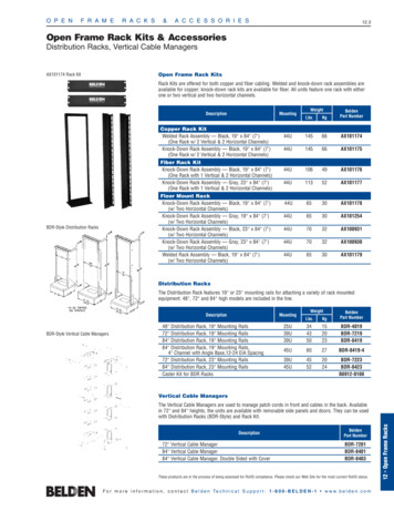
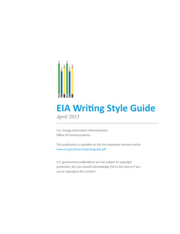
Accepted by EIA2.5SFF-8482 Rev 2.4DefinitionsFor the purpose of SFF Specifications, the following definitions apply:Fixed: Used to describe the gender of the mating side of the connector thataccepts its mate upon mating. This gender is frequently, but not always,associated with the common terminology "receptacle". Other terms commonly used are"female" and "socket connector". The term "fixed" is adopted from EIA standardterminology as the gender that most commonly exists on the fixed end of aconnection, for example, on the board or bulkhead side.In this specification "fixed" is specifically used to describe the mating sidegender illustrated in Figure 3-1 as Backplane "Fixed" (receptacle)and Cable "Fixed"(receptacle).Fixed Board: A connector that uses a fixed gender mating side and a terminationside suitable for any of the printed circuit board termination technologiesFree: Used to describe the gender of the mating side of the connector thatpenetrates its mate upon mating. This gender is frequently, but not always,associated with the common terminology "plug". Other terms commonly used are"male" and "pin connector". The term "free" is adopted from EIA standardterminology as the gender that most commonly exists on the free end of aconnection, for example, on the cable side.In this specification "free" is specifically used to describe the mating sidegender illustrated in Figure 3-1 as Device "Free" (plug).Free Board: A connector that uses a free gender mating side and a termination sidesuitable for any of the printed circuit board termination technologiesMating side: The side of the connector that joins and separates from the matingside of a connector of opposite gender. Other terms commonly used in the industryare mating interface, separable interface and mating face.FIGURE 2-1 MATING SIDE GENDERSerial Attachment 2X Unshielded ConnectorPage 8
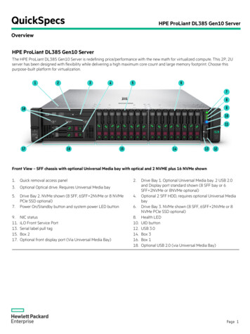
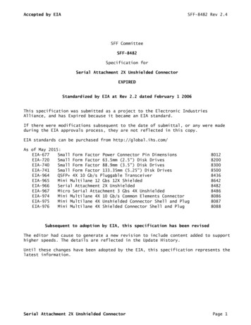
Accepted by EIASFF-8482 Rev 2.43. General DescriptionThis connector system is designed to allow devices to connect to cable assembliesor to PCB's with the same device connector interface.The device free (plug) interface incorporates three different contact sets (CS).Two of these sets (CS1 and CS2) contain 7 contacts each and typically are used forhigh speed serial signals. The high speed signals are grouped into differentialpairs flanked with Grounds (G-S-S-G-S-S-G). The third set (CS3) contains 15contacts and typically would be used for low frequency purposes such as power andcontrol.The backplane fixed (receptacle) interface supports device free (plug) interfaceswhich have CS1 and CS3 only or has all CS1, CS2 and CS3 contacts. Blind mating issupported by the guides built into the mating interface and a provision for hotplugging is supported by the contact sequencing that is possible by using theoffset contact positions.There is no provision for positive mating interface retention latching in thebackplane fixed version.FIGURE 3-1 GENERAL VIEWSThe cable fixed (receptacle) supports device free (plug) interfaces which have CS1and CS3 only or has all CS1, CS2 and CS3 contacts. The cable fixed (receptacle)interface incorporates a passive latching retention system to prevent accidentaldisconnection of the interface.For cabled backplane implementation, the cable connector shall provide all featureSerial Attachment 2X Unshielded ConnectorPage 9
Accepted by EIASFF-8482 Rev 2.4requirements of the backplane fixed (receptacle)in addition to the passive cableretention defined.4.4.1Dimensioning RequirementsConnector InterfaceAll dimensional requirements for the connector within this specification must bemet in order to provide intermateability between plug and receptacle and to fitwithin the physical boundaries required by the media and backplane.4.2General TolerancesUnless otherwise shown, the following tolerances apply to the figures:2 Place dimension /-0.20mmAngular dimension /-3 degreesThe range of characteristics supported is indicative of the environment of use.Serial Attachment 2X Unshielded ConnectorPage 10
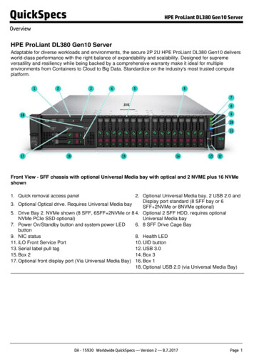
Accepted by EIASFF-8482 Rev 2.4FIGURE 4-1 DEVICE FREE (PLUG) CONNECTORSerial Attachment 2X Unshielded ConnectorPage 11
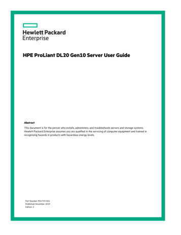
Accepted by EIASFF-8482 Rev 2.4FIGURE 4-2 DEVICE FREE (PLUG) CONNECTOR DETAIL AND SECTION VIEWSerial Attachment 2X Unshielded ConnectorPage 12
Accepted by EIASFF-8482 Rev 2.4FIGURE 4-3 BACKPLANE FIXED (RECEPTACLE) CONNECTORSerial Attachment 2X Unshielded ConnectorPage 13
Accepted by EIASFF-8482 Rev 2.4FIGURE 4-4 BACKPLANE FIXED (RECEPTACLE) CONNECTOR SECTION VIEWSerial Attachment 2X Unshielded ConnectorPage 14
Accepted by EIASFF-8482 Rev 2.4FIGURE 4-5 CABLE FIXED (RECEPTACLE) CONNECTORSerial Attachment 2X Unshielded ConnectorPage 15
Accepted by EIASFF-8482 Rev 2.45. Backplane Fixed (Receptacle) Interface Features5.1Blind MatingThe process of mating an unshielded serial attachment connector pair should beaccomplished in a "free fit" manner where no excessive mechanical stresses areplaced on the connectors during or after the mating process. The mating processshould be considered in the context of the packaging surrounding the device withthe connectors. Stresses considered include those transmitted to the matedconnector through the device: for example, the weight of the drive, that resultingfrom resilient device guide members in the enclosure, the device retentionmechanism, acceleration stresses (mechanical shock testing) and interference withenclosure parts. Mechanical interference between the device with the matedconnectors and fixed or solid parts of the packaging will generally not betolerated by the unshielded serial connector attachment system.The mating interface specifications require a two stage process to arrive at theFinal mated contact:- The first stage must be delivered by the device enclosure system to achievecenter to center alignment of less than 1.5 mm in the longitudinal axis and lessthan 1.0 mm in the horizontal axis prior to any part of the connector pairengaging. This is the blind mate tolerance zone depicted in Figure 5-1.- The second stage (incorporated within connector blind mate pre-alignmentfeatures) positions the connectors from /-1.5 mm / /-1.0 mm at initial engagementthrough to a point where the main connector chamfers engage (normal connectorengagement)System/Application designers should recognize that certain lateral movement betweenfree gender contacts and fixed gender contacts may occur between the time the prealignment features engage and the contacts reach the final mated position.The positional requirements in Figure 5-2 define the fully mated condition.CAUTION: When mating unshielded serial attachment connectors without the aid ofguide rails (or other pre-mating guiding systems not part of the connector) thereis a risk of shorting signals to power. This event may damage the devices on eitherside of the connector.Serial Attachment 2X Unshielded ConnectorPage 16
Accepted by EIASFF-8482 Rev 2.4FIGURE 5-1 BLIND MATE TOLERANCE ZONES5.2Device to Backplane LocationIn order to guarantee minimum contact engagement is provided in a backplane system,the position of the device connector interface must be controlled relative to theBackplane surface as shown in Figure 5-2.Device clearances vary by Form Factor, see the appropriate Form FactorSpecifications for connector location with respect to each Form Factor.FIGURE 5-2 DEVICE TO BACKPLANE LOCATIONSerial Attachment 2X Unshielded ConnectorPage 17
Accepted by EIA5.3SFF-8482 Rev 2.4Hot PluggingIn order to facilitate hot plugging of a device into a powered backplane, theBackplane fixed (Receptacle) & Device free (plug) interface is designed to providea 3 level contact engagement sequence. By specifying an offset between key contactson each side of the mating interface, the mating sequence of these contacts istimed to occur in the proper order. There are 2 pins located in CS3 of theBackplane fixed (receptacle) interface that are advanced 0.50mm nominal from allother contact pins on this side of the interface. These pin locations represent the1st level of mating upon insertion of the Device. The 2nd level of mating isestablished when the forward group of contacts located in the CSs of the Devicefree (plug) interface penetrate 0.50mm nominal into the Backplane fixed(receptacle) interface. The remaining contacts of the Device free (plug) interfaceare set back 0.50mm nominal and will be the last contacts to mate. In order tomaintain this sequence, sufficient tolerance has been designed into the interfaceto allow for manufacturing and alignment of the device to the enclosure – seesection 5.1.The pin locations for the long & short contacts on both sides of the interface aredefined in Table 5-1.Hot plugging of cables is not supported by this interface.Serial Attachment 2X Unshielded ConnectorPage 18
Accepted by EIASFF-8482 Rev 2.4TABLE 5-1 HOT PLUG CONTACT SEQUENCINGDevice Free (Plug) InterfaceBackplane Fixed (Receptacle) 7P7P8P8P9P9P10P10P11P11P12P12P13P13P14P14P15P15 -0.50mm- Serial Attachment 2X Unshielded Connector -0.50mm- Page 19
Accepted by EIASFF-8482 Rev 2.46. Ratings6.1CurrentPower section (per pin):- Continuous Current 1.5 A- Peak Current 2.5A 1.5 s- Peak Current Pre-charge 6A 1 msSignal section (per pin)- Continuous Current 500 mA6.2TemperatureOperatingNon-operating0 C to 55 C-40 C to 85 C7. General Connector Performance RequirementsThe General Electrical, Mechanical and Environmental requirements for matingconnectors are listed in the tables.See section 1.2 for the Electrical Performance requirements for this connectorsolution.TABLE 7-1 ELECTRICAL REQUIREMENTSDescriptionRequirementLow LevelContactResistanceInsulationResistance30 milliohmsmaximum for signalcontacts (initial)1000 atureRise (viacurrentcycling) Powersection only(P1 thru P15)No breakdown orflashoverTemperature riseshall not exceed30C degreesProcedureEIA-364-23:Mate connectors and apply a maximum voltageof 20 mV and a current of 100 mAEIA 364-21:Apply a voltage of 500 VDC for 1 minutebetween adjacent terminalsEIA 364-20, method B:Apply a voltage of 500 VAC for 1 minutebetween adjacent terminalsEIA-364-70B:Wire contact pins P1, P2, P8 and P9 inparallel for powerWire contact pins P4, P5, P6, P10 and P12 inparallel for returnSupply 6 Amp total DC current to the powerpins in parallel, returning from the parallelground pinsMeasure and record the temperature after 96hours (45 minutes ON and 15 minutes OFF perhour) in ambient condition of 25C still airSerial Attachment 2X Unshielded ConnectorPage 20
Accepted by EIASFF-8482 Rev 2.4TABLE 7-2 MECHANICAL ionDurabilityConnector Mateand UnmateForcesRequirementDiscontinuity 1microsecond 15milliohm maximumchange from initialContact ResistanceDiscontinuity 1microsecond15 milliohm maximumchange from initialContact ResistanceNo damage15 milliohm maximumchange from initialContact ResistanceBackplaneMate- 25N maxUnmate - 5N minCableMate- 50N maxUnmate - 20N minInitial and afterdurabilityProcedureEIA-364-27Subject mated connectors to 50G’s half-sineshock pulses of 11 milliseconds duration ineach X,Y and Z axis (18 shocks total)EIA-364-28, Test Condition VIISubject mated connectors to 3.10G’s RMSbetween 20-500 Hz for 15 minutes in each of 3mutually perpendicular planesEIA 364-09:Mate and unmate connectors at a maximum rateof 200 cycles per hourBackplane - 500 CyclesCable- 25 CyclesEIA 364-13:Mate and unmate connectors at a rate of 25mmper minuteTABLE 7-3 ENVIRONMENTAL MixedFlowing GasHumidityRequirementNo damage15 milliohm maximumchange from initialContact ResistanceNo damage15 milliohm maximumchange from initialContact ResistanceNo damage15 milliohm maximumchange from initialContact ResistanceNo damage15 milliohm maximumchange from initialContact ResistanceProcedureEIA 364-32, Test Condition I:Subject mated connectors to 10 cycles betweenminus 55C and plus 85C degreesEIA 364-17, Test Condition III, Method A,Test Time Condition C:Subject mated connectors to 85C for 500 hoursEIA 364-65, Class IIA: (4 Gas)Expose half of samples unmated for 7 days andthen mated for 7 days. The other half areexposed mated for full 14 day test period.EIA 364-31, Method II, Test Condition A:Subject mated connectors to 96 hours at 40Cdegrees with 90-95% relative humidity perSerial Attachment 2X Unshielded ConnectorPage 21
Accepted by EIAA.SFF-8482 Rev 2.4Appendix (Informative): Receptacle PCB Footprints (High Performance)The PCB footprint has an impact on the Signal Integrity (SI) performance of theconnector system and the actual geometry may vary between different vendorimplementations. Being an example, the footprint may not meet the necessary SIperformance for all vendor implementations, and it is not a requirement of thisspecification.Note: This specification does not address the electrical performancecharacteristics of the host Printed Circuit Board (PCB) material and constructionused in these applications. The PCB thickness, number of layers, layer stack up,trace layer location(s), copper plane anti-pads, etc., as all are majorcontributors to the final electrical characteristics of each unique application ofthe connector.FIGURE A-1 PRINTED CIRCUIT BOARD DETAIL SURFACE MOUNTFIGURE A-2 PRINTED CIRCUIT BOARD DETAIL ALTERNATE SURFACE MOUNTSerial Attachment 2X Unshielded ConnectorPage 22
Accepted by EIASFF-8482 Rev 2.4FIGURE A-3 PRINTED CIRCUIT BOARD DETAIL THROUGH HOLE(Press Fit & Solder Pin)FIGURE A-4 PRINTED CIRCUIT BOARD DETAIL HYBRIDSerial Attachment 2X Unshielded ConnectorPage 23
Accepted by EIAB.SFF-8482 Rev 2.4Appendix (Informative): Receptacle PCB FootprintsThese footprint examples suit the performance defined by SFF-8678.FIGURE B-1 THROUGH HOLE PRINTED CIRCUIT BOARD DETAIL (PRESS FIT & SOLDER PIN)FIGURE B-2 SURFACE MOUNT PRINTED CIRCUIT BOARD DETAILPad widths listed as reference dimensions are left open to the manufacturer todetermine based on their internal design standards. In order to determine the padwidths for Surface Mount leads the following dimensions and tolerances apply:Solder Leads on 1.27mm spacing 0.40 /- 0.08mmSolder Leads on 0.80mm spacing 0.30 /- 0.05mmSerial Attachment 2X Unshielded ConnectorPage 24
Accepted by EIASFF-8482 Rev 2.4FIGURE B-3 HYBRID PRINTED CIRCUIT BOARD DETAILHole sizes listed as reference dimensions are left open to the manufacturer todetermine based on their internal design standards. In order to determine the holediameter for Solder Pins the following pin width dimensions and tolerances apply:Solder Pins on 1.27mm spacing 0.40 /- 0.08mmSolder Pins on 0.80mm spacing 0.40 /- 0.08mmPad widths listed as reference dimensions are left open to the manufacturer todetermine based on their internal design standards. In order to determine the padwidths for Surface Mount leads the following dimensions and tolerances apply:Solder Leads on 1.27mm spacing 0.40 /- 0.08mmSolder Leads on 0.80mm spacing 0.30 /- 0.05mmSerial Attachment 2X Unshielded ConnectorPage 25
Serial Attachment 2X Unshielded Connector Page 1 SFF Committee SFF-8482 Specification for Serial Attachment 2X Unshielded Connector EXPIRED Standardized by EIA at Rev 2.2 dated February 1 2006 This specification was submitted as a project to the Electronic Industries Alliance, and has Expired because it became an EIA standard.