Transcription
PublishedSFF-8083 Rev 2.5SFF Committee documentation may be purchased in hard copy or electronic form.SFF specifications are available at ftp://ftp.seagate.com/sffSFF CommitteeSFF-8083 Specificationfor0.8mm Card Edge Connector for 8/10 Gbs ApplicationsRev 2.5January 19 2010Secretariat: SFF CommitteeAbstract: This specification defines the physical interface and general performancerequirements of the mating interface for an improved 0.8mm card edge connector foruse in applications up to approximately 10 Gbit/s using the upper row of contacts.One such use is as the receptacle connector for the SFF-8432 Improved PluggableFormfactor when used with SFF-8431 Enhanced 8.5 and 10 Gigabit SFF Pluggable Moduleaka SFP .This specification provides a common reference for systems manufacturers, systemintegrators, and suppliers. This is an internal working specification of the SFFCommittee, an industry ad hoc group.This specification is made available for public review, and written comments aresolicited from readers. Comments received by the members will be considered forinclusion in future revisions of this document.The description of a connector in this specification does not assure that thespecific component is actually available from connector suppliers. If such aconnector is supplied it must comply with this specification to achieveinteroperability between suppliers.Support: This specification is supported by the identified member companies of theSFF Committee.Points of Contact:Jay NeerMolex2222 Wellington CourtLisle, Il 60532I. Dal AllanChairman SFF Committee14426 Black Walnut CourtSaratoga, CA 95070561-447-2907x3889jay.neer at molex dot com408-867-6630endlcom at acm dot org0.8mm Card Edge Connector for 8 Gbs ApplicationsPage 1
PublishedSFF-8083 Rev 2.5EXPRESSION OF SUPPORT BY MANUFACTURERSThe following member companies of the SFF Committee voted in favor of this Hewlett PackardHitachi GSTJDS UniphaseLuxteraPanduitSun MicrosystemsToshibaTycoVitesse SemiconductorThe following SFF member companies voted no on the technical content of thisindustry specification.AMCCAmphenolMolexThe following member companies of the SFF Committee voted to abstain on thisindustry specification.Arista NetworksAvagoCortina SystemsDell ComputerFoxconnFujitsu CPAICT eagateToshiba AmericaVolexThe user's attention is called to the possibility that implementation to thisSpecification may require use of an invention covered by patent rights. Bydistribution of this Specification, no position is taken with respect to thevalidity of this claim or of any patent rights in connection therewith. Members ofthe SFF Committee, which advise that a patent exists, are required to provide astatement of willingness to grant a license under these rights on reasonable andnon-discriminatory terms and conditions to applicants desiring to obtain such alicense.0.8mm Card Edge Connector for 8 Gbs ApplicationsPage 2
PublishedSFF-8083 Rev 2.5Foreword:The development work on this specification was done by the SFF Committee, anindustry group. The membership of the committee since its formation in August 1990has included a mix of companies which are leaders across the industry.When 2 1/2” diameter disk drives were introduced, there was no commonality onexternal dimensions e.g. physical size, mounting locations, connector type,connector location, between vendors.The first use of these disk drives was in specific applications such as laptopportable computers and system integrators worked individually with vendors todevelop the packaging. The result was wide diversity, and incompatibility.The problems faced by integrators, device suppliers, and component suppliers led tothe formation of the SFF Committee as an industry ad hoc group to address themarketing and engineering considerations of the emerging new technology.During the development of the form factor definitions, other activities weresuggested because participants in the SFF Committee faced more problems than thephysical form factors of disk drives. In November 1992, the charter was expanded toaddress any issues of general interest and concern to the storage industry. The SFFCommittee became a forum for resolving industry issues that are either not addressedby the standards process or need an immediate solution.Those companies which have agreed to support a specification are identified in thefirst pages of each SFF Specification. Industry consensus is not an essentialrequirement to publish an SFF Specification because it is recognized that in anemerging product area, there is room for more than one approach. By making thedocumentation on competing proposals available, an integrator can examine thealternatives available and select the product that is felt to be most suitable.SFF Committee meetings are held during T10 weeks (see www.t10.org), and SpecificSubject Working Groups are held at the convenience of the participants. Materialpresented at SFF Committee meetings becomes public domain, and there are norestrictions on the open mailing of material presented at committee meetings.Most of the specifications developed by the SFF Committee have either beenincorporated into standards or adopted as standards by EIA (Electronic IndustriesAssociation), ANSI (American National Standards Institute) and IEC (InternationalElectrotechnical Commission).If you are interested in participating or wish to follow the activities of the SFFCommittee, the signup for membership and/or documentation can be found at:www.sffcommittee.com/ie/join.htmlThe complete list of SFF Specifications which have been completed or are currentlybeing worked on by the SFF Committee can be found at:ftp://ftp.seagate.com/sff/SFF-8000.TXTIf you wish to know more about the SFF Committee, the principles which guide theactivities can be found at ftp://ftp.seagate.com/sff/SFF-8032.TXTSuggestions for improvement of this specification will be welcome. They should besent to the SFF Committee, 14426 Black Walnut Ct, Saratoga, CA 95070.0.8mm Card Edge Connector for 8 Gbs ApplicationsPage 3
PublishedSFF-8083 Rev 2.5Contents1Scope. 51.12Description of Clauses. 5References. 62.12.22.32.4Industry Documents.SFF Specifications.Sources.Conventions.66663General Description. 74Definitions and Abbreviations. 84.14.25Definitions. 8Abbreviations. 9Electrical Specifications. 105.15.26Electrical Requirements. 10High Frequency Performance Requirements. 10Mechanical Specifications. 126.16.26.36.47Connector Configurations.Mechanical Requirements.Contact Sequencing.Contact Numbering.12131315Connector Dimensions. 157.17.27.3Paddle Card. 16Board Side Connector. 18Board Side Connector Footprint. -16-27-17-27-3De-Embedding Reference Plane .General view of right-angled body receptacle .Contact sequencing .Paddle Card .Board Side Connector .Board Side Connector Footprint .111214161820Electrical Specifications and Test Conditions .Connector HIGH-Frequency PERFORMANCE REQUIREMENTS .Mechanical Requirements .Contact Numbering .Paddle Card .Board Side Connector .Board Side Connector Footprint leTable5-15-26-16-27-17-27-30.8mm Card Edge Connector for 8 Gbs ApplicationsPage 4
Published1SFF-8083 Rev 2.5ScopeThis specification defines the terminology and physical requirements for the matinginterface and physical characteristics of the improved 0.8 mm card edge connector.The dimensions specified apply to a family of connectors with 20, 30, 50 or 70contacts. It also defines electrical attributes that distinguish it from the SFF8084 0.8 mm card edge connector that defines a lower speed connector interface.Fibre Channel, 10G Ethernet, InfiniBand, other standards, and specifications such asSFP , define requirements on the characteristic impedance and ability to transmitmulti-gigabit signals to and from optical pluggable modules, and in some cases viacable assemblies. When this connector is used in such an application, it is subjectto the requirements of those documents.1.1Description of ClausesClause 1 contains the scope and purposeClause 2 contains referenced and related standards and SFF specificationsClause 3 contains the general descriptionClause 4 contains the definitions, abbreviations and conventionsClause 5 defines the electrical conditionsClause 6 defines the mechanical conditionsClause 7 defines the connector dimensions0.8mm Card Edge Connector for 8 Gbs ApplicationsPage 5
Published2SFF-8083 Rev 2.5ReferencesThe following interface standards and specifications are relevant to thisSpecification.2.1Industry DocumentsThe following standards and specifications are relevant to this Specification.ANSI/ASME Y14.5MEIA 364-06EIA 364-09EIA 364-13EIA 364-21INCITS 352:2002INCITS 404:200xT11/1625DT11/IEEE c Dimensioning and Tolerancing (GD&T)Contact Resistance Test Procedure For Electrical ConnectorsDurability Test Procedure For Electrical Connectors And ContactsMating And Unmating Forces Test Procedures For ElectricalConnectorsInsulation Resistance Test Procedure For Electrical ConnectorsSockets And Coaxial ContactsFC-PI (Fibre Channel Physical Interface)FC-PI-2 (Fibre Channel Physical Interface - 2FC-PI-3 (Fibre Channel Physical Interface - 3FC-PI-4 (Fibre Channel Physical Interface - 410 Gigabit Ethernet clause 5210GBASE-LRM clause 68Architecture Specification Volume 2SAS 1-1 (Serial Attached SCSI - 1.1)SFP (Small Formfactor Pluggable) TransceiverPCI Card Version of SFP Cage0.8mm Card Edge ConnectorHigh Speed Serial Testing for Copper LinksEnhanced 10 Gigabit Small Formfactor Pluggable Module (SFP )Improved Pluggable Formfactor (IPF)IPF (Improved Pluggable Formfactor) CageSFP Gerber FilesSFF SpecificationsThere are several projects active within the SFF Committee. The complete list ofspecifications which have been completed or are still being worked on are listed inthe specification at ose who join the SFF Committee as an Observer or Member receive electronic copiesof the minutes and SFF specifications (http://www.sffcommittee.com/ie/join.html).Copies of ANSI standards may be purchased from the InterNational Committee forInformation Technology Standards (http://tinyurl.com/c4psg).EIA documents are available at http://global.ihs.com802.3 Ethernet is available from http://standards.ieee.org/getieee802/802.3.htmlThe InfiniBand Architecture Specification Volume 2 is available sThe ISO convention of numbering is used i.e., the thousands and higher multiples areseparated by a space and a period is used as the decimal point. This is equivalentto the English/American convention of a comma and a period.0.8mm Card Edge Connector for 8 Gbs ApplicationsPage 6
PublishedSFF-8083 Rev 2.5English0.61,0001,323,462.93French0,61 0001 323 462,9ISO0.61 0001 323 462.9General DescriptionThe improved 0.8 mm connection system is based on industry-proven card edge stylecontacts, which mate with a single wipe, and are very difficult to damage.0.8 mm Card Edge connectors find their most important application where signals haverise times typically in the range of 35 ps and where positive retention is neededbut ease of insertion and removal is also desired. This covers virtually all of theexternal inter-enclosure applications for gigabit serial applications that usebalanced copper media for transmission.Design goals were minimization of crosstalk and minimum transmission line impedancediscontinuity across the connector interface at signaling rates up to 11.1 GBd onthe upper row of contacts. The lower row of contacts is rated at signaling rates upto 2.5 Gigabits/second.The shield (cage) contact (not shown or part of this specification) is required tomake contact before any of the signal contacts upon insertion and to break contactonly after all contacts are separated upon removal. This ensures that any groundpotential differences between enclosures are first exposed to the shield and therebyminimizes the risk of damaging the sensitive input and output stages of thetransceivers when the signal contacts are mated.A cage or latching device (not shown or part of this specification) is required toguide the mating interface (typically a paddle cad) into the connector, providesufficient wipe on the contact interface, provide a hard stop which prevents thetransceiver side from bottoming in the connector, and keeps the paddle card contactson the connector contacts during use.This connector is primarily used as a pluggable module connector but can also beused with direct attach cable assemblies.This specification includes the minimum lengths, widths and positional tolerances ofthe contacts.The connector is of a straightforward construction that does not rely on advancedmaterials or processes, and is physically robust.Connectors compliant to SFF-8083 are also compliant to SFF-8084, but the reverse isnot necessarily true.0.8mm Card Edge Connector for 8 Gbs ApplicationsPage 7
Published44.1SFF-8083 Rev 2.5Definitions and AbbreviationsDefinitionsFor the purpose of this specification, the following definitions apply:Advanced grounding contacts: Connector contacts that make first and break last andare capable of carrying power ground return currents and performing electrostaticdischarge. Other terms sometimes used to describe these features are: groundingpins, ESD contacts, grounding contacts, static drain, and pre-grounding contacts.Alignment guides: Connector features that preposition insulators prior toelectrical contact. Other terms sometimes used to describe these features are:guide pins, guide posts, blind mating features, mating features, alignment features,paddle card chamfers and mating guides.Centerline or CL: A real or imaginary line that is equidistant from the surface orsides of somethingContact mating sequence: Order of electrical contact during mating/unmatingprocess. Other terms sometimes used to describe this feature are: contactsequencing, contact positioning, make first/break last, EMLB (early make late break)staggered contacts, and long pin / short pin.Frontshell: That metallic part of a connector body that directly contacts thebackshell or other shielding material that provides mechanical and shieldingcontinuity between the connector and the cable. Other terms sometimes used todescribe this part of a cable assembly are: housing, nosepiece, cowling, and metalshroud.Maximum component height:module/connector feature.Distance from board surface to farthest overallMating side: The side of the connector that joins and separates from the matingside of a connector of opposite gender. Other terms commonly used in the industryare mating interface, separable interface and mating face.Offset: An alignment shift from the centerline of the connector. Connector contactsmay be offset from the CLOptional: This term describes features that are not required by this specification.However, if any feature defined by this specification is implemented, it shall bedone in the same way as defined by the specification. Describing a feature asoptional in the text is done to assist the reader. If there is a conflict betweentext and tables on a feature described as optional, the table shall be accepted asbeing correct.Right Angle: A connector design for use with printed circuit board assemblytechnology where the mating direction is parallel to the plane of the printedcircuit board.Surface mount: A connector design and a printed circuit board design style wherethe connector termination points do not penetrate the printed circuit board and aresubsequently soldered to the surface of the printed circuit board.Termination side: The side of the connector opposite the mating side that is usedfor permanently attaching conductors to the connector. Due to pin numberingdifferences between mating side genders the termination side shall always be0.8mm Card Edge Connector for 8 Gbs ApplicationsPage 8
PublishedSFF-8083 Rev 2.5specified in conjunction with a mating side of a specific gender. Other termscommonly used in the industry are: back end, non-mating side, footprint, pc boardside, and post side.Through-hole: A connector design and a printed circuit board design style where theconnector termination points penetrates the printed circuit board and aresubsequently soldered to the printed circuit board.4.2AbbreviationsCL:CenterlineMSA:Multiple source agreementPCB:Printed circuit boardSFP:Small Formfactor PluggableSFP : Enhanced 8.5 and 10 Gigabit Small Form Factor Pluggable ModuleSMT:Surface-mount technology0.8mm Card Edge Connector for 8 Gbs ApplicationsPage 9
Published55.1SFF-8083 Rev 2.5Electrical SpecificationsElectrical RequirementsThe electrical and low frequency performance requirements are defined inTABLE 5-1 ELECTRICAL SPECIFICATIONS AND TEST geLow level contactresistance with conductorresistance - InitialInsulation ResistanceDielectric withstandingvoltage5.2SpecificationsTest Conditions-20ºC to 85ºC80% RH Maximum0.5 A/contact30 V AC/contact20 milliOhm max change frominitial1e3 MegaOhm Minimum betweenadjacent contactsNo defect between adjacentcontactsEIA 364-6: 320 mV DC, 10 mAEIA 364-21: 100 V DC300 V DC for 1 minute holdHigh Frequency Performance RequirementsThe requirements for the high-speed performance are enabled by reference to SFF-8410High Speed Serial Testing for Copper Links which defines testing methodology. Thehigh-speed performance test methods of SFF-8410 constitute an essential part of thisspecification.The signal contacts in the upper row shall meet the requirements of Table 5-2 whenadjacent contacts are used in a "ground-signal-signal-ground" configuration.All electrical data is for a connector in its nominal mated configuration withgrounds removed under signal pads. Fixturing effects (test points, traces and othernon-required points) are to be de-embedded using industry approved techniques suchas Thru-Reflect-Line (TRL), Line-Reflect-Match (LRM), Line-Reflect-Line (LRL),Short-Open-Load-Thru (SOLT) etc. Specific methods are not recommended in thisdocument.For surface mount connectors, the reference plane for de-embedding is to the end ofthe recommended solder pads on the host board side, and to the end of the matingpads on the paddle card side. See Figure 5-1 for specific requirements. For throughhole versions, the reference plane on the host board side is either to the edges ofthe required through-hole vias, or to a plane a short distance further away from themodule specified by the connector implementer. The de-embedding plane on the moduleside is the same as for surface mount connectors.0.8mm Card Edge Connector for 8 Gbs ApplicationsPage 10
PublishedSFF-8083 Rev 2.5Host boardsidefootprint.Host SideFootprintDe-embeddingreferenceplaneDe-embed PontB', C'at endEndofof MSAsolderor Vendorpads asSpecifiedFootprint 7-3definedin FigurePaddle Modulecard sidecontacts.Side ContactDe-embeddingplaneDe-embedreferencePoint B, Cat end Endof ofcontactMSA Specifiedpads asRegion 7-1definedContactin FigureFIGURE 5-1 DE-EMBEDDING REFERENCE PLANEFor better performance it is recommended that grounds are cleared from underneathsignal padsTABLE 5-2 CONNECTOR HIGH-FREQUENCY PERFORMANCE eReference commonmode impedanceDifferentialinsertion lossDifferentialreturn lossCommon modereturn lossDifferentialnear-endcrosstalkThrough hmZC25Ohm-0.5-0.5-5.77*log(f/5GHz)-15-15 30*log(f/5GHz)-12 2.8f-5dBdBdBdBdBdB0.25 to 5 GHz5.0 to 15 GHz0.25 to 5 GHz5.0 to 11.1 GHz0.01 to 2.5 GHz2.5 to 11.1 GHzSDDxySDDxxSCCxxMinMaxMinMaxSDDxbxaTBDmVRMSSee note 1SCDxySDCxy-35-30-26dBdBdB 3.0 GHz 5.5 GHz 11.1 GHzNote 1: Measured at with the connector mounted on a SFF–8431 host compliance boardand measured to a SFF–8431 module compliance board. The crosstalk source shall havea differential amplitude of 700[1000]mVp-p, a max rise/fall time of 34ps (20% to80%) and transmitting a PRBS 31 pattern. The bandwidth of the measuring andoscilloscope’s shall be set to a maximum of 12GHz.0.8mm Card Edge Connector for 8 Gbs ApplicationsPage 11
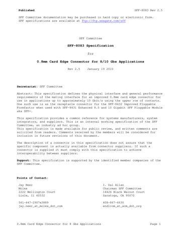
Published66.1SFF-8083 Rev 2.5Mechanical SpecificationsConnector ConfigurationsThe improved 0.8mm card edge connector relies on a receiving body and paddle card,which are the primary elements of a connector used for e.g. the SFP application.The primary elements provide a flexible means to implement solutions for diverseapplications e.g., direct board-to-board implementations can incorporate the pluginto the side of one board and mate directly to a receiving body on the other.Figure 6-1 is an example, which illustrates one style of receiving body and how theybecome receptacles to receive the plug when encapsulated by the shell that isdesigned for an unshielded connector application.FIGURE 6-1 GENERAL VIEW OF RIGHT-ANGLED BODY RECEPTACLESFF-8432 is an example of the definition of a pluggable module or cable plug thatincorporates the paddle card. It also defines the interface to a separate cage(front shell) which is used to encapsulate the receiving body to form a completereceptacle for use in shielded applications.The cage provides guidance and retention for the cable plug or pluggable module, andabsorbs the stress imposed by insertion and removal of the plug or module. Thisprotects the quality of the solder joints between the body and host board.SFF-8433 and SFF-8443 define various cage configurations that could apply to an SFP application.0.8mm Card Edge Connector for 8 Gbs ApplicationsPage 12
Published6.2SFF-8083 Rev 2.5Mechanical RequirementsThe mechanical requirements are listed in Table 6-1.TABLE 6-1 MECHANICAL REQUIREMENTSItemsConditionsDurability forConnectorDurability forMating Paddle CardEIA 364-09Mating ForceUn-mating Force6.3EIA 364-09EIA 364-13: Measurementspeed: 12.7 mm per minutemaximumEIA 364-13: Measurementspeed: 12.7 mm per minutemaximum with retentionlatch disengaged20CktAcceptance ontact SequencingTo combat electrostatic discharge, static drain, protect signal pins, or for otherpurposes, it may be desirable that during module/cable insertion some contacts makecontact first and that during extraction these contacts break last. This functioncan be achieved with contact sequencing. Figure 6-2 shows an example where first theadvanced grounding contacts make contact with the board side contacts and then thepower contacts make contact and that the signal pins make contact after ground andpower has been established. During extraction the reverse process happens. Fordetails on the sequencing dimensions see Figure 7-10.8mm Card Edge Connector for 8 Gbs ApplicationsPage 13
PublishedSFF-8083 Rev 2.5Board sidecontactsModule/Cable side contactsSignal contactsPower contactsAdvanced grounding contactsFIGURE 6-2 CONTACT SEQUENCING0.8mm Card Edge Connector for 8 Gbs ApplicationsPage 14
Published6.4SFF-8083 Rev 2.5Contact NumberingThe contact numbering is shown in Table 6-2 for the various sizes of connector. Forlocation of contacts A1 and B1, see Figure 7-1 and Figure 7-2TABLE 6-2 CONTACT NUMBERING20 Contacts1202193184175166157148139121011730 81417151650 0 645274428432942304131403239333834373536Connector DimensionsThe dimensioning conventions are described in ANSI-Y14.5M, Geometric Dimensioningand Tolerancing. All dimensions are in millimeters.Dimension related requirements for the connector system addressed in this documentare specified in the tables and figures in this clause.0.8mm Card Edge Connector for 8 Gbs ApplicationsPage 15
Published7.1SFF-8083 Rev 2.5Paddle CardFIGURE 7-1 PADDLE CARDTABLE 7-1 PADDLE ptionCL to lastCL to firstContact pad pitch within rowPad widthPaddle card widthEnd of paddle card to datum DStart of ground pad to datum DStart of power pad to datum DLength of signal padLength of component/Solder Maskkeep-out 6029.151.300.80N/A2.205.500.8mm Card Edge Connector for 8 Gbs ApplicationsToleranceBasicBasicBasic 0.05 0.15 0.10 0.05 0.05MinimumMinimumPage 16
PublishedSFF-8083 Rev 2.5A11keep-out areaPaddle card thickness1.001.001.001.00A12Paddle card end chamfer0.300.300.300.30A13Paddle card end chamfer angleLength from front edge toshoulder45 45 45 45 0.10 0.10/-0.20Reference6.006.006.006.00MinimumA140.8mm Card Edge Connector for 8 Gbs ApplicationsPage 17
Published7.2SFF-8083 Rev 2.5Board Side ConnectorFIGURE 7-2 BOARD SIDE CONNECTOR0.8mm Card Edge Connector for 8 Gbs ApplicationsPage 18
PublishedSFF-8083 Rev 2.5TABLE 7-2 BOARD SIDE 08B09B10B11B12B13B14B15B16B17DescriptionCL to lastCL to firstContact pitch within rowOverall widthOverall depthPaddle card slot widthContact tolerance zonePaddle card slot heightPaddle card slot to datum FContact pitch row to rowPeg to pegPeg heightPeg widthPeg diameterHousing to solder footOverall heightPeg CL to solder footPeg CL to card slotPeg CL to contact CLHousing Front to contact 0BasicBasicBasicMaximumMaximum 0.05MaximumMaximum 0.15BasicBasic 0.05Reference 0.05ReferenceMaximumReferenceMinimum 0.15 0.15Note: Solder footprint configuration shall conform to the footprint defined in 7.30.8mm Card Edge Connector for 8 Gbs ApplicationsPage 19
Published7.3SFF-8083 Rev 2.5Board Side Connector FootprintFIGURE 7-3 BOARD SIDE CONNECTOR FOOTPRINTTABLE 7-3 BOARD SIDE CONNECTOR 08C09C10DescriptionContact pitch within rowContact pitch row to rowPeg to pegLocator peg hole diameterPad widthPad lengthPeg hole CL to pad CLLocator peg hole CL to pad CLLocator peg hole CL to pad CLPad CL to pad CL within rowDatum H to locator peg hole CLDatum J to locator Peg Hole CLRow CL to row 500.800.800.400.4013.60 .0011.20 19.20See Note 2See Note 28.208.200.8mm Card Edge Connector for 8 Gbs 101.401.0027.20BasicBasicBasic 0.05 0.03 0Page 20
InfiniBand Architecture Specification Volume 2 T10/1601D SAS 1-1 (Serial Attached SCSI - 1.1) INF-8074i SFP (Small Formfactor Pluggable) Transceiver SFF-8075 PCI Card Version of SFP Cage SFF-8084 0.8mm Card Edge Connector SFF-8410 High Speed Serial Testing for Copper Links