Transcription
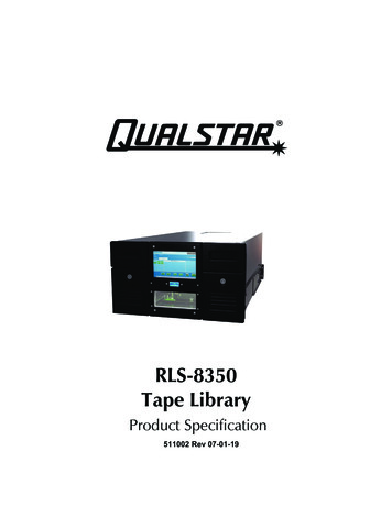
RLS-8350Tape LibraryProduct Specification511002 Rev 07-01-19
Copyright NoticeCopyright 2016 by Qualstar Corporation — All Rights ReservedInformation contained in this document is copyrighted by Qualstar Corporation. It isintended for use by Qualstar's customers and prospective customers to evaluate,integrate, operate and maintain Qualstar products. Customers and prospectivecustomers may reproduce this document as needed for these uses. Reproduction inwhole or in part for any other use or by any other party is prohibited without priorwritten permission from Qualstar Corporation.Every effort has been made to keep the information contained in this documentcurrent and accurate as of the date of publication or revision. However, no guaranteeis given or implied that the document is error-free or that it is accurate with regard toany specification.Qualstar reserves the right to modify the design or specification without notice. Thisspecification may not be construed as a contractual obligation except as specificallyagreed to by Qualstar in writing at the time of order.Qualstar and the Qualstar logo are registered trademarks of Qualstar Corporation.Other trademarks are the property of their respective owners.NoticesQualstar products may be covered by one or more of the following U.S. patents:6,163,139 and 6,560,061. Other patents pending.Qualstar equipment is manufactured from new parts, or new and used parts. In somecases, Qualstar equipment may not be new and may have been previously installed.Regardless, Qualstar’s warranty terms apply unless the equipment is specificallyidentified by Qualstar as “used” or “refurbished”.This equipment has been tested and found to comply with the limits for a Class Adigital device, pursuant to Part 15 of the FCC Rules. These limits are designed toprovide reasonable protection against harmful interference when the equipment isoperated in a commercial environment. This equipment generates, uses, and canradiate radio frequency energy and, if not installed and used in accordance with theinstruction manual, may cause harmful interference to radio communications.Operation of this equipment in a residential area is likely to cause harmfulinterference in which case the user will be required to correct the interference at hisown expense. Shielded cables are required for this device to comply with FCC Rules.Use shielded cables when connecting this device to others.511002 Rev 07-01-19i
For information about this product specification, please visit our website or callQualstar at:QUALSTAR CORPORATION1267 Flynn RoadCamarillo, CA 93012FAX: (805) 978-5984Phone: (805) 583-7744E-Mail: sales@qualstar.comwww.qualstar.comii511002 Rev 07-01-19
Table of Contents1.2.Introduction . 1-11.1Scope . 1-11.2Supplemental Documentation . 1-1Product Description . 2-12.1General Description . 2-12.2Standard Features Found in the RLS-8350 Library . 2-12.3Optional Features Available . 2-22.4RLS-8350 Library Features and Options . 2-32.5Major Features. 2-42.5.1Cabinet . 2-42.5.2Front Panel Components . 2-42.5.3Rear Panel Components . 2-62.5.4Medium Changer Components . 2-92.63.4.2.6.1Medium Changer Control System . 2-112.6.2Inventory Database . 2-112.6.3Library and Multi-Sequential (Multiple Stacker) Operation . 2-122.6.4Manual Operation . 2-122.6.5Library Partitions. 2-132.6.6Encryption Key Management . 2-13Physical Specifications. 3-13.1Dimensions . 3-13.2Color . 3-13.3Weights . 3-2Electrical Specifications . 4-14.15.RLS Operation . 2-11Standard AC Power Requirements and Consumption . 4-14.1.1Power Source Disturbances . 4-24.1.2Power Entry . 4-24.1.3Power Cord. 4-2Agency Compliance . 5-15.1EEC Directive Compliance (European Economic Community) . 5-15.2Emissions/Immunity Standards Compliance . 5-15.3Safety Standards Compliance . 5-15.4European Directive on Waste Electrical and Electronic Equipment (WEEE) . 5-15.4.15.56.End of Life Instructions . 5-2Reduction of Hazardous Substances (RoHS) . 5-2Performance Specifications. 6-1511002 Rev 07-01-19iii
7.8.iv6.1Data Cartridge Handling Times . 6-16.2Scan All Barcodes . 6-1Environmental Specifications . 7-17.1Temperature, Humidity and Altitude . 7-17.2Acoustical Noise . 7-1Maintainability . 8-18.1Mean Time to Repair . 8-18.2Preventive Maintenance . 8-18.3Automated Tape Drive Cleaning . 8-18.4Adjustments . 8-1511002 Rev 07-01-19
1.Introduction1.1 ScopeThis product specification describes the Qualstar RLS-8350 tape library, subsequentlyreferred to in this specification as the RLS or library. It also provides detailedspecifications of the product and is intended for use by individuals evaluating,purchasing and/or integrating the RLS library products.1.2 Supplemental DocumentationFor information about the data interface, or other information outside the scope ofthis manual, please refer to the appropriate documents listed below. The followingQualstar and ANSI documents supplement this rInstallation & OperationRLS-8350/85XXX SeriesInstallation and Operation Manual511000ServiceRLS-8350/85XXX SeriesTechnical Service Manual511010Approved Data CartridgesProduct Information NotePIN-038Barcode Label SpecificationsProduct Information NotePIN-040SCSI Command InformationRLS SCSI-2 Interface Manual501551SCSI-1ANSI X3.131-1986N/ASCSI-2ANSI X3.131-1994N/ASCSI Parallel Interface-2 Specification (SPI-2)ANSI X3.302-1998N/ASCSI Architecture Model-2 (SAM-2)ANSI INCITS 366-2003N/ASCSI-3 Primary Commands (SPC)ANSI X3.301-1997N/ASCSI-3 Primary Commands - 2 (SPC-2)ANSI INCITS 351-2001N/ASCSI-3 Primary Commands - 3 (SPC-3)ANSI INCITS 408-2005N/ASCSI-3 Media Changer Commands (SMC)ANSI INCITS 314-1998 [R2003]N/AAutomation/Drive Interface - Transport Protocol (ADI)ANSI INCITS 406-2005N/AAutomation/Drive Interface - Commands (ADI)ANSI INCITS 403-2005N/ASerial Attached SCSI - 1.1 (SAS-1.1)ANSI INCITS 417-2006N/ATable 1-1 Applicable Documents511002 Rev 07-01-19Introduction1-1
2.Product Description2.1 General DescriptionThe RLS-8350 is a high density, automated rack mounted tape library. The library is6 rack-units tall (6U 10.50 inches). The RLS-8350 tape library utilizes LTO tapetechnology.The library supports up to 50 cartridges and four tape drives. The entire system(drives and library) is under host control via the host interface. Fibre channel andSAS tape drive interfaces are supported, and the library uses the ADI facility of thetape drives for its interface.The RLS-8350 library can be easily expanded by adding one to three RLS-8560 orRLS-85120 libraries, housing up to 410 tape cartridges and up to 19 tape drives injust 36U of rack space.The library contains a robotics system for handling data cartridges, up to fourLTO-6, LTO-7 or LTO-8 SAS or fibre channel tape drives and storage slots for datacartridges. The unit operates on internationally available AC power with activepower factor correction.The RLS is designed for maximum reliability. Only the highest quality componentsare used in a design that is inherently robust and simple. Brushless motors are usedexclusively for smooth and reliable operations. All digital, closed-loop servo systemsuse magnetic and optical position sensors to assure fast, smooth, trouble-freecartridge handling. The servos automatically calibrate themselves, eliminating allelectrical adjustments. Preventive maintenance consists of replacing the air filter andcleaning the gripper pads, when prompted by the control panel.2.2 Standard Features Found in the RLS-8350 Library Library interface to the application is established via ADI, (Automation/Drive Interface)through the tape drive's interface Barcode scanning of data cartridge labels Q-Link web-based library manager can remotely control the RLS and automaticallyemail alarm messages to a contact list Supports Internet Protocol Version 6 (IPv6) Supports library managed encryption, which allows tape drives to encrypt the datawritten on tape cartridges Rack mount kit Simultaneous random and multi-sequential operating modes with two or more tapedrives Library resources may be partitioned511002 Rev 07-01-19Product Description2-1
Multiple initiators may simultaneously connect to a single partition The front panel has a window for visibility into the interior Interior illumination Color touch screen control panel Easy-to-use menu system for configuration, operation and maintenance Tape drives are in quick-change hot swappable carriers Programmable, automated tape drive cleaning Operating firmware may be updated via Q-Link Ethernet interface Maintenance-friendly by design: no adjustments, hot-swap drives, hot-swap powersupply modules. All service can be performed without removing from the rack. Filtered, forced-air cooling of library and tape drives provided by front replaceable airfilters Universal input power rating (100- to 240-VAC, 50/60 Hz) Power Factor Corrected (PFC) power system is efficient and fully CE compliant2.3 Optional Features Available N 1, hot-swappable power supply modules (automatic e-mail alarm message sent via QLink when any power supply or fan fails) FastPass elevator expansion option, which allows one to four RLS-8560 or RLS-85120libraries to be connected to form a single library.2-2Product Description511002 Rev 07-01-19
2.4 RLS-8350 Library Features and OptionsFEATURETape TechnologyRLS-8350LTOMaximum Number of Drives4Number of Slots50I/O Ports1Cartridges per I/O Port4Barcode ReaderStandardQ-Link Remote Library ManagerStandardHot-swap Tape Drive CarriersStandardN 1, Hot-Swappable Power SupplyModulesOptionalTable 2-1 RLS-8350 Features and Options511002 Rev 07-01-19Product Description2-3
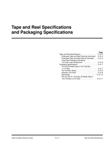
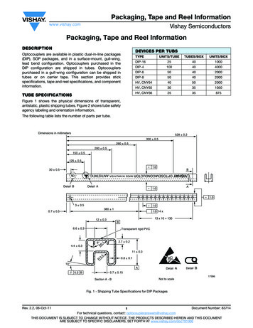
2.5 Major Features2.5.1 CabinetThe cabinet provides easy access for upgrades and field service while the library isinstalled in a standard 19” equipment rack. Tape drives and power supply modules(PSMs) plug into the rear of the library, providing all power and data connections.2.5.2 Front Panel ComponentsThe library’s functions can be controlled through the control panel. The I/O port isreleased by the robot and slides out from the front panel, and is electronically locked.Bulk loading can be accomplished by removing the right or left storage matrix. Figure2-1 shows the various features of the front panel. The library may be configured tocontinue operation while the I/O port is extended.Figure 2-1 RLS-8350 Front Panel Details2-4Product Description511002 Rev 07-01-19
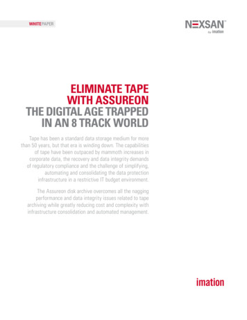
2.5.2.1 Control PanelThe control panel is a color LCD with touch screen. The operator may use the controlpanel menus to configure and operate the RLS and monitor its status. The followinginformation can be displayed: Model number and all firmware revisions Extensive menu system for configuration, maintenance and operation Operational status (indicates all active cartridge movements) History log which stores the most recent commands and status Error conditions and diagnostic messages Library partition information Inventory information2.5.2.2 I/O PortThe operator gains access to the media by unlocking the I/O port through either thecontrol panel or Q-Link and then manually extending the I/O port. When closed, theI/O port is locked electronically. Once extended, four cartridges may be removed orinserted. The library status may be configured to be "not ready" when the I/O port isextended. Under this configuration, while the port is open, the RLS can respond to ahost interface command with a busy status, a not ready status or it can accept thecommand and wait for port closure to complete the command.Figure 2-2 The Four Slot I/O Port Extended511002 Rev 07-01-19Product Description2-5
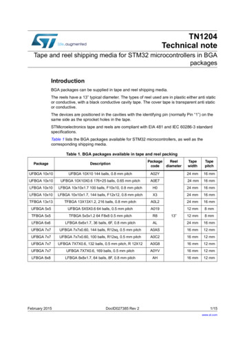
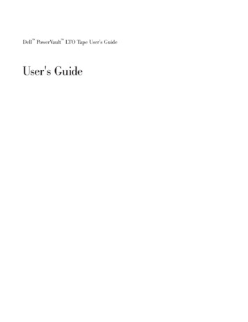
2.5.2.3 SecurityThe storage matrix must be secured with a key operated lock for the library tooperate.2.5.2.4 Power Switch and IndicatorThe library’s power status is indicated by a blue LED Power Indicator button on thefront of the library that illuminates when the power is applied. Standby/Soft-power iscontrolled by a switch located inside the LED Power Indicator button. During standbymode the center of the button flashes blue at the rate of one blink approximatelyevery two seconds. During power on mode the button is fully illuminated.The primary power for the library is controlled by a rocker switch located on the rearpanel.2.5.3 Rear Panel ComponentsTape DrivesControlElectronicsPowerSupplyModulePower Inlet, Line Fuse and Rocker SwitchFigure 2-3 Rear Panel Details2.5.3.1 N 1 Power OptionThe RLS-8350 has a distributed power system. One or two power supply modules(PSM) can be accommodated. One power supply module is standard, the second powersupply module provides N 1 capability, ensuring system redundancy.The PSMs operate in parallel, sharing the load. This reduces the stress on theindividual power supplies and extends their service life. When the N 1 option is2-6Product Description511002 Rev 07-01-19
installed, the library will continue to operate if one module fails. The remaining PSMwill power the RLS-8350 indefinitely. The library and tape drives will continue tofunction, uninterrupted by the failure and subsequent replacement of the failed PSM.A green "power good" LED indicates that a PSM is operating properly. A failed PSMcauses an alarm condition that will result in e-mail notification by the Q-Link remotelibrary manager.All PSMs supply regulated 24-volts DC to the RLS-8350. The unit is powered from ACmains of 100- to 240-volts, 50 or 60 Hertz.Figure 2-4 The Power Supply Module (PSM)2.5.3.1 FastPass Elevator Expansion OptionRLS-8350 rack mounted tape libraries easily expand capacity and data deliveryperformance to keep pace with rapidly growing data protection and data archivingrequirements. Each library can be equipped to pass tapes vertically from one unit tothe next when installed in an industry standard 19-inch EIA equipment rack.The FastPass elevator expansion option passes tapes from unit to unit. Themechanism installs from the rear of the rack and fits entirely within the form factor ofthe libraries.The FastPass option can be installed by an end user, and the system is completelyself-calibrating. The elevator option requires no additional power or cooling, and doesnot reduce the number of tape drives housed in each library module. The fast passmodules use a tape drive slot, reducing the possible number of tape drives by two foreach pair of libraries that are connected.Each RLS-8350 library can be expanded by adding one to three RLS-8560 or RLS85120 libraries below it, enabling the total configuration to support up to 19 tapedrives and up to 410 tape cartridges.511002 Rev 07-01-19Product Description2-7
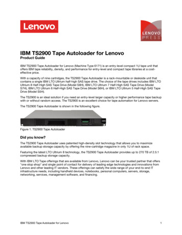
Figure 2-5 Two Libraries Connected with the FastPass Elevator Expansion OptionUpper elevatorexpansionmoduleLower elevatorexpansionmoduleFigure 2-6 Rear view of two libraries with the FastPass Elevator Expansion Option2-8Product Description511002 Rev 07-01-19
2.5.4 Medium Changer ComponentsRoboticsI/O PortTape DrivesStorage SlotsFigure 2-7 RLS Components2.5.4.1 Storage SlotsEach RLS-8350 model utilizes a left and right fixed matrix of storage slots (28 slots onthe right side and 22 on the left). The storage matrices may be removed from the unitfor bulk loading or removal of cartridges.Figure 2-8 Left Storage Matrix Extended511002 Rev 07-01-19Product Description2-9
2.5.4.2 Tape DrivesThe RLS-8350 library accommodates up to four tape drives. The drives are housed inplug-in drive carriers that may be installed or removed while the other drives withinthe unit are operating. A microprocessor in the drive carrier communicates with thetape drive via its supervisory port to ascertain its model, serial number andoperational status. This information is immediately uploaded to the executiveprocessor and is available to the host computer whenever a new drive is plugged-in.The drive’s world-wide name is set to the RLS menu values as soon as power isapplied. Any tape drive may be inserted or removed while the others are running. Adrive can be changed within a minute and no tools are required. Blank filler panelsmust be installed at each vacant tape drive location.Figure 2-9 Tape Drive Assembly2.5.4.3 RoboticsThe RLS-8350 utilizes a four-axis robotic cartridge handling system that movescartridges between the storage slots and the tape drives. All axes are driven by vectordrive brushless DC motors. The motors move the linear axes with precision leadscrews. Feedback is provided by hall effect sensors with optical end-of-travel sensing.Cartridge gripping is accomplished using a solenoid for simplicity and dependability.The linear axes are riding on linear bearings, and the rotating axis is supported onball bearings. This results in high reliability, long life, and nearly zero maintenancefor the robotics. The entire robotic handler is a removable as a single unit through thefront with only 7 screws, without removing the library from the equipment rack.Figure 2-10 The Robotics2-10Product Description511002 Rev 07-01-19
2.5.4.4 Cooling SystemThe library is cooled by fresh air that is drawn into the cabinet through filters in thefront panel. The air is exhausted out the rear of the library. Each tape drive andpower supply module has a fan.2.5.4.5 Barcode ReaderA barcode reader is included with all RLS models. The barcode reader can scan allcartridges in the RLS (except those within tape drives), as well as cartridgesintroduced into the I/O port. Barcode LabelsPre-printed barcode labels, which are both human and machine-readable, areavailable from a number of sources, including Qualstar.Barcode labels must conform to ANSI/AIM BCI-1995, Uniform SymbologySpecification Code 39. Please refer to PIN-040 at www.qualstar.com for moreinformation.By default, the RLS expects no modulus 43 check characters at the end of each label,but can be configured to expect the check character. All of the labels within the RLSmust match the check character configuration. If the RLS is configured to expect acheck character and the labels do not have a check character, then most barcodes willnot read, and if they do read, then they will miss the last character. If the RLS isconfigured for no check character, and labels with check characters are used, then allof the labels will show an extra character.2.6 RLS Operation2.6.1 Medium Changer Control SystemThere are several microprocessors utilized throughout the RLS to form an efficientdistributed control system. All of the microprocessors utilize FLASH memory forstoring their operating firmware. In addition to its own needs, the executive processorfirmware contains the firmware images for all of the other microprocessors in theRLS. Thus all of the RLS operating firmware gets updated with a single code load tothe executive processor. The code load is accomplished over the Ethernet interfaceusing an Internet browser. The updates are matched to the revisions of all the circuitboards to insure compatibility. Power loss during uploading or re-programming willnot cause any harm.2.6.2 Inventory DatabaseThe medium changer maintains an Inventory Database that contains data associatedwith each storage location. The database contains such information as cartridgepresence, barcode label data and cartridge source element address. In addition, thelibrary collects the Memory-In-Cartridge data from each tape cartridge that isinserted into a tape drive. This information is available using the Control Panel or theQ-Link remote management facility. A subset of this is available to the host using theSCSI command set.511002 Rev 07-01-19Product Description2-11
2.6.3 Library and Multi-Sequential (Multiple Stacker) OperationEach tape drive and cartridge storage location in the RLS may be configured throughthe menu system for Library or Sequential operation. If a tape drive is configured forthe Library mode, it becomes a resource controlled by the application operating thelibrary. If a drive is configured for Sequential mode operation, it is referred to as asequential drive and is not included in the list of resources reported.For Sequential or Recycle operation, a set of cartridge locations is assigned to eachsequential drive for its exclusive use. In these modes, each tape cartridge is returnedto its original storage location after it is ejected from the tape drive.For Dual Bin operation, two separate sets of cartridge locations are assigned to eachsequential drive for its exclusive use. The input set of locations is where the changergets cartridges to be placed in the sequential drive. The output set is where thosecartridges are returned after the drive has ejected them.Cartridge storage locations assigned to sequential operations are not included in thelist of resources reported to host computers. Empty slots in a Sequential, Recycle orDual Bin drive’s storage location set will not adversely affect operation.When a Sequential or Recycle operation is initiated the changer places the firstcartridge, found at (or after) the initial specified storage location into the drive. Whenthe drive ejects the cartridge, the changer automatically returns the cartridge to itsoriginal location. The changer then places the next cartridge found in sequence withinthe drive’s storage set into the drive. This process is repeated until the last specifiedcartridge in the sequence is ejected and returned to storage. This sequence may beinitiated at any location within a Sequential drive’s storage set but will always end atthe last storage location in the sequence. In Recycle operations, the handler willreturn to the starting position and repeat the cartridge movement cycle indefinitely.When a Dual Bin operation is interactively started, the changer moves the cartridgefound at (or after) its first input set location into the drive. When the drive ejects thecartridge, the changer automatically places it in the first empty cartridge location inthe drive’s output set. This process is repeated, until the last specified cartridge in theinput set has been ejected from the drive and placed into the output set.The computer communicating with the sequential drive only communicates with thedrive and not the changer. This allows the use of applications lacking library-specific,cartridge-movement, operating software.Multiple tape drives can be configured for concurrent Sequential, Recycle or Dual Binoperation. All Library drives, and all cartridge locations not assigned to sequentialdrives, are still available for simultaneous random mode operations.This flexible design allows the user to partition the library’s resources to best meetoverall system needs.2.6.4 Manual OperationThe menu system provides a means of manually moving cartridges to or from allavailable locations (drives, magazine slots and I/O port). The menu system is accessed2-12Product Description511002 Rev 07-01-19
using the touch screen on the front panel, or via the Q-Link interface. If the host makesa request to the RLS during a manual operation, the RLS indicates it is busy until themanual operation is completed (usually within a few seconds).2.6.5 Library PartitionsWhen shipped from the factory, all RLS units are configured as a single library with alltape drives and storage slots dedicated to random operation. This is generally the correctconfiguration for a single system running a library-aware backup application.However, when multiple hosts are present and each needs to run a library specificbackup application, then the RLS can be sub-divided into smaller library partitions.Each partition requires at least one dedicated tape drive. Note that when tape drivesare dedicated to sequential operation (sequential, recycle or dual bin) only one tapedrive is allowed to be assigned to each library partition.The RLS can have multiple physical partitions, which allows separate hosts and thusseparate host applications to have fully separate sub-libraries under their exclusivecontrol. A partition must have one or more drive slots, and one or more cartridge slotsassigned. Thus, the maximum number of partitions is a function of the resourcesassigned to the various partitions, up to the total number of drive slots and thenumber of cartridge slots in the Library. Note that a drive slot can be assigned but isnot active unless a drive is installed. Drives, drive slots, and cartridge slots cannot beshared between partitions.An individual I/O port slot can only be assigned to one partition. A unit with two (2)I/O ports doubles the number of I/O port slots that can be assigned to partitions. Aswith drives, drive slots, and cartridge slots, I/O port slots that are assigned to onepartition may not be shared with a different partition.Multiple hosts can communicate with the same partition, via the same physical portand LUN. Should a host need a separate physical connection to the partition, anadditional drive can be configured for each physical host interface needed.2.6.6 Encryption Key ManagementThe RLS-8350 Series enables use of the powerful data encryption capability built intoevery LTO tape drive. Simple, easy-to-use, library-based key management allowsAdministrators to assign a separate key to each partition. The data on all tapes within apartition are encrypted and decrypted with the user-supplied key.511002 Rev 07-01-19Product Description2-13
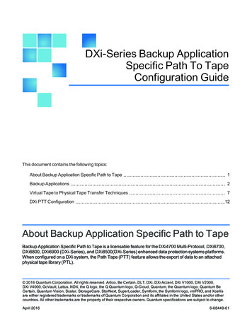
3.Physical Specifications3.1 DimensionsFigure 3-1 RLS External DimensionsNote: 12 additional inches (30.5 cm) of depth are required to remove and install tapedrives and power supplies.3.2 ColorThe exterior color is black/aluminum.511002 Rev 07-01-19Physical Specifications3-1
3.3 WeightsMODELRLS-8350WEIGHTFULLY LOADED (LBS / KG)EMPTYWEIGHT (LBS / KG)138 LBS / 63 KG50 LBS / 23 KG Includes rack mount kit and a full complement of tape drives and tape cartridges Not including magazines, tape cartridges or drivesTable 3-1 R
This product specification describes the Qualstar RLS-8350 tape library, subsequently referred to in this specification as the RLS or library. It also provides detailed . Serial Attached SCSI - 1.1 (SAS-1.1) ANSI INCITS 417-2006 ; N/A . Table 1-1 Applicable Documents. 511002 . Rev 07-01-19. Introduction 1-1 . 2. Product Description